Asus Z10PE-D8 WS Manual de Usario
Asus
Placa madre
Z10PE-D8 WS
Lee a continuación 📖 el manual en español para Asus Z10PE-D8 WS (202 páginas) en la categoría Placa madre. Esta guía fue útil para 5 personas y fue valorada con 4.5 estrellas en promedio por 2 usuarios
Página 1/202

Z10PE-D8 WS

Copyright © 2019 ASUSTeK COMPUTER INC. All Rights Reserved.
Contents
Notices viii .....................................................................................................................
Safety information x .......................................................................................................
About this guide xi .........................................................................................................
Z10PE-D8 WS specifications summary xiii ..................................................................
Chapter 1: Product Introduction
1.1 Welcome! .................................................................................................... 1-2
1.2 Package contents 1-2 ......................................................................................
1.3 Serial number label 1-3 ....................................................................................
1.4 Special features.......................................................................................... 1-3
Chapter 2: Hardware Information
2.1 Before you proceed 2-2 ...................................................................................
2.2 Motherboard overview 2-3 ...............................................................................
2.3 Central Processing Unit (CPU) 2-7 .................................................................
2.4 System memory 2-12 .......................................................................................
2.5 Expansion slots 2-15 ........................................................................................
Contents
2.6 Onboard buttons and switches 2-18 ..............................................................
2.7 Onboard LEDs 2-20 ..........................................................................................
2.8 Jumpers .................................................................................................... 2-28
2.9 Connectors ............................................................................................... 2-33
Chapter 3: Powering Up
3.1 Starting up for the first time 3-2 ......................................................................
3.2 Powering off the computer 3-3 ........................................................................
Chapter 4: BIOS Setup
4.1 Managing and updating your BIOS 4-2 ..........................................................
4.2 BIOS setup program 4-6 ..................................................................................
4.3 Main menu 4-9 ..................................................................................................
4.4 AiTweaker menu 4-10 .......................................................................................

Contents
4.5 Advanced menu 4-13 .......................................................................................
4.6 IntelRCSetup menu 4-29 ..................................................................................
4.7 Server Mgmt menu 4-45 ...................................................................................
4.8 Event Logs menu 4-49 .....................................................................................
4.9 Monitor menu 4-51 ...........................................................................................
4.10 Security menu 4-52 ..........................................................................................
4.11 Boot menu 4-55 ................................................................................................
4.12 Tool menu 4-56 .................................................................................................
4.13 Exit menu 4-57 ..................................................................................................

Chapter 5: RAID Configuration
5.1 Setting up RAID 5-2 ..........................................................................................
5.2 LSI Software RAID Configuration Utility 5-4 .................................................
5.3 Intel® Rapid Storage Technology enterprise
SATA/SSATA Option ROM Utility 5-24 ...........................................................
5.4 Intel® Rapid Storage Technology enterprise (Windows) 5-32 ......................
Contents

Contents
Chapter 6: Driver Installation
6.1 RAID driver installation 6-2 .............................................................................
6.2 Software drivers and utilities installation 6-13 ..............................................
6.3 Running the Support DVD 6-13 .......................................................................
6.4 Installing the drivers and utilities 6-16 ..........................................................
6.5 Running the utilities 6-20 .................................................................................
Appendix A: Reference Information
A.1 Z10PE-D8 WS block diagram A-2 ...................................................................
A.2 Audio I/O connections A-3 ..............................................................................
ASUS contact information 1 ..........................................................................................

REACH
Compliance Statement of Innovation, Science and Economic
Development Canada (ISED)
Déclaration de conformité de Innovation, Sciences et
Développement économique Canada (ISED)

Safety information
Electrical safety
Operation safety
DO NOT
DO NOT

About this guide
How this guide is organized
• Chapter1:ProductIntroduction
• Chapter2:HardwareInformation
• Chapter3:PoweringUp
• Chapter4:BIOSSetup
• Chapter5:RAIDConfiguration
• Chapter6:DriverInstallation
• Appendix:ReferenceInformation
Where to find more information
1. ASUS websites
2. Optional documentation

Conventions used in this guide
Typography
Bold text
Italics
Command
format A:/S
DANGER/WARNING:
CAUTION:
IMPORTANT:
NOTE:

Z10PE-D8 WS specifications summary
CPU
* Refer to www.asus.com for CPU support list
Chipset
Memory
* Actual memory frequency differs from Intel CPU types and memory
modules. 2400MT/s is supported only with E5-2600 v4 CPUs.
** Refer to www.asus.com for the memory QVL (Qualified Vendors Lists).
Expansion slots
* This motherboard is ready to support PCIe 3.0 specification. Functions will
be available when using PCIe 3.0-compliant devices. Refer to
www.asus.com for the latest updates and information.
VGA Output
Multi-GPU support
Storage
Intel® C612 with Intel RSTe:
ASMedia®
SATA Express controller***:
* M.2 Socket 3 supports M Key and type 2260/2280/22110 storage devices.
** LSI MegaRAID only support SATA Controller
*** These functions will work depending on the CPU installed.

Z10PE-D8 WS specifications summary
LAN
Audio
USB
ASMedia USB 3.0 controllers
Intel®C612 Chipset
Key Selling Points
Workstation Unique
Features

1.1 Welcome!
1.2 Package contents
Standard Gift Box
Pack Standard Bulk Pack
Cables
VGA cable with bracket
SATA 6G cable
COM port cable
I/O Modules 2-port USB 2.0
Accessories
IO shield
2-Way SLI Bridge
connector
3-Way SLI Bridge
connector
4-Wat SLI Bridge
connector
ASWM Enterprise SDVD
Application CD Support CD
Packing Qty.
Optional items Description

1.4 Special features
1.4.1 Product highlights
Latest Processor Technology
Intel AVX 2.0
Next Generation of processor power management
DDR4 memory support
1.3 Serial number label
xxS1xxxxxxxx
xxS1xxxxxxxx
Z10PE-D8 WS Made
in
Taiwan
合格
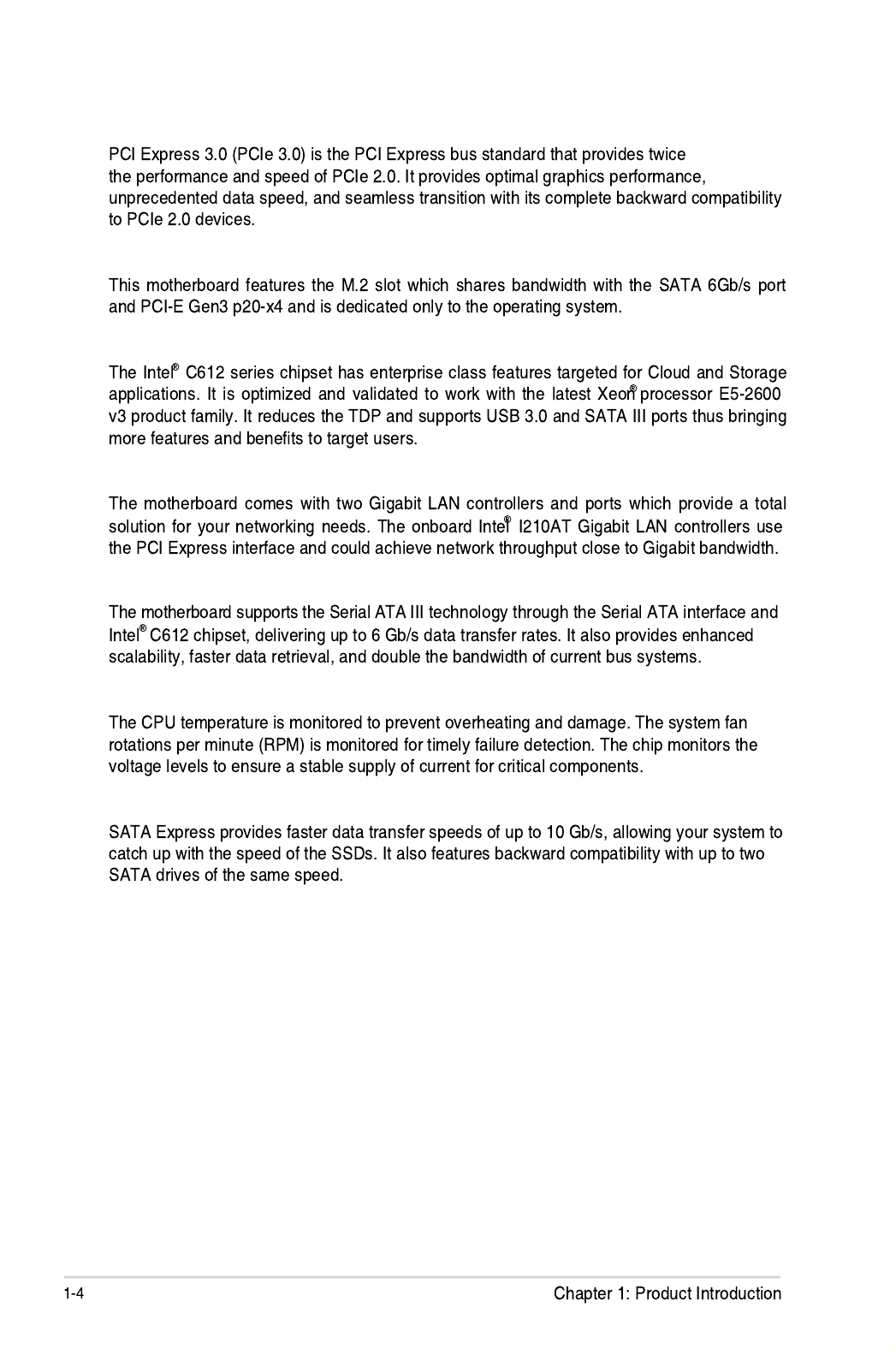
PCI Express 3.0
M.2 Support
Intel® C612 Series Chipset
Intel® I210AT LAN Solution
Serial ATA III technology
Temperature, fan, and voltage monitoring
SATA Express support

1.4.2 Innovative ASUS features
ASUS Fan Speed control technology
Best graphics performance for 4-way NVIDIA® GeForce® SLI™
Q-Code Logger
ProCool Connector
ASUS Dr. Power
Ai Charger+
USB Charger+


Hardware Information
Chapter 2: Hardware Information

2.1 Before you proceed

2.2 Motherboard overview
2.2.1 Placement direction
2.2.2 Screw holes
Place this side towards
the rear of the chassis

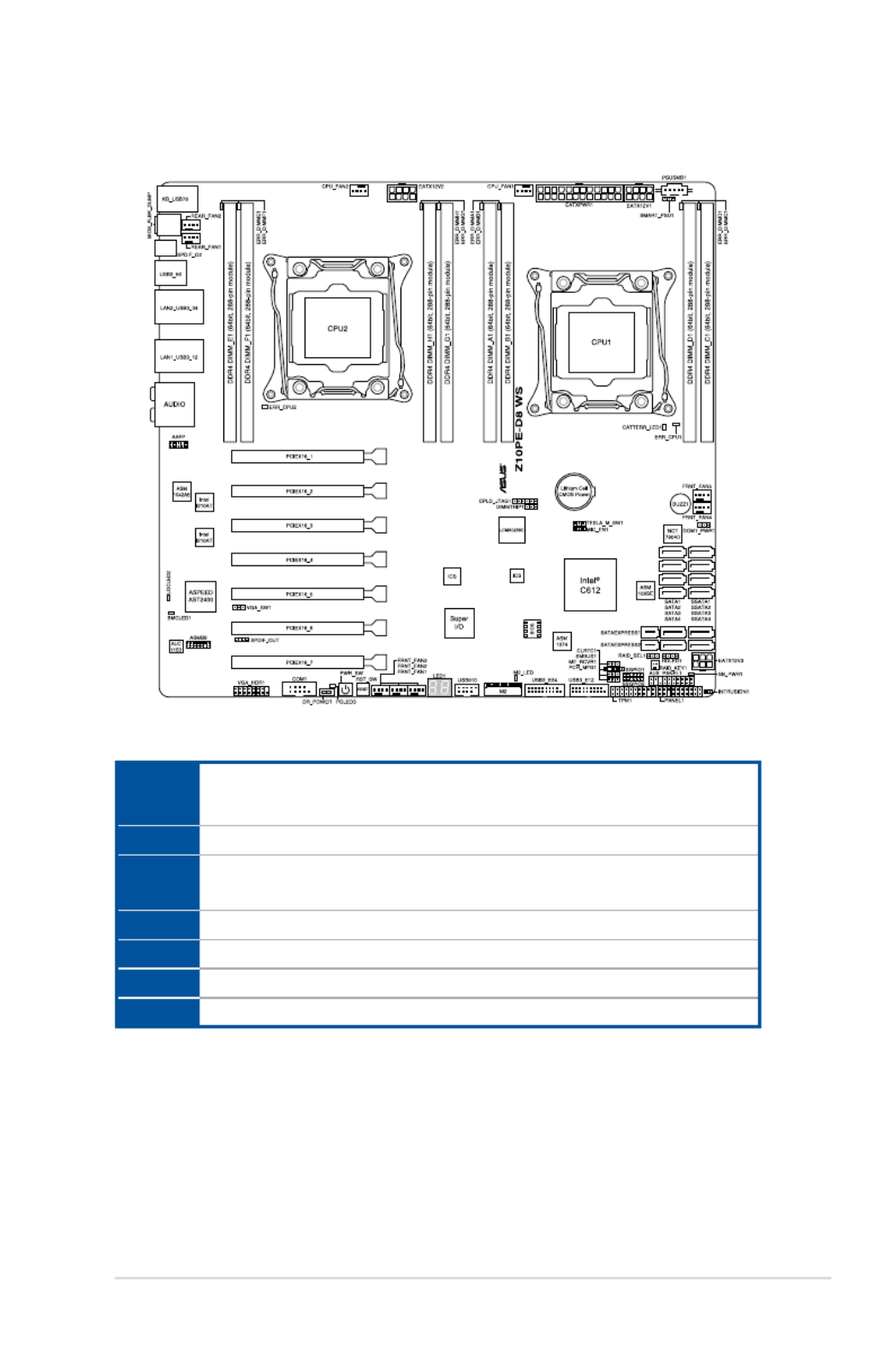
2.2.3 Z10PE-D8 WS Motherboard layout

2.2.4 Layout contents
Jumpers Page
Slots/Socket Page
Onboard buttons and switches Page
Onboard LEDs Page

Rear panel connectors Page
Internal connectors Page

2.3.1 Installing the CPU
2.3 Central Processing Unit (CPU)
Triangle mark

Load lever

2-10 Chapter 2: Hardware Information
10. Pushdowntherightloadlever(I)ensuringthattheedgeoftheloadplateisxedand
tuckedsecurelyunderthelever(J)theninsert the right load lever under the retention
tab(K).
The PnP cap pops out of the load plate when the right load lever is inserted into the
retention tab.
KeepthePnPcap.ASUSwillprocessReturnMerchandiseAuthorization(RMA)requests
onlyifthemotherboardcomeswiththePnPcapontheLGA2011socket.
11. Pushdowntheleftloadlever(L)then
insertitundertheretentiontab(M). Retention tab
PnP cap
ASUS Z10PE-D8 WS 2-11
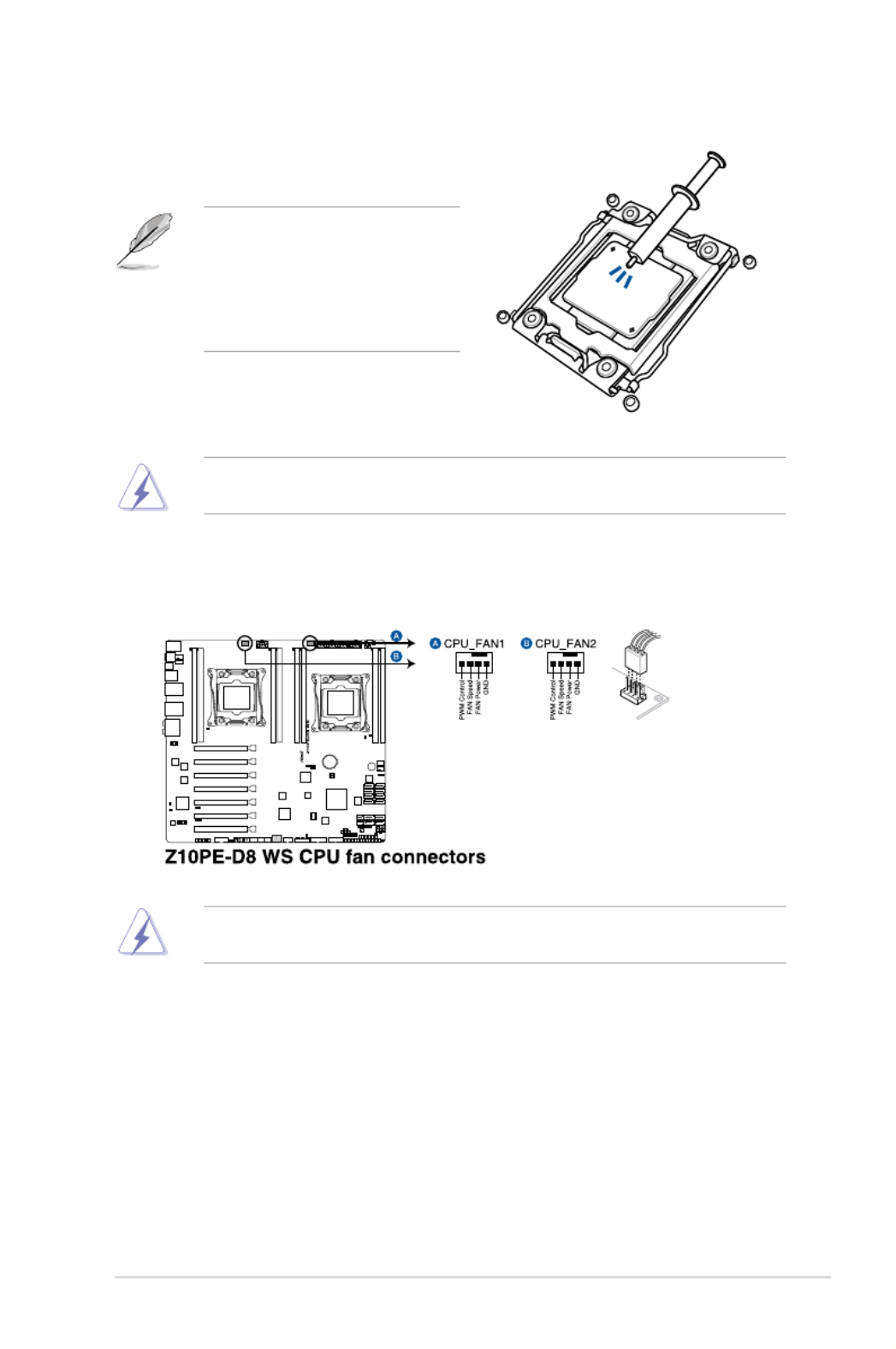
13. ConnecttheCPUfancabletotheconnectoronthemotherboardlabeledCPU_FAN1/
CPU_FAN2.
DONOTforgettoconnecttheCPUfanconnector!Hardwaremonitoringerrorscanoccurif
you fail to plug this connector.
TheThermalInterfaceMaterialistoxicandinedible.DONOTeatit.Ifitgetsintoyoureyes
ortouchesyourskin,washitoffimmediately,andseekprofessionalmedicalhelp.
• EnsurethattheThermalInterface
Materialisspreadinaneventhin
layer.
• Someheatsinkscomewithpre-
appliedThermalInterfaceMaterial.
Ifso,skipthisstep.
12. ApplysomeThermalInterfaceMaterial
totheexposedareaoftheCPUthatthe
heatsink will be in contact with.
2-12 Chapter 2: Hardware Information
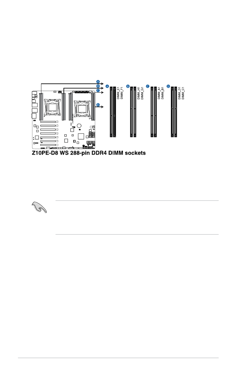
2.4 System memory
2.4.1 Overview
Themotherboardcomeswitheight(8)DoubleDataRate4(DDR4)DualInlineMemory
Modules(DIMM)sockets.
ThegureillustratesthelocationoftheDDR4DIMMsockets:
2.4.2 Memory Configurations
Youmayinstall4GB,8GB,16GB,and32GBRDIMMsor32GBand64GBLR-DIMMsinto
theDIMMsocketsusingthememorycongurationsinthissection.
• RefertoASUSServerAVLfortheupdatedlistofcompatibleDIMMs.
• WheninstallingDIMMs,alwaysstartfromslotA1(CPU1)andE1(CPU2).
• AlwaysinstallDIMMswiththesameCASlatency.Foroptimumcompatibility,itis
recommended that you obtain memory modules from the same vendor.
ASUS Z10PE-D8 WS 2-13
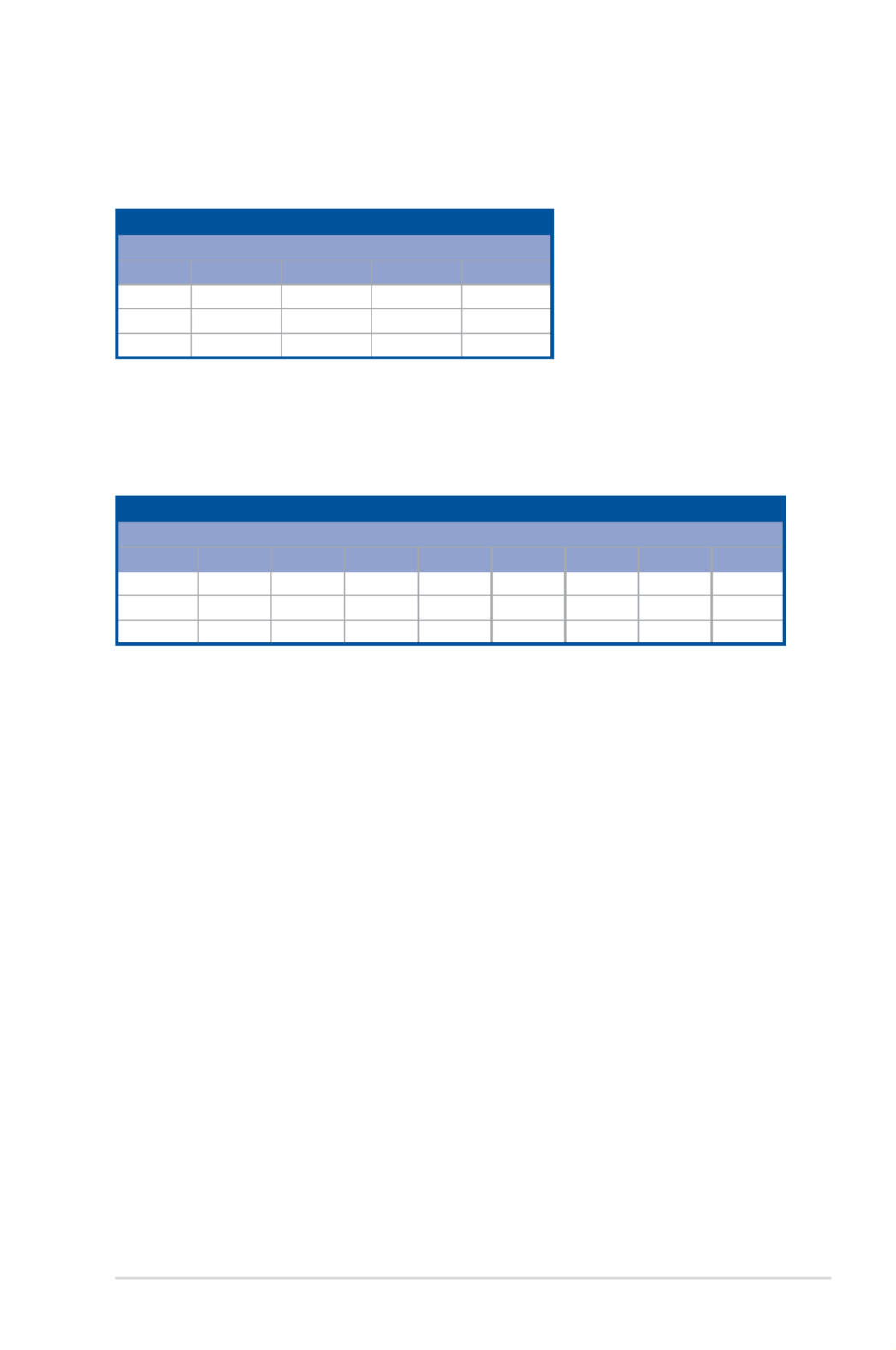
Single CPU configuration (must be installed on CPU1)
DIMM
A1 B1 C1 D1
1 DIMM P
2 DIMMs P P
4 DIMMs P P P P
Dual CPU configuration
YoucanrefertothefollowingrecommendedmemorypopulationforadualCPUconguration.
Single CPU configuration
YoucanrefertothefollowingrecommendedmemorypopulationforasingleCPU
conguration.
Dual CPU configuration
DIMM
A1 B1 C1 D1 E1 F1 G1 H1
2 DIMMs P P
4 DIMMs P P P P
8 DIMMs PPPPPPPP

ASUS Z10PE-D8 WS 2-15
2.5 Expansion slots
Inthefuture,youmayneedtoinstallexpansioncards.Thefollowingsubsectionsdescribethe
slots and the expansion cards that they support.
2.5.1 Installing an expansion card
Toinstallanexpansioncard:
1. Beforeinstallingtheexpansioncard,readthedocumentationthatcamewithitand
make the necessary hardware settings for the card.
2. Removethesystemunitcover(ifyourmotherboardisalreadyinstalledinachassis).
3. Removethebracketoppositetheslotthatyouintendtouse.Keepthescrewforlater
use.
4. Alignthecardconnectorwiththeslotandpressrmlyuntilthecardiscompletely
seated on the slot.
5. Securethecardtothechassiswiththescrewyouremovedearlier.
6. Replacethesystemcover.
2.5.2 Configuring an expansion card
Afterinstallingtheexpansioncard,congureitbyadjustingthesoftwaresettings.
1. TurnonthesystemandchangethenecessaryBIOSsettings,ifany.See Chapter 4 for
informationonBIOSsetup.
2. AssignanIRQtothecard.
Refertothetable Standard Interrupt assignments in section Interrupt assignments for
more information.
3. Install the software drivers for the expansion card.
Ensuretounplugthepowercordbeforeaddingorremovingexpansioncards.Failuretodo
so may cause you physical injury and damage motherboard components.
WhenusingPCIcardsonsharedslots,ensurethatthedriverssupport“ShareIRQ”orthat
thecardsdonotneedIRQassignments.Otherwise,conictsmayarisebetweenthetwo
PCIgroups,makingthesystemunstableandthecardinoperable.

2-16 Chapter 2: Hardware Information
* These IRQs are usually available for ISA or PCI devices.
IRQ Priority Standard function
0 1 SystemTimer
1 2 KeyboardController
2 - Programmable Interrupt
3* 11 CommunicationsPort(COM2)
4* 12 CommunicationsPort(COM1)
5* 13 --
6 14 FloppyDiskController
7* 15 --
8 3 SystemCMOS/RealTimeClock
9* 4 ACPIModewhenused
10* 5 IRQHolderforPCISteering
11* 6 IRQHolderforPCISteering
12* 7 PS/2CompatibleMousePort
13 8 Numeric Data Processor
14* 9 PrimaryIDEChannel
15* 10 SecondaryIDEChannel
2.5.3 Interrupt assignments
Standard Interrupt assignments
2.5.4 PCI Express x16 slot (x16 link)
TheonboardPCIE1and3provideonex16Gen3linktoCPU1(Autoswitchtox8linkifPCIE
2 and 4 are occupied);TheonboardPCIE5and7provideonex16Gen3linktoCPU2.These
slotssupportVGAcardsandvariousserverclasshighperformanceadd-oncards.
2.5.5 PCI Express x16 slot (x8 link)
TheonboardPCIE6providesonex8Gen3linktoCPU2;TheonboardPCIE2and4provide
onex8Gen3linktoCPU1.TheseslotsupportVGACardsandvariousserverclasshigh
performance add-on cards.
ASUS Z10PE-D8 WS 2-17
PCIE1 1xPCIEx16(x16Gen3Link)
(NearCPUsocket.Autoswitchtox8Linkifslot2isoccupied)
PCIE2 1xPCIEX16(x8Gen3Link)
PCIE3 1xPCIEx16(x16Gen3Link)
(Autoswitchtox8Linkifslot4isoccupied)
PCIE4 1xPCIEX16(x8Gen3Link)
PCIE5 1xPCIEx16(x16Gen3Link)
PCIE6 1xPCIEx16(x8Gen3Link)
PCIE7 1xPCIEx16(x16Gen3Link)
Motherboard Layout

ASUS Z10PE-D8 WS 2-19
3. Dr. Power switch (DR_POWER)
Toggle this switch to enable or disable the Dr. Power feature of the system.

2-20
1. Memory Error LED (ERR_DIMMA1, ERR_DIMMB1, ERR_DIMMC1, ERR_DIMMD1,
ERR_DIMME1, ERR_DIMMF1, ERR_DIMMG1, ERR_DIMMH1)
2.7 Onboard LEDs
2. Baseboard Management Controller LED (BMC_LED1)
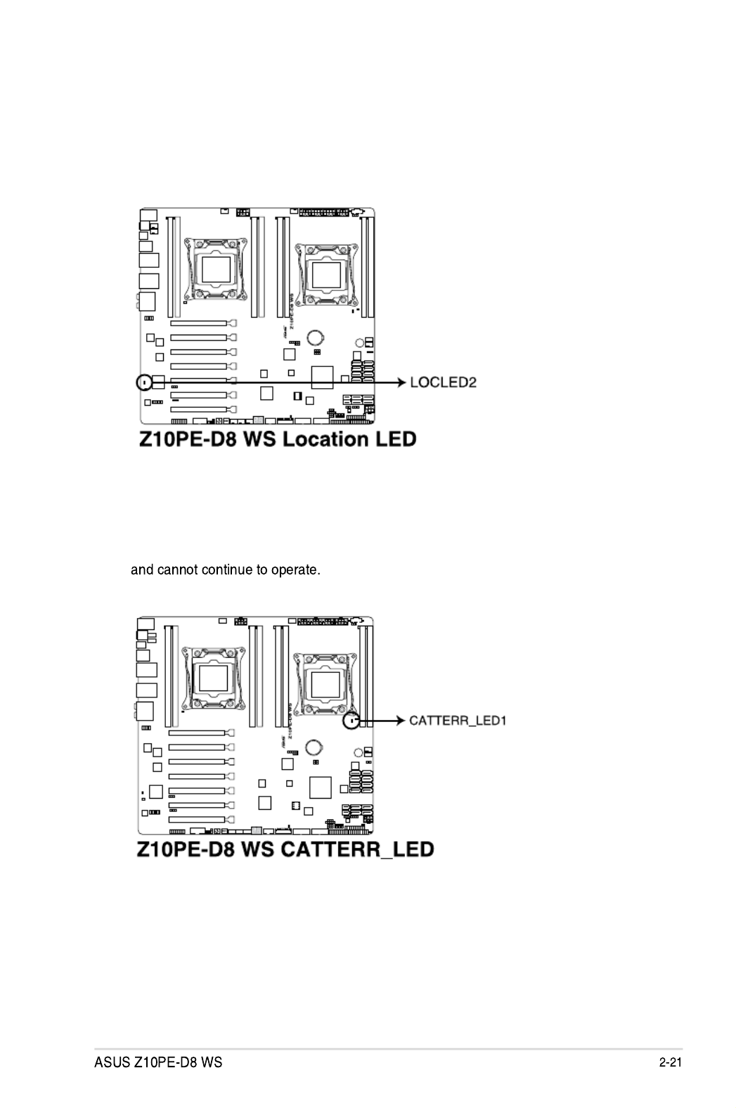
3. Location LED (LOCLED2)
ThisonboardLEDlightsupwhentheLocationbuttonontheserverispressedorwhen
triggeredbyasystemmanagementsoftware.TheLocationLEDhelpsvisuallylocate
andquicklyidentifytheserverinerroronaserverrack.
4. CATT LED (CATTERR_LED1)
TheCATTLEDindicatesthatthesystemhasexperiencedafatalorcatastrophicerror

2-22 Chapter 2: Hardware Information
5. CPU Warning LED (ERR_CPU1, ERR_CPU2)
6. M2 LED (M2_LED)
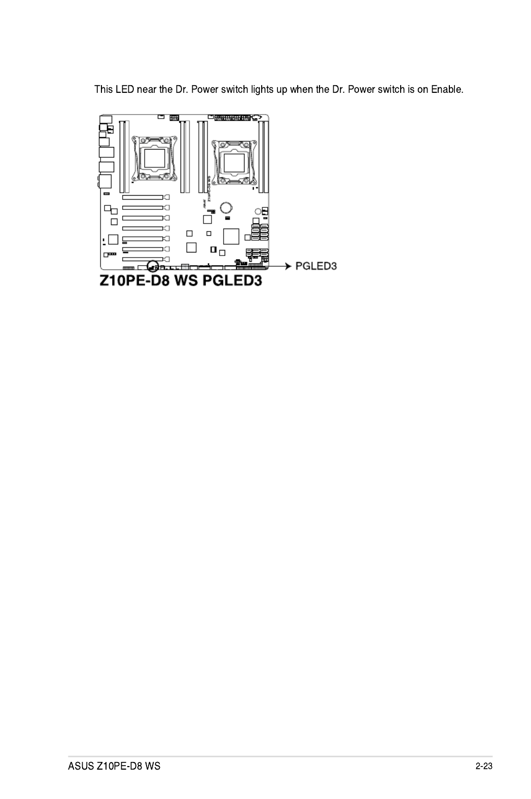
7. ASUS Dr. Power LED (PGLED3)

2-24 Chapter 2: Hardware Information
8. Q-Code LED (LED1)
TheQ-CodeLEDdesignprovidesyouthe2-digitdisplay,allowingyoutoknowthe
systemstatus.RefertotheQ-codetablebelowfordetails.
Code Description
00 Not used
01 Poweron.Resettypedetection(soft/hard).
02 APinitializationbeforemicrocodeloading
03 SystemAgentinitializationbeforemicrocodeloading
04 PCHinitializationbeforemicrocodeloading
06 Microcodeloading
07 APinitializationaftermicrocodeloading
08 SystemAgentinitializationaftermicrocodeloading
09 PCHinitializationaftermicrocodeloading
0A Initialization after microcode loading
0B Cacheinitialization
0C – 0D ReservedforfutureAMISECerrorcodes
0E Microcodenotfound
0F Microcodenotloaded
10 PEICoreisstarted
11 – 14 Pre-memoryCPUinitializationisstarted
15 – 18 Pre-memorySystemAgentinitializationisstarted
19 – 1C Pre-memoryPCHinitializationisstarted
2B – 2F Memoryinitialization
30 ReservedforASL(seeASLStatusCodessectionbelow)
Q-Code table

ASUS Z10PE-D8 WS 2-25
Code Description
31 MemoryInstalled
32 – 36 CPUpost-memoryinitialization
37 – 3A Post-MemorySystemAgentinitializationisstarted
3B – 3E Post-MemoryPCHinitializationisstarted
4F DXEIPLisstarted
50 – 53 Memoryinitializationerror.Invalidmemorytypeorincompatiblememoryspeed
54 Unspeciedmemoryinitializationerror
55 Memorynotinstalled
56 InvalidCPUtypeorSpeed
57 CPUmismatch
58 CPUselftestfailedorpossibleCPUcacheerror
59 CPUmicro-codeisnotfoundormicro-codeupdateisfailed
5A InternalCPUerror
5B ResetPPIisnotavailable
5C – 5F ReservedforfutureAMIerrorcodes
E0 S3Resumeisstared(S3ResumePPIiscalledbytheDXEIPL)
E1 S3BootScriptexecution
E2 Video repost
E3 OSS3wakevectorcall
E4 – E7 ReservedforfutureAMIprogresscodes
E8 S3ResumeFailed
E9 S3ResumePPInotFound
EA S3ResumeBootScriptError
EB S3OSWakeError
EC – EF ReservedforfutureAMIerrorcodes
F0 Recoveryconditiontriggeredbyrmware(Autorecovery)
F1 Recoveryconditiontriggeredbyuser(Forcedrecovery)
F2 Recoveryprocessstarted
F3 Recoveryrmwareimageisfound
F4 Recoveryrmwareimageisloaded
F5 – F7 ReservedforfutureAMIprogresscodes
F8 RecoveryPPIisnotavailable
F9 Recoverycapsuleisnotfound
FA Invalid recovery capsule
FB – FF ReservedforfutureAMIerrorcodes
60 DXECoreisstarted
61 NVRAMinitialization
62 InstallationofthePCHRuntimeServices
Q-Code table (continued)

2-26 Chapter 2: Hardware Information
Code Description
63 – 67 CPUDXEinitializationisstarted
68 PCIhostbridgeinitialization
69 SystemAgentDXEinitializationisstarted
6A SystemAgentDXESMMinitializationisstarted
6B – 6F SystemAgentDXEinitialization(SystemAgentmodulespecic)
70 PCHDXEinitializationisstarted
71 PCHDXESMMinitializationisstarted
72 PCHdevicesinitialization
73 – 77 PCHDXEInitialization(PCHmodulespecic)
78 ACPImoduleinitialization
79 CSMinitialization
7A – 7F ReservedforfutureAMIDXEcodes
90 BootDeviceSelection(BDS)phaseisstarted
91 Driver connecting is started
92 PCIBusinitializationisstarted
93 PCIBusHotPlugControllerInitialization
94 PCIBusEnumeration
95 PCIBusRequestResources
96 PCIBusAssignResources
97 ConsoleOutputdevicesconnect
98 Consoleinputdevicesconnect
99 SuperIOInitialization
9A USBinitializationisstarted
9B USBReset
9C USBDetect
9D USBEnable
9E – 9F ReservedforfutureAMIcodes
A0 IDEinitializationisstarted
A1 IDEReset
A2 IDEDetect
A3 IDEEnable
A4 SCSIinitializationisstarted
A5 SCSIReset
A6 SCSIDetect
A7 SCSIEnable
A8 SetupVerifyingPassword
A9 StartofSetup
AA ReservedforASL(seeASLStatusCodessectionbelow)
AB SetupInputWait
Q-Code table (continued)

ASUS Z10PE-D8 WS 2-27
Code Description
AC ReservedforASL(seeASLStatusCodessectionbelow)
AD ReadyToBootevent
AE LegacyBootevent
AF ExitBootServicesevent
B0 RuntimeSetVirtualAddressMAPBegin
B1 RuntimeSetVirtualAddressMAPEnd
B2 LegacyOptionROMInitialization
B3 SystemReset
B4 USBhotplug
B5 PCIbushotplug
B6 Clean-upofNVRAM
B7 CongurationReset(resetofNVRAMsettings)
B8– BF ReservedforfutureAMIcodes
D0 CPUinitializationerror
D1 SystemAgentinitializationerror
D2 PCHinitializationerror
D3 SomeoftheArchitecturalProtocolsarenotavailable
D4 PCIresourceallocationerror.OutofResources
D5 NoSpaceforLegacyOptionROM
D6 NoConsoleOutputDevicesarefound
D7 NoConsoleInputDevicesarefound
D8 Invalid password
D9 ErrorloadingBootOption(LoadImagereturnederror)
DA BootOptionisfailed(StartImagereturnederror)
DB Flash update is failed
DC Resetprotocolisnotavailable
Q-Code table (continued)
Code Description
0x01 SystemisenteringS1sleepstate
0x02 SystemisenteringS2sleepstate
0x03 SystemisenteringS3sleepstate
0x04 SystemisenteringS4sleepstate
0x05 SystemisenteringS5sleepstate
0x10 SystemiswakingupfromtheS1sleepstate
0x20 SystemiswakingupfromtheS2sleepstate
0x30 SystemiswakingupfromtheS3sleepstate
0x40 SystemiswakingupfromtheS4sleepstate
0xAC SystemhastransitionedintoACPImode.InterruptcontrollerisinPICmode.
0xAA SystemhastransitionedintoACPImode.InterruptcontrollerisinAPICmode.
ACPI/ASL Checkpoints

2-28 Chapter 2: Hardware Information
2.8 Jumpers
1. Clear RTC RAM (CLRTC1)
ThisjumperallowsyoutocleartheRealTimeClock(RTC)RAMinCMOS.Youcan
cleartheCMOSmemoryofdate,time,andsystemsetupparametersbyerasingthe
CMOSRTCRAMdata.TheonboardbuttoncellbatterypowerstheRAMdatain
CMOS,whichincludesystemsetupinformationsuchassystempasswords.
ToerasetheRTCRAM:
1. Turn OFF the computer and unplug the power cord.
2. Movethejumpercapfrompins1–2(default)topins2–3.Keepthecaponpins2–3
forabout5–10seconds,thenmovethecapbacktopins1–2.
3. Plug the power cord and turn ON the computer.
4. Holddownthe<Del>keyduringthebootprocessandenterBIOSsetuptore-
enter data.
ExceptwhenclearingtheRTCRAM,neverremovethecaponCLRTCjumperdefault
position.Removingthecapwillcausesystembootfailure!
Ifthestepsabovedonothelp,removetheonboardbatteryandmovethejumperagainto
cleartheCMOSRTCRAMdata.AftertheCMOSclearance,reinstallthebattery.
Especificaciones del producto
| Marca: | Asus |
| Categoría: | Placa madre |
| Modelo: | Z10PE-D8 WS |
¿Necesitas ayuda?
Si necesitas ayuda con Asus Z10PE-D8 WS haz una pregunta a continuación y otros usuarios te responderán
Placa madre Asus Manuales

11 Octubre 2024
7 Octubre 2024
2 Octubre 2024
30 Septiembre 2024
30 Septiembre 2024
29 Septiembre 2024
27 Septiembre 2024
21 Septiembre 2024
19 Septiembre 2024
19 Septiembre 2024
Placa madre Manuales
- Placa madre Sharkoon
- Placa madre Gigabyte
- Placa madre Asrock
- Placa madre Supermicro
- Placa madre Evga
- Placa madre Intel
- Placa madre MSI
- Placa madre ECS
- Placa madre NZXT
- Placa madre Foxconn
- Placa madre Elitegroup
- Placa madre EPoX
- Placa madre Biostar
Últimos Placa madre Manuales
27 Octubre 2024
27 Octubre 2024
27 Octubre 2024
27 Octubre 2024
27 Octubre 2024
27 Octubre 2024
27 Octubre 2024
27 Octubre 2024
20 Octubre 2024
19 Octubre 2024