BMW 328d xDrive Sports Wagon (2014) Manual de Usario
Lee a continuación 📖 el manual en español para BMW 328d xDrive Sports Wagon (2014) (244 páginas) en la categoría Auto. Esta guía fue útil para 20 personas y fue valorada con 4.5 estrellas en promedio por 2 usuarios
Página 1/244

Owner's Manual
for Vehicle
The Ultimate
Driving Machine
THE BMW 3 SERIES
SPORTS WAGON.
OWNER'S MANUAL.
Contents
A-Z
Online Edition for Part no. 01 40 2 925 793 - II/14


3 Series Owner's Manual for Vehicle
Thank you for choosing a BMW.
The more familiar you are with your vehicle, the better control
you will have on the road. We therefore strongly suggest:
Read this Owner's Manual before starting off in your new BMW.
Also use the Integrated Owner's Manual in your vehicle. It con‐
tains important information on vehicle operation that will help
you make full use of the technical features available in your
BMW. The manual also contains information designed to en‐
hance operating reliability and road safety, and to contribute to
maintaining the value of your BMW.
Any updates made after the editorial deadline for the printed or
Integrated Owner's Manual are located in the appendix of the
printed quick reference for the vehicle.
Supplementary information can be found in the additional bro‐
chures in the onboard literature.
We wish you a safe and enjoyable drive.
BMW AG
Online Edition for Part no. 01 40 2 925 793 - II/14

© 2014 Bayerische Motoren Werke
Aktiengesellschaft
Munich, Germany
Reprinting, including excerpts, only with the written
consent of BMW AG, Munich.
US English II/14, 03 14 490
Printed on environmentally friendly paper, bleached
without chlorine, suitable for recycling.
Online Edition for Part no. 01 40 2 925 793 - II/14

Contents
The fastest way to find information on a partic‐
ular topic or item is by using the index, refer to
page .234
6Notes
At a glance
12 Cockpit
16 iDrive
24 Voice activation system
27 Integrated Owner's Manual in the vehicle
Controls
32 Opening and closing
48 Adjusting
58 Transporting children safely
62 Driving
74 Displays
90 Lamps
95 Safety
115 Driving stability control systems
120 Driving comfort
142 Climate control
149 Interior equipment
159 Storage compartments
Driving tips
168 Things to remember when driving
171 Loading
174 Saving fuel
Mobility
184 Refueling
186 Fuel
191 Wheels and tires
199 Engine compartment
201 Engine oil
204 Coolant
205 Maintenance
207 Replacing components
219 Breakdown assistance
225 Care
Reference
232 Technical data
234 Everything from A to Z
Online Edition for Part no. 01 40 2 925 793 - II/14

Notes
Using this Owner's Manual
Orientation
The fastest way to find information on a partic‐
ular topic is by using the index.
An initial overview of the vehicle is provided in
the first chapter.
Updates made after the editorial
deadline
Any updates made after the editorial deadline
for the Owner's Manuals are located in the ap‐
pendix of the printed quick reference for the
vehicle.
User's manual for Navigation,
Entertainment, Communication
The topics of Navigation, Entertainment, Com‐
munication and the short commands of the
voice activation system are described in a sep‐
arate user's manual, which is also included
with the onboard literature.
Additional sources of information
The service center will be happy to answer any
other questions you may have.
Information on BMW, e.g., on technology, is
available on the Internet: www.bmwusa.com.
Symbols
Indicates precautions that must be followed
precisely in order to avoid the possibility of
personal injury and serious damage to the
vehicle.
◄ Marks the end of a specific item of
information.
"..." Identifies Control Display texts used to
select individual functions.
›...‹ Verbal instructions to use with the voice
activation system.
››...‹‹ Identifies the answers generated by the
voice activation system.
Refers to measures that can be taken to
help protect the environment.
Symbols on vehicle components
Indicates that you should consult the
relevant section of this Owner's Manual for
information on a particular part or assembly.
Vehicle equipment
This Owner's Manual describes all models and
all standard, country-specific and optional
equipment that is offered in the model series.
Therefore, in this Owner's Manual, equipment
is also described and illustrated that is not
available in your vehicle, e.g., because of the
selected optional equipment or the country-
specific variants.
This also applies for safety-related functions
and systems.
For any options and equipment not described
in this Owner's Handbook, refer to the Supple‐
mentary Owner's Handbooks.
On right-hand drive vehicles, some control ele‐
ments are arranged differently than shown in
the illustrations.
Status of the Owner's
Manual
Basic information
The manufacturer of your vehicle pursues a
policy of constant development that is con‐
ceived to ensure that our vehicles continue to
embody the highest quality and safety stan‐
Notes
6Online Edition for Part no. 01 40 2 925 793 - II/14

dards. In rare cases, therefore, the features de‐
scribed in this Owner's Manual may differ from
those in your vehicle.
Updates made after the editorial
deadline
Any updates made after the editorial deadline
for the Owner's Manuals are located in the ap‐
pendix of the printed quick reference for the
vehicle.
For your own safety
Warranty
Your vehicle is technically configured for the
operating conditions and registration require‐
ments applying in the country of first delivery -
homologation. If your vehicle is to be operated
in a different country it might be necessary to
adapt your vehicle to potentially differing oper‐
ating conditions and permit requirements. If
your vehicle does not comply with the homolo‐
gation requirements in a certain country you
cannot lodge warranty claims for your vehicle
there. Further information can be obtained
from your Service Centre.
Maintenance and repairs
Advanced technology, e.g., the use of modern
materials and high-performance electronics,
requires suitable maintenance and repair
methods.
Therefore, have this work performed only by a
BMW center or a workshop that works accord‐
ing to BMW repair procedures with appropri‐
ately trained personnel.
If this work is not carried out properly, there is
the danger of subsequent damage and related
safety hazards.
Parts and accessories
BMW recommends using parts and accesso‐
ries approved by BMW for this purpose.
Your BMW center is the right contact for genu‐
ine BMW parts and accessories, other prod‐
ucts approved by BMW and related qualified
advice.
BMW has tested these products for safety and
suitability in relation to BMW vehicles.
BMW can assume responsibility for them.
However, we cannot assume any responsibility
whatsoever for parts and accessories that have
not been specifically approved by BMW.
BMW cannot evaluate whether each individual
product from another manufacturer can be
used with BMW vehicles without presenting a
safety hazard. This guarantee is also not appli‐
cable when country-specific government ap‐
proval has been granted. Testing of this kind
may fail to embrace the entire range of poten‐
tial operating conditions to which components
might be exposed on BMW vehicles. Such
products could conceivably fail to comply with
BMW's own stringent quality standards.
California Proposition 65 Warning
California laws require us to state the following
warning:
Engine exhaust and a wide variety of automo‐
bile components and parts, including compo‐
nents found in the interior furnishings in a vehi‐
cle, contain or emit chemicals known to the
State of California to cause cancer and birth
defects and reproductive harm. In addition,
certain fluids contained in vehicles and certain
products of component wear contain or emit
chemicals known to the State of California to
cause cancer and birth defects or other repro‐
ductive harm. Battery posts, terminals and re‐
lated accessories contain lead and lead com‐
pounds. Wash your hands after handling. Used
engine oil contains chemicals that have caused
cancer in laboratory animals. Always protect
your skin by washing thoroughly with soap and
water.
Notes
7
Online Edition for Part no. 01 40 2 925 793 - II/14

Service and warranty
We recommend that you read this publication
thoroughly. Your vehicle is covered by the fol‐
lowing warranties:
▷New Vehicle Limited Warranty.
▷Rust Perforation Limited Warranty.
▷Federal Emissions System Defect War‐
ranty.
▷Federal Emissions Performance Warranty.
▷California Emission Control System Lim‐
ited Warranty.
Detailed information about these warranties is
listed in the Service and Warranty Information
Booklet for US models or in the Warranty and
Service Guide Booklet for Canadian models.
Your vehicle has been specifically adapted and
designed to meet the particular operating con‐
ditions and homologation requirements in your
country and continental region in order to de‐
liver the full driving pleasure while the vehicle
is operated under those conditions. If you wish
to operate your vehicle in another country or
region, you may be required to adapt your ve‐
hicle to meet different prevailing operating
conditions and homologation requirements.
You should also be aware of any applicable
warranty limitations or exclusions for such
country or region. In such case, please contact
Customer Relations for further information.
Maintenance
Maintain the vehicle regularly to sustain the
road safety, operational reliability and the New
Vehicle Limited Warranty.
Specifications for required maintenance meas‐
ures:
▷BMW Maintenance system
▷Service and Warranty Information Booklet
for US models
▷Warranty and Service Guide Booklet for
Canadian models
If the vehicle is not maintained according to
these specifications, this could result in seri‐
ous damage to the vehicle. Such damage is
not covered by the BMW New Vehicle Limited
Warranty.
Data memory
Many electronic components on your vehicle
are equipped with data memories that tempo‐
rarily or permanently store technical informa‐
tion about the condition of the vehicle, events
and faults. This technical information generally
documents the state of a component, a mod‐
ule, a system or the environment:
▷Operating states of system components,
fill levels for instance.
▷Status messages for the vehicle and from
its individual components, e.g., wheel rota‐
tion speed/ vehicle speed, deceleration,
transverse acceleration.
▷Malfunctions and faults in important sys‐
tem components, e.g., lights and brakes.
▷Responses by the vehicle to special situa‐
tions, e.g., deployment of an airbag, en‐
gagement of stability control systems.
▷Ambient conditions, such as temperature.
This data is purely technical in nature and is
used to detect and correct faults and to opti‐
mize vehicle functions. Motion profiles over
routes traveled cannot be created from this
data. When service offerings are used, e.g., re‐
pair services, service processes, warranty
claims, quality assurance, this technical infor‐
mation can be read out from the event and
fault memories by the service personnel, in‐
cluding the manufacturer, using special diag‐
nostic tools. You can obtain further information
there if it is needed. After a fault is corrected,
the information in the fault memory is deleted
or overwritten on a continuous basis.
When the vehicle is in use, situations are con‐
ceivable in which it might be possible to asso‐
ciate this technical data with individuals if it is
combined with other information, e.g., an acci‐
dent report, damage to the vehicle, eye wit‐
Notes
8Online Edition for Part no. 01 40 2 925 793 - II/14

ness accounts — possibly with the assistance
of an expert.
Additional functions that are contractually
agreed with the customer, such as vehicle lo‐
cating in an emergency, enable certain vehicle
data to be transmitted from the vehicle.
Event Data Recorder EDR
This vehicle is equipped with an event data re‐
corder EDR. The main purpose of an EDR is to
record, in certain crash or near crash-like situa‐
tions, such as an air bag deployment or hitting
a road obstacle, data that will assist in under‐
standing how a vehicle’s systems performed.
The EDR is designed to record data related to
vehicle dynamics and safety systems for a
short period of time, typically 30 seconds or
less.
The EDR in this vehicle is designed to record
such data as:
▷How various systems in your vehicle were
operating.
▷Whether or not the driver and passenger
safety belts were fastened.
▷How far, if at all, the driver was depressing
the accelerator and/or brake pedal.
▷How fast the vehicle was traveling.
These data can help provide a better under‐
standing of the circumstances in which
crashes and injuries occur.
EDR data are recorded by your vehicle only if a
nontrivial crash situation occurs; no data are
recorded by the EDR under normal driving
conditions and no personal data, e.g., name,
gender, age, and crash location, are recorded.
However, other parties, such as law enforce‐
ment, could combine the EDR data with the
type of personally identifying data routinely ac‐
quired during a crash investigation.
To read data recorded by an EDR, special
equipment is required, and access to the vehi‐
cle or the EDR is needed. In addition to the ve‐
hicle manufacturer, other parties, such as law
enforcement, that have the special equipment,
can read the information if they have access to
the vehicle or the EDR.
Reporting safety defects
For US customers
The following only applies to vehicles owned
and operated in the US.
If you believe that your vehicle has a defect
which could cause a crash or could cause in‐
jury or death, you should immediately inform
the National Highway Traffic Safety Adminis‐
tration NHTSA, in addition to notifying BMW of
North America, LLC, P.O. Box 1227, West‐
wood, New Jersey 07675-1227, Telephone
1-800-831-1117.
If NHTSA receives similar complaints, it may
open an investigation, and if it finds that a
safety defect exists in a group of vehicles, it
may order a recall and remedy campaign.
However, NHTSA cannot become involved in
individual problems between you, your dealer,
or BMW of North America, LLC.
To contact NHTSA, you may call the Vehicle
Safety Hotline toll-free at 1-888-327-4236
(TTY: 1-800-424-9153); go to http://
www.safercar.gov; or write to: Administrator,
NHTSA, 400 Seventh Street, SW., Washing‐
ton, DC 20590. You can also obtain other in‐
formation about motor vehicle safety from
http://www.safercar.gov.
For Canadian customers
Canadian customers who wish to report a
safety-related defect to Transport Canada, De‐
fect Investigations and Recalls, may telephone
the toll-free hotline 1-800-333-0510. You can
also obtain other information about motor vehi‐
cle safety from http://www.tc.gc.ca/roadsafety.
Notes
9
Online Edition for Part no. 01 40 2 925 793 - II/14
Online Edition for Part no. 01 40 2 925 793 - II/14

At a glance
These overviews of buttons, switches and
displays are intended to familiarize you with your
vehicle. You will also become quickly acquainted
with the available control concepts and options.
Online Edition for Part no. 01 40 2 925 793 - II/14
Cockpit
Vehicle equipment
All standard, country-specific and optional
equipment that is offered in the model series is
described in this chapter. Therefore, equip‐
ment is also described that is not available in a
vehicle, e. g., because of the selected optional
equipment or country variant. This also applies
for safety-related functions and systems.
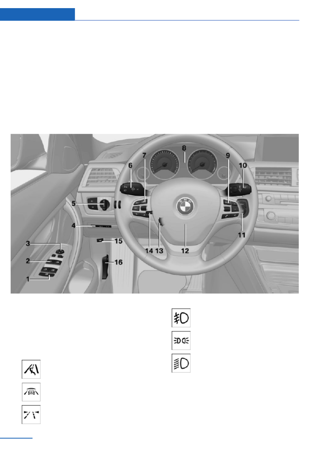
All around the steering wheel
1Rear window safety switch 45
2Power windows 44
3Exterior mirror operation 55
4Glove compartment on the driver's
side 159
Driver assistance systems
Active Blind Spot Detec‐
tion 112
Intelligent Safety 103
Lane departure warning 111
5Lamps
Front fog lamps 93
Parking lamps 90
Low beams 90
At a glance Cockpit
12 Online Edition for Part no. 01 40 2 925 793 - II/14

16 Unlock hood 200
All around the center console
1Headliner 15
2Control Display 16
3Ventilation 147
4Hazard warning system 219
Central locking system 37
5Glove compartment 159
6Radio/CD/Multimedia, see user's manual
for Navigation, Entertainment and Commu‐
nication
7Climate control 142
8Controller with buttons 16
9Parking brake 66
10 PDC Park Distance Control 129
Rearview camera 131
Parking assistant 137
Surround View 131
11 Driving Dynamics Control 117
DSC Dynamic Stability Con‐
trol 115
12 Automatic transmission selector
lever 70
Manual transmission selector lever 70
At a glance Cockpit
14 Online Edition for Part no. 01 40 2 925 793 - II/14

All around the headliner
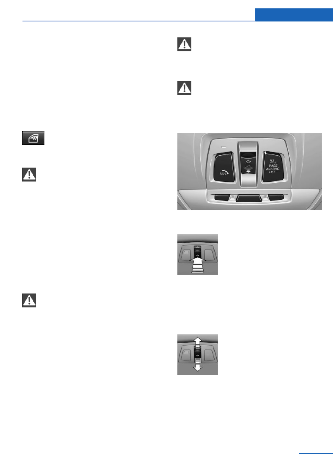
1Intelligent Emergency Re‐
quest 219
2Panoramic glass sunroof 45
3Indicator lamp, front passenger
airbag 97
4Reading lamps 93
5Interior lamps 93
Cockpit At a glance
15
Online Edition for Part no. 01 40 2 925 793 - II/14

iDrive
Vehicle equipment
All standard, country-specific and optional
equipment that is offered in the model series is
described in this chapter. Therefore, equip‐
ment is also described that is not available in a
vehicle, e. g., because of the selected optional
equipment or country variant. This also applies
for safety-related functions and systems.
The concept
The iDrive combines the functions of a multi‐
tude of switches. Thus, these functions can be
operated from a central location.
Using the iDrive during a trip
To avoid becoming distracted and pos‐
ing an unnecessary hazard to your vehicle's
occupants and to other road users, never at‐
tempt to use the controls or enter information
unless traffic and road conditions allow this.◀
Controls at a glance
Control elements
1Control Display
2Controller with buttons and, depending on
the equipment version, with touchpad
Control Display
Hints
▷To clean the Control Display, follow the
care instructions.
▷Do not place objects close to the Control
Display; otherwise, the Control Display can
be damaged.
Switching off
1. Press the button.
2. "Switch off control display"
Switching on
Press the controller again to switch the screen
back on.
Controller with navigation system
The buttons can be used to open the menus
directly. The controller can be used to select
menu items and create the settings.
Some iDrive functions can be operated using
the touchpad on the controller.
At a glance iDrive
16 Online Edition for Part no. 01 40 2 925 793 - II/14

1. Turn.
2. Press.
3. Move in four directions.
Buttons on controller
Press the but‐
ton
Function
MENU Open the main menu.
RADIO Opens the Radio menu.
MEDIA Opens the CD/Multimedia
menu.
NAV Opens the Navigation menu.
Press the but‐
ton
Function
TEL Opens the Telephone menu.
BACK Displays the previous panel.
OPTION Opens the Options menu.
Controller without navigation system
The buttons can be used to open the menus
directly. The controller can be used to select
menu items and create the settings.
1. Turn.
2. Press.
3. Move in two directions.
iDrive At a glance
17
Online Edition for Part no. 01 40 2 925 793 - II/14

Buttons on controller
Press the but‐
ton
Function
MENU Open the main menu.
Audio Open audio menu last lis‐
tened to, switch between au‐
dio menus.
TEL Opens the Telephone menu.
BACK Open previous panel.
OPTION Opens the Options menu.
Operating concept
Opening the main menu
Press the button.
The main menu is displayed.
All iDrive functions can be called up via the
main menu.
Selecting menu items
Highlighted menu items can be selected.
1. Turn the controller until the desired menu
item is highlighted.
2. Press the controller.
Menu items in the Owner's Manual
In the Owner's Manual, menu items that can be
selected are set in quotation marks, e.g.,
"Settings".
Changing between panels
After a menu item is selected, e.g., "Radio", a
new panel is displayed. Panels can overlap.
▷Move the controller to the left.
The current panel is closed and the previ‐
ous panel is displayed.
The previous panel is opened again by
pressing the BACK button. In this case, the
current panel is not closed.
▷Move the controller to the right.
A new panel is opened on top of the previ‐
ous display.
At a glance iDrive
18 Online Edition for Part no. 01 40 2 925 793 - II/14

White arrows pointing to the left or right indi‐
cate that additional panels can be opened.
View of an opened menu
When a menu is opened, it generally opens
with the panel that was last selected in that
menu. To display the first panel of a menu:
▷Move the controller to the left repeatedly
until the first panel is displayed.
▷Press the menu button on the controller
twice.
Opening the Options menu
Press the button.
The "Options" menu is displayed.
Additional options: move the controller to the
right repeatedly until the "Options" menu is
displayed.
Options menu
The "Options" menu consists of various areas:
▷Screen settings, e.g., "Split screen".
This area remains unchanged.
▷Control options for the selected main
menu, e.g., for "Radio".
▷If applicable, further operating options for
the selected menu, e.g., "Store station".
Changing settings
1. Select a field.
2. Turn the controller until the desired setting
is displayed.
3. Press the controller.
Activating/deactivating the functions
Several menu items are preceded by a check‐
box. It indicates whether the function is acti‐
vated or deactivated. Selecting the menu item
activates or deactivates the function.
The function is activated.
The function is deactivated.
Touchpad
Some iDrive functions can be operated using
the touchpad on the controller:
Selecting functions
1. "Settings"
2. "Touchpad"
3. Select the desired function.
▷"Speller": enter letters and numbers.
▷"Interactive map": operating the inter‐
active map.
▷"Browser": enter Internet addresses.
▷"Audio feedback": the entered letters
and numbers are announced.
Entering letters and numbers
The entry of the letters requires some practice
at the beginning. In the entry, pay attention to
the following:
iDrive At a glance
19
Online Edition for Part no. 01 40 2 925 793 - II/14

▷For the input of upper/lower case letters
and numbers, it may be necessary to
switch via the controller to the correspond‐
ing Input mode, refer to page , e.g.23
when the spelling of upper and lower case
letters is identical.
▷Enter characters as they are displayed on
the Control Display.
▷Always enter accompanying signs, such as
accents or periods so that the letter can be
clearly recognized. The possibility of input
depends on the set language. Where nec‐
essary, enter special characters via the
controller.
▷To delete a character, slide to the left on
the touchpad.
▷To enter a blank space, slide to the right in
the center of the touchpad.
▷To enter a hyphen, slide to the right in the
upper area of the touchpad.
▷To enter an underscore, slide to the right in
the lower area of the touchpad.
Using interactive map and Internet
The interactive map in the navigation system
and Internet sites can be moved via the touch‐
pad.
Function Controls
Move interactive map
or Internet sites.
Slide in the corre‐
sponding direction.
Enlarge/shrink interac‐
tive map or Internet
sites.
Drag inwards or
outwards on the
touchpad with the
fingers.
Display the menu or
open a link in the Inter‐
net.
Tap once.
Changing settings
Settings on the control display, such as the
volume, can be made via the touchpad. To do
this slide to the left or right accordingly.
Example: setting the clock
Setting the clock
1. Press the button. The main menu is
displayed.
2. Turn the controller until "Settings" is high‐
lighted, and then press the controller.
3. If necessary, move the controller to the left
to display "Time/Date".
4. Turn the controller until "Time/Date" is
highlighted, and then press the controller.
At a glance iDrive
20 Online Edition for Part no. 01 40 2 925 793 - II/14

5. Turn the controller until "Time:" is high‐
lighted, and then press the controller.
6. Turn the controller to set the hours and
press the controller.
7. Turn the controller to set the minutes and
press the controller.
Status information
Status field
The following information is displayed in the
status field at the top right:
▷Time.
▷Current entertainment source.
▷Sound output, on/off.
▷Wireless network reception strength.
▷Telephone status.
▷Traffic bulletin reception.
Status field symbols
The symbols are grouped as follows.
Radio symbols
Symbol Meaning
HD radio station is being received.
Satellite radio is switched on.
Telephone symbols
Symbol Meaning
Incoming or outgoing call.
Missed call.
Wireless network reception
strength.
Symbol flashes: network search.
Wireless network is not available.
Bluetooth is switched on.
Roaming is active.
Text message was received.
Check the SIM card.
SIM card is blocked.
SIM card is missing.
Enter the PIN.
Entertainment symbols
Symbol Meaning
CD/DVD player.
Music collection.
Gracenote® database.
AUX-IN port.
USB audio interface.
Mobile phone audio interface.
Additional symbols
Symbol Meaning
Spoken instructions are switched
off.
iDrive At a glance
21
Online Edition for Part no. 01 40 2 925 793 - II/14

Split screen
General information
Additional information can be displayed on the
right side of the split screen, e.g., information
from the onboard computer.
In the divided screen view, the so-called split
screen, this information remains visible even
when you change to another menu.
Switching the split screen on and off
1. Press the button.
2. "Split screen"
Selecting the display
1. Press the button.
2. "Split screen"
3. Move the controller until the split screen is
selected.
4. Press the controller or select "Split screen
content".
5. Select the desired menu item.
Programmable memory
buttons
General information
The iDrive functions can be stored on the pro‐
grammable memory buttons and called up di‐
rectly, e.g., radio stations, navigation destina‐
tions, phone numbers and entry points into the
menu.
The settings are stored for the remote control
currently in use.
Without navigation system and
telephone
Only radio stations can be stored on the but‐
tons, refer to user's manual for Navigation, En‐
tertainment, Communication.
Saving a function
1. Highlight the function via the iDrive.
2. Press the desired button for more
than 2 seconds.
Running a function
Press the button.
The function will run immediately. This
means, for example, that the number is dialed
when a phone number is selected.
Displaying the button assignment
Use a finger to touch the buttons. Do not wear
gloves or use objects.
The key assignment is displayed at the top
edge of the screen.
▷To display short information: touch the
button.
▷To display detailed information: touch the
button for an extended period.
At a glance iDrive
22 Online Edition for Part no. 01 40 2 925 793 - II/14

Deleting the button assignments
1. Press buttons 1 and 8 simultaneously for
approx. five seconds.
2. "OK"
Entering letters and numbers
General information
1. Turn the controller: select letters or num‐
bers.
2. Select additional letters or numbers if
needed.
3. "OK": confirm the entry.
Symbol Function
Press the controller: delete the let‐
ter or number.
Press the controller for an extended
period: delete all letters or numbers.
Switching between cases, letters and
numbers
Depending on the menu, you can switch be‐
tween entering upper and lower case, letters
and numbers:
Symbol Function
Enter the letters.
Enter the numbers.
or Move the controller up.
Without navigation system
Select the symbol.
Entry comparison
Entry of names and addresses: the selection is
narrowed down every time a letter is entered
and letters may be added automatically.
The entries are continuously compared to the
data stored in the vehicle.
▷Only those letters are offered during the
entry for which data is available.
▷Destination search: town/city names can
be entered using the spelling of language
available on the Control Display.
iDrive At a glance
23
Online Edition for Part no. 01 40 2 925 793 - II/14

Voice activation system
Vehicle equipment
All standard, country-specific and optional
equipment that is offered in the model series is
described in this chapter. Therefore, equip‐
ment is also described that is not available in a
vehicle, e. g., because of the selected optional
equipment or country variant. This also applies
for safety-related functions and systems.
The concept
▷Most functions that are displayed on the
Control Display can be operated by spoken
commands via the voice activation system.
The system prompts you to make your en‐
tries.
▷Functions that can only be used when the
vehicle is stationary cannot be operated
using the voice activation system.
▷The system uses a special microphone on
the driver's side.
▷›...‹ Verbal instructions in the Owner's
Manual to use with the voice activation
system.
Requirements
Via the Control Display, set a language that is
also supported by the voice activation system
so that the spoken commands can be identi‐
fied.
Set the language, refer to page .87
Using voice activation
Activating the voice activation system
1. Press the button on the steering
wheel.
2. Wait for the signal.
3. Say the command.
The command is displayed in the instru‐
ment cluster.
This symbol in the instrument cluster indi‐
cates that the voice activation system is active.
If no other commands are available, operate
the function in this case via iDrive.
Terminating the voice activation
system
Briefly press the button on the steer‐
ing wheel or ›End‹.
Possible commands
Most menu items on the Control Display can
be voiced as commands.
The available commands depend on which
menu is currently displayed on the Control Dis‐
play.
Short commands exist for many functions.
Some list entries, e.g., Phone book entries, can
also be selected via the voice activation sys‐
tem. Speak these list entries exactly as they
are displayed in the respective list.
Having possible commands read aloud
You can have the available commands read out
loud for you: ›commands‹
For example, if the "Settings" menu is dis‐
played, the commands for the settings are
read out loud.
At a glance Voice activation system
24 Online Edition for Part no. 01 40 2 925 793 - II/14

Executing functions using short
commands
Functions on the main menu can be performed
directly by means of short commands, nearly
irrespective of which menu item is currently
selected, e.g., ›Vehicle status‹.
List of short commands of the voice activation
system, see Navigation, Entertainment, Com‐
munication Owner's Manual.
Help dialog for the voice activation
system
Calling up help dialog: ›Help‹
Additional commands for the help dialog:
▷›Help with examples‹: information about the
current operating options and the most im‐
portant commands for them are an‐
nounced.
▷›Help voice activation‹: information about
the principle of operation for the voice acti‐
vation system is announced.
One example: open the tone
settings
Via the main menu
The commands of the menu items are spoken
just as they are selected via the controller.
1. Switch on the Entertainment sound output
if necessary.
2. Press the button on the steering
wheel.
3. ›Radio menu‹
4. ›Audio settings‹
Via short command
The desired radio station can also be started
via a short command.
1. Switch on the Entertainment sound output
if necessary.
2. Press the button on the steering
wheel.
3. ›Audio settings‹
Setting the voice dialog
You can set whether the system should use
the standard dialog or a shorter version.
In the shorter variant of the voice dialog, the
announcements from the system are issued in
an abbreviated form.
1. "Settings"
2. "Language/Units"
3. "Speech type:"
4. Select the setting.
Adjusting the volume
Turn the volume button while giving an in‐
struction until the desired volume is set.
▷The volume remains constant even if the
volume of other audio sources is changed.
▷The volume is stored for the remote con‐
trol currently in use.
Hints on Emergency
Requests
Do not use the voice activation system to ini‐
tiate an Emergency Request. In stressful situa‐
tions, the voice and vocal pitch can change.
Voice activation system At a glance
25
Online Edition for Part no. 01 40 2 925 793 - II/14

This can unnecessarily delay the establish‐
ment of a telephone connection.
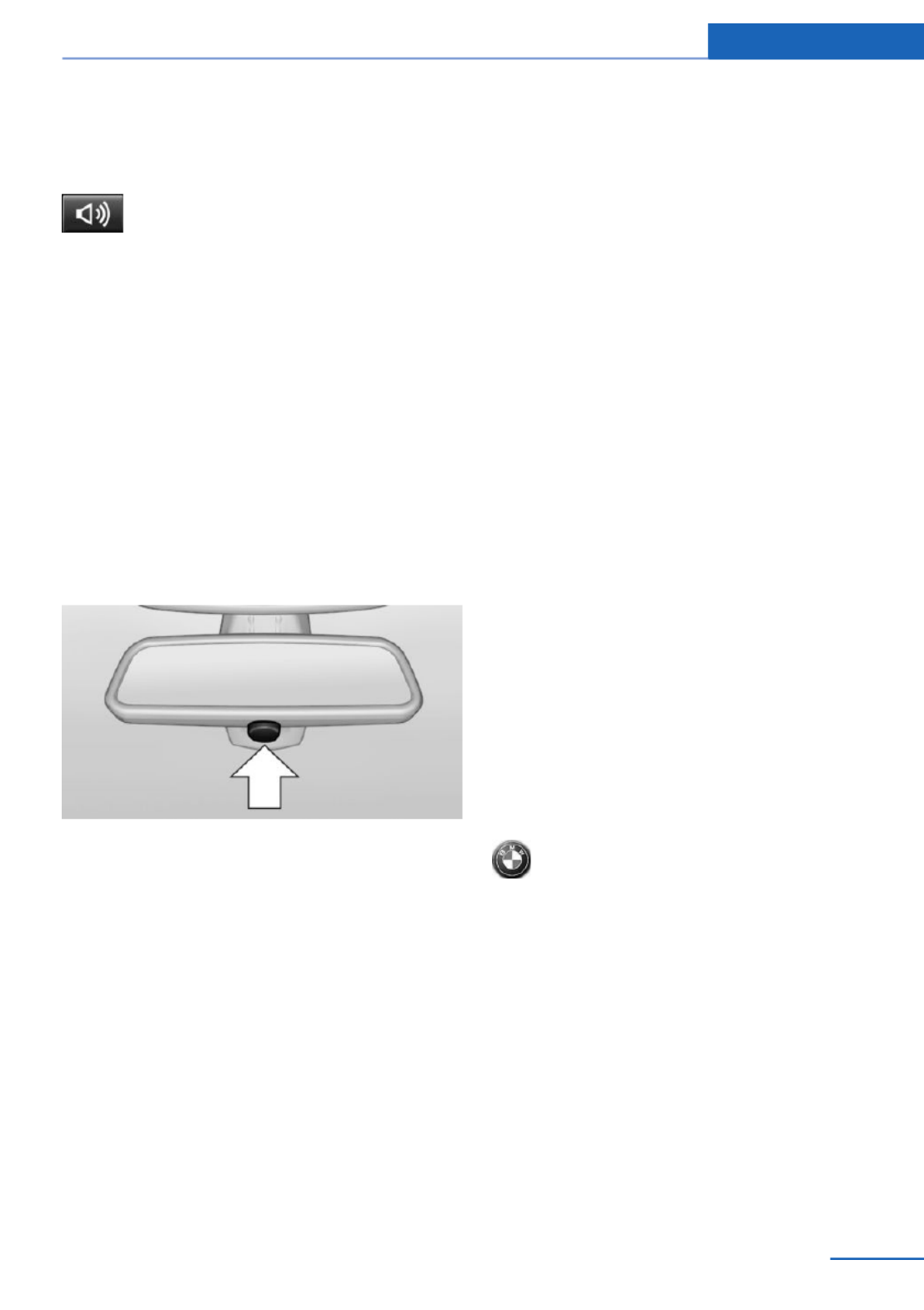
Instead, use the SOS button, refer to
page , in the vicinity of the interior mirror.219
Environmental conditions
▷Say the commands, numbers, and letters
smoothly and with normal volume, empha‐
sis, and speed.
▷Always say commands in the language of
the voice activation system.
▷Keep the doors, windows, and glass sun‐
roof closed to prevent noise interference.
▷Avoid making other noise in the vehicle
while speaking.
At a glance Voice activation system
26 Online Edition for Part no. 01 40 2 925 793 - II/14
Integrated Owner's Manual in the vehicle
Vehicle equipment
All standard, country-specific and optional
equipment that is offered in the model series is
described in this chapter. Therefore, equip‐
ment is also described that is not available in a
vehicle, e. g., because of the selected optional
equipment or country variant. This also applies
for safety-related functions and systems.
Integrated Owner's Manual
in the vehicle
The Integrated Owner's Manual can be dis‐
played on the Control Display. The equipment
and functions that are in the vehicle are descri‐
bed therein.
Components of the Integrated
Owner's Manual
The Integrated Owner's Manual consists of
three parts, which offer various levels of infor‐
mation or access possibilities.
Quick Reference Guide
Located in the Quick Reference is important
information for the operation of the vehicle, the
operation of basic vehicle functions or for what
to do in the event of a flat tire. This information
can also be displayed during driving.
Search by pictures
Information and descriptions based on illustra‐
tions can be searched via search by pictures.
This is helpful, for example, if the description of
an outfitting package that cannot be named is
needed.
Owner's Manual
Information and descriptions can be searched
by direct entry of a search term via the index.
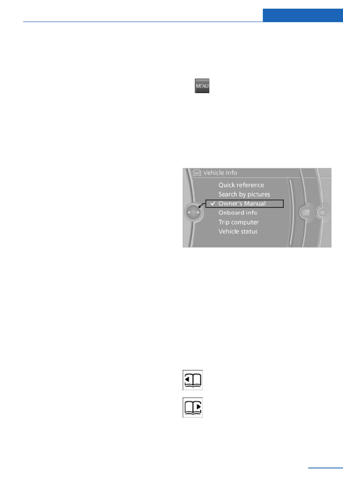
Select components
1. Press the button.
2. Turn the controller: open "Vehicle Info".
3. Press the controller.
4. Selecting desired range:
▷"Quick reference"
▷"Search by pictures"
▷"Owner's Manual"
Leafing through the Owner's Manual
Page by page with link access
Turn the controller until the next or previous
page is displayed.
Page by page without link access
Leaf through the pages directly while skipping
the links.
Highlight the symbol once. Now simply press
the controller to leaf from page to page.
Leaf back.
Leaf forward.
Integrated Owner's Manual in the vehicle At a glance
27
Online Edition for Part no. 01 40 2 925 793 - II/14

Context help - Owner's Manual to the
temporarily selected function
The relevant information can be opened di‐
rectly.
Opening via the iDrive
To move directly from the application on the
Control Display to the options menu:
1. Press the button or move the control‐
ler to the right repeatedly until the
"Options" menu is displayed.
2. "Display Owner's Manual"
Opening when a Check Control
message is displayed
Directly from the Check Control message on
the Control Display:
"Display Owner's Manual"
Changing between a function and the
Owner's Manual
To change from a function, e.g., radio, to the
Owner's Manual on the Control Display and to
switch between the two displays:
1. Press the button or move the control‐
ler to the right repeatedly until the
"Options" menu is displayed.
2. "Display Owner's Manual"
3. Select the desired page in the Owner's
Manual.
4. Press the button again to return to
the function displayed last.
5. Press the button to return to the page
of the Owner's Manual displayed last.
To switch back and forth repeatedly between
the function displayed last and the page of the
Owner's Manual displayed last, repeat steps 4
and 5. This opens a new panel every time.
Programmable memory buttons
General information
The Owner's Manual can be stored on the pro‐
grammable memory buttons and called up di‐
rectly.
Storing
1. "Owner's Manual" Select via the iDrive.
2. Press the desired button for more
than 2 seconds.
Executing
Press the button.
The Owner's Manual is displayed im‐
mediately.
At a glance Integrated Owner's Manual in the vehicle
28 Online Edition for Part no. 01 40 2 925 793 - II/14

Integrated Owner's Manual in the vehicle At a glance
29
Online Edition for Part no. 01 40 2 925 793 - II/14
Online Edition for Part no. 01 40 2 925 793 - II/14

Controls
This chapter is intended to provide you with
information that will give you complete control of
your vehicle. All features and accessories that
are useful for driving and your safety, comfort
and convenience are described here.
Online Edition for Part no. 01 40 2 925 793 - II/14

Opening and closing
Vehicle equipment
All standard, country-specific and optional
equipment that is offered in the model series is
described in this chapter. Therefore, equip‐
ment is also described that is not available in a
vehicle, e. g., because of the selected optional
equipment or country variant. This also applies
for safety-related functions and systems.
Remote control/key
General information
The vehicle is supplied with two remote con‐
trols with integrated keys.
Every remote control contains a replaceable
battery.
Depending on the equipment package and
country-specific variant, the functions of the
keys can be set. Settings, refer to page .41
For every remote control, personal settings are
stored in the vehicle. Personal Profile, refer to
page .33
Information on the required maintenance is
stored in the remote controls. Service data in
the remote control, refer to page .205
At a glance
1Unlocking
2Locking
3Unlock the tailgate
4Panic mode in alarm system
Integrated key
Press the button on the back of the remote
control, arrow 1, and pull out the key, arrow 2.
The integrated key fits the following locks:
▷Driver's door.
▷Glove compartment on the front passenger
side.
Replacing the battery
1. Take the integrated key out of the remote
control.
2. Push in the catch with the key, arrow 1.
3. Remove the cover of the battery compart‐
ment, arrow 2.
4. Insert a battery of the same type with the
positive side facing upwards.
5. Press the cover closed.
Controls Opening and closing
32 Online Edition for Part no. 01 40 2 925 793 - II/14

Take the used battery to a recycling
center or to your service center.
New remote controls
New remote controls are available from the
service center.
Loss of the remote controls
Lost remote controls can be blocked by your
service center.
Emergency detection of remote
control
It is possible to switch on the ignition or start
the engine in situations such as the following:
▷Interference of radio transmission to re‐
mote control by external sources, e.g. by
radio masts.
▷Discharged battery in the remote control.
▷Interference of radio transmission by mo‐
bile devices in close proximity to the re‐
mote control.
▷Interference of radio transmission by
charger while charging items such as mo‐
bile devices in the vehicle.
A Check Control message is displayed if an at‐
tempt is made to switch on the ignition or start
the engine.
Starting the engine with emergency
detection of the remote control
Automatic transmission: if a corresponding
Check Control message appears, hold the re‐
mote control, as shown, against the marked
area on the steering column and press the
Start/Stop button within 10 seconds while
pressing the brake.
Manual transmission: if a corresponding Check
Control message appears, hold the remote
control, as shown, against the marked area on
the steering column and press the Start/Stop
button within 10 seconds while pressing the
clutch pedal.
Personal Profile
The concept
Individual settings in the vehicle are saved in
personal profiles. Every remote control is as‐
signed a profile.
Three personal profiles and a guest profile can
be created.
▷Changes to the settings are automatically
saved in the profile currently activated.
▷During unlocking, the profile stored for the
remote control is activated.
▷Your personal settings will be recognized
and called up again even if the vehicle has
been operated in the meantime with an‐
other remote control.
Adjusting
The following settings are stored in a profile.
▷Radio: stored stations, station listened to
last.
▷Assignment of the programmable memory
buttons.
▷Tone settings.
▷Audio source listened to last.
▷Unlocking the vehicle: driver door or entire
vehicle.
▷Locking the vehicle: if no door is open or
after starting off.
▷Welcome lamps: on/off.
Opening and closing Controls
33
Online Edition for Part no. 01 40 2 925 793 - II/14

▷Triple turn signal activation: on/off.
▷Headlamp courtesy delay feature: time set‐
ting.
▷Language on the Control Display.
▷Daytime running lights: on/off.
▷Automatic climate control/Automatic cli‐
mate control with enhanced features: set‐
tings.
▷Navigation: map views, route criteria, voice
output on/off.
▷Park Distance Control PDC: adjusting the
signal tone volume.
▷Rearview camera: selection of functions
and type of display.
▷Side view: display type.
▷Head-up Display: selection, brightness,
position and rotation of the display.
▷Driving Dynamics Control: sport program.
▷Exterior mirror position.
▷Driver's seat position: automatically re‐
trieved after unlocking.
▷Collision warning: warning time.
▷Lane departure warning: last setting, on/
off.
▷Active Blind Spot Detection: last setting,
on/off.
Profile management
Opening the profiles
A different profile can be called up than the
one associated with the remote control cur‐
rently in use.
1. "Settings"
2. "Profiles"
3. Select a profile.
Called up profile is assigned to the remote
control being used at the time.
Renaming profiles
1. "Settings"
2. "Profiles"
3. Open "Options".
4. "Rename current profile"
Resetting profiles
The settings of the active profile are reset to
their default values.
1. "Settings"
2. "Profiles"
3. Open "Options".
4. "Reset current profile"
Exporting profiles
Most settings of the active profile and the
saved contacts can be exported.
This can be helpful for securing and retrieving
personal settings, before delivering the vehicle
to a workshop for example. The saved profiles
can be taken with you to another vehicle
equipped with the Personal Profile function.
The following export options are available:
▷BMW Online.
▷Via the USB port to a USB device.
Popular file systems for USB devices are
supported. FAT32 and exFAT are the rec‐
ommended formats for profile export.
Other formats may not support the export.
1. "Settings"
2. "Profiles"
3. "Export profile"
4. BMW Online: "BMW Online"
USB interface: "USB device"
Controls Opening and closing
34 Online Edition for Part no. 01 40 2 925 793 - II/14

Importing profiles
Existing settings and contacts are overwritten
with the imported profile.
1. "Settings"
2. "Profiles"
3. "Import profile"
4. BMW Online: "BMW Online"
USB interface: "USB device"
Using the guest profile
The guest profile can be used to make individ‐
ual settings that are saved in none of the three
personal profiles.
This can be useful for drivers who are using
the vehicle temporarily and do not have their
own profile.
1. "Settings"
2. "Profiles"
3. Open "Guest".
The guest profile cannot be renamed. It is not
assigned to the current remote control.
Display profile list during start
The profile list can be displayed during each
start for selecting the desired profile.
1. "Settings"
2. "Profiles"
3. Open "Options".
4. "Display user list at startup"
Using the remote control
Note
Take the remote control with you
People or animals left unattended in a
parked vehicle can lock the doors from the in‐
side. Always take the remote control with you
when leaving the vehicle so that the vehicle
can then be opened from the outside.◀
Unlocking
Press the button on the remote con‐
trol.
The vehicle is unlocked.
Welcome lamps, interior lamp and courtesy
lamps are switched on.
You can set how the vehicle is to be unlocked.
Performing settings, refer to page .41
The alarm system, refer to page , is dis‐42
armed.
Convenient opening
The remote control can be used to open the
windows and the glass sunroof after unlocking.
Press and hold the button on the re‐
mote control.
Releasing the button stops the motion.
Locking
Press the button on the remote control.
Locking from the outside
Do not lock the vehicle from the outside
if there are people in it, as the vehicle cannot
be unlocked from inside without special knowl‐
edge.◀
The alarm system, refer to page , is armed.42
Switching on interior lamps and
courtesy lamps
Press the button on the remote control
with the vehicle locked.
If the button is pressed again within 10 sec‐
onds of the vehicle being locked, the interior
motion sensor and tilt alarm sensor of the anti-
theft warning system, refer to page , are43
switched off. After locking, wait 10 seconds
before pressing the button again.
Opening and closing Controls
35
Online Edition for Part no. 01 40 2 925 793 - II/14

Panic mode
You can trigger the alarm system if you find
yourself in a dangerous situation.
Press the button on the remote con‐
trol for at least 3 seconds.
To switch off the alarm: press any button.
Opening the tailgate
Press the button on the remote con‐
trol for approx. 1 second.
The tailgate opens automatically, regardless of
whether the vehicle is locked or unlocked.
Note the opening height of the tailgate
The tailgate pivots back and up when it
opens. Ensure that there is sufficient clearance
when the tailgate opens; otherwise, damage
may result.◀
Depending on how the vehicle is equipped and
the country-specific variant, you can set
whether the doors are also unlocked.
Do not place the remote control in the
cargo area
Take the remote control with you and do not
leave it in the cargo area; otherwise, the re‐
mote control is locked inside the vehicle when
the tailgate is closed.◀
Provide edge protection
Sharp or angular objects can hit the rear
window while driving and damage the heating
wires of the rear window. Provide edge protec‐
tion.◀
Malfunction
If the vehicle can no longer be locked or un‐
locked with the remote control, the battery
may be discharged or there may be interfer‐
ence from external sources such as mobile
phones, metal objects, overhead power lines,
transmission towers, etc.
In this case, lock/unlock the vehicle without the
remote control, refer to page .36
For US owners only
The transmitter and receiver units comply with
part 15 of the FCC/Federal Communication
Commission regulations. Operation is gov‐
erned by the following:
FCC ID:
▷LX8766S.
▷LX8766E.
▷LX8CAS.
▷LX8CAS2.
▷MYTCAS4.
Compliance statement:
This device complies with part 15 of the FCC
Rules. Operation is subject to the following
two conditions:
▷This device may not cause harmful inter‐
ference, and
▷this device must accept any interference
received, including interference that may
cause undesired operation.
Any unauthorized modifications or changes to
these devices could void the user's authority to
operate this equipment.
Without remote control
From the outside
Locking from the outside
Do not lock the vehicle from the outside
if there are people in it, as the vehicle cannot
be unlocked from inside without special knowl‐
edge.◀
Remove the key before pulling the door
handle
Before pulling the outside door handle, remove
the key to avoid damaging the paintwork and
the key.◀
Controls Opening and closing
36 Online Edition for Part no. 01 40 2 925 793 - II/14

Unlock or lock the driver's door via the door
lock using the integrated key. The other doors
must be unlocked or locked from the inside.
Alarm system
The alarm system is not armed if the vehicle is
locked with the integrated key.
The alarm system is triggered when the door is
opened, if the vehicle was unlocked via the
door lock. In order to terminate this alarm, un‐
lock vehicle with the remote control or switch
on the ignition, if necessary, by emergency de‐
tection of the remote control.
From the inside
Locking and unlocking
Pressing the button for the central locking sys‐
tem locks and unlocks the tailgate and the rear
window when the front doors are closed, but
they are not secured against theft.
The fuel filler flap remains unlocked.
In the event of an accident of corresponding
severity, the vehicle is automatically unlocked.
The hazard warning system and interior lamps
come on.
Unlocking and opening
▷Either unlock the doors together using the
button for the central locking system and
then pull the door handle above the arm‐
rest or
▷Pull the door opener twice individually on
each door: the first time unlocks the door,
the second time opens it.
Tailgate
Automatic tailgate operation
Adjusting the opening height
You can set how far the tailgate should open.
Adjusting the opening height
When adjusting the opening height, en‐
sure that there is a clearance of at least
4 in/10 cm above the tailgate. Otherwise, the
ceiling may not be high enough for the open
tailgate if the load situation changes.◀
1. "Settings"
2. "Tailgate"
3. Turn the controller until the desired open‐
ing height is selected.
Opening
The tailgate pivots back and up when it opens.
Ensure that adequate clearance is available
before opening.
Opening and closing Controls
37
Online Edition for Part no. 01 40 2 925 793 - II/14

Note the opening height of the tailgate
The tailgate pivots back and up when it
opens. Ensure that there is sufficient clearance
when the tailgate opens; otherwise, damage
may result.
Adjust the opening height of the tailgate ac‐
cording to the given situation.◀
The tailgate opens automatically to the ad‐
justed opening height.
▷Press the button on the exterior of the tail‐
gate.
▷Press the button on the remote
control for approx. 1 second.
▷Push the button in the driver's
footwell.
The tailgate is opened if the vehicle is sta‐
tionary, provided that the tailgate has not
been locked.
Pressing the button again stops the motion.
The opening process is interrupted as well:
▷When starting the engine.
▷When the vehicle starts moving.
▷By pressing the button in the driver's foot‐
well.
▷By pressing the button on the inside of the
tailgate.
Provide edge protection
Sharp or angular objects can hit the rear
window while driving and damage the heating
wires of the rear window. Provide edge protec‐
tion.◀
Closing
Without Comfort Access:
▷Press the button on the inside of the tail‐
gate.
The tailgate closes automatically.
Pressing the button again stops the mo‐
tion.
With Comfort Access:
▷Press the button, arrow 1, on the inside of
the tailgate.
The tailgate closes automatically.
Pressing the button again stops the mo‐
tion.
▷Press the button, arrow 2.
Tailgate closes automatically and the vehi‐
cle is locked.
Controls Opening and closing
38 Online Edition for Part no. 01 40 2 925 793 - II/14

▷Press the button on the exterior of the tail‐
gate.
Pressing the button again stops the mo‐
tion.
The closing operation is interrupted:
▷When starting the engine.
▷The vehicle starts off with jerks.
Keep the closing path clear
Make sure that the closing path of the
tailgate is clear; otherwise, injuries may re‐
sult.◀
Do not place the remote control in the
cargo area
Take the remote control with you and do not
leave it in the cargo area; otherwise, the re‐
mote control is locked inside the vehicle when
the tailgate is closed.◀
Manual operation
In the event of an electrical malfunction, oper‐
ate the unlocked tailgate manually with a slow
and smooth motion.
Do not operate the tailgate manually if it
is blocked
If the tailgate is blocked, do not operate it man‐
ually as the tailgate may otherwise become
damaged and injury may result.
Contact your service center.◀
Opening and closing the rear window
Small objects can be loaded and unloaded
quickly by opening the rear window separately.
Press the button next to the rear window.
The rear window opens slightly and can be
swung upward.
To close, press the window closed.
Provide edge protection
Sharp or angular objects can hit the rear
window while driving and damage the heating
wires of the rear window. Provide edge protec‐
tion.◀
Comfort Access
The concept
The vehicle can be accessed without activat‐
ing the remote control.
All you need to do is to have the remote con‐
trol with you, such as in your pants pocket.
The vehicle automatically detects the remote
control when it is nearby or in the passenger
compartment.
Comfort Access supports the following func‐
tions:
▷Unlocking/locking of the vehicle.
▷Convenient closing.
▷Unlocking of the tailgate separately.
▷Start the engine.
Functional requirements
▷There are no external sources of interfer‐
ence nearby.
Opening and closing Controls
39
Online Edition for Part no. 01 40 2 925 793 - II/14

▷To lock the vehicle, the remote control
must be located outside of the vehicle.
▷The next unlocking and locking cycle is not
possible until after approx. 2 seconds.
▷The engine can only be started if the re‐
mote control is in the vehicle.
Comparison with ordinary remote
control
The functions can be controlled by pressing
the buttons of the remote control or Comfort
Access.
Unlocking
Grasp the door handle on the driver's or front
passenger door completely, arrow.
This corresponds to pressing the button
on the remote control.
Locking
Press the area on the door handle, arrow, with
your finger for approx. 1 second without grasp‐
ing the door handle.
This corresponds to pressing the button
on the remote control.
To save battery power, ensure that the ignition
and all electronic systems and/or power con‐
sumers are switched off before locking the ve‐
hicle.
Convenient closing
Press the area on the door handle, arrow, with
your finger and hold it down.
In addition to locking, the windows and the
glass sunroof are closed.
Monitor the closing process
Monitor the closing process to ensure
that no one becomes trapped.◀
Unlocking the tailgate separately
Press the button on the exterior of the tailgate.
This corresponds to pressing the but‐
ton on the remote control.
Do not place the remote control in the
cargo area
Take the remote control with you and do not
leave it in the cargo area; otherwise, the re‐
mote control is locked inside the vehicle when
the tailgate is closed.◀
Opening tailgate with no-touch
activation
With Comfort Access and automatic tailgate
operation, the tailgate can be opened with no-
contact activation using the remote control
you are carrying.
Two sensors detect a forward-directed foot
motion in the center of the area at the rear of
the car and the tailgate opens.
Controls Opening and closing
40 Online Edition for Part no. 01 40 2 925 793 - II/14

Foot movement to be carried out
Do not touch vehicle
With the foot motion, make sure there is
steady stance and do not touch the vehicle;
otherwise, there is a danger of injury, e. g. from
hot exhaust system parts.◀
1. Place in the center behind the vehicle,
about an arm's length from the vehicle rear.
2. Move a foot in the direction of travel as far
under the vehicle as possible and immedi‐
ately pull it back. With this movement, the
leg must pass through the ranges of both
sensors.
Opening
The tailgate opens, regardless of whether it
was previously locked or unlocked.
The tailgate pivots back and up when it opens.
Ensure that adequate clearance is available
before opening.
Before the opening, the hazard warning sys‐
tem flashes.
Preventing inadvertent opening
In situations where the tailgate should
not be opened with no-touch activation, en‐
sure that the remote control is located beyond
the range of the sensor, at least 5 ft/1.50 m
from the rear of the car.
Otherwise, the tailgate may be opened inad‐
vertently, for example by an unintentional or
misinterpreted movement of the foot.◀
Malfunction
Comfort Access may not function properly if it
experiences interference from external sour‐
ces such as mobile phones, metal objects,
overhead power lines, transmission towers,
etc.
In this case, open or close the vehicle using the
buttons on the remote control or use the
integrated key in the door lock.
If there is a malfunction, open the tailgate with
the remote control button or with the button on
the tailgate.
Adjusting
Unlocking
The setting is stored for the remote control
currently in use.
1. "Settings"
2. "Doors/key"
3. Select symbol or "Unlock button:"
4. Select the desired function:
▷"Driver's door only"
Only the driver's door and the fuel filler
flap are unlocked. Pressing again un‐
locks the entire vehicle.
▷"All doors"
The entire vehicle is unlocked.
Depending on how the vehicle is equipped or
the country-specific variant, you can set
whether the doors are also unlocked with the
button on the remote control.
Confirmation signals from the vehicle
The setting is stored for the remote control
currently in use.
1. "Settings"
2. "Doors/key"
3. Deactivate or activate the desired confir‐
mation signals.
Opening and closing Controls
41
Online Edition for Part no. 01 40 2 925 793 - II/14

▷"Acoustic sig. lock/unlock"
▷"Flash when lock/unlock"
Automatic locking
The setting is stored for the remote control
currently in use.
1. "Settings"
2. "Doors/key"
3. Select the desired function:
▷"Lock if no door is opened"
The vehicle locks automatically after a
short period of time if a door is not
opened.
▷"Lock after start driving"
The vehicle locks automatically after
you drive away.
Retrieving the seat and mirror settings
The driver's seat and exterior mirror positions
used last are stored for the remote control cur‐
rently in use.
When the vehicle is unlocked, these positions
are automatically retrieved if this function was
activated.
Pinch hazard when moving back the seat
If this function is used, first make sure
that the footwell behind the driver's seat is
empty. Otherwise, people can be injured or ob‐
jects damaged when the seat is moved back.◀
The adjustment procedure is interrupted:
▷When a seat position switch is pressed.
▷When a button of the seat and mirror mem‐
ory is pressed.
Activating the setting
1. "Settings"
2. "Doors/key"
3. "Last seat position autom."
Alarm system
The concept
The vehicle alarm system responds to:
▷Opening of a door, the hood or the tailgate
or rear window.
▷Movements in the vehicle.
▷Changes in the vehicle tilt, e.g., during at‐
tempts to steal a wheel or when towing the
car.
▷Interruptions in battery voltage.
The alarm system briefly indicates tampering:
▷By sounding an acoustic alarm.
▷By switching on the hazard warning sys‐
tem.
▷By flashing the daytime running lights.
Arming and disarming the alarm
system
General information
When you lock or unlock the vehicle, either
with the remote control or via the Comfort Ac‐
cess at the door lock, the alarm system is
armed or disarmed at the same time.
Door lock and armed alarm system
The alarm system is triggered when the door is
opened, if the vehicle is unlocked via the door
lock.
In order to terminate this alarm, unlock vehicle
with the remote control or switch on the igni‐
tion, if necessary, by emergency detection of
the remote control.
Tailgate and armed alarm system
The tailgate can be opened even when the
alarm system is armed.
After the tailgate is closed, it is locked and
monitored again if the doors are locked. The
hazard warning system flashes once.
Controls Opening and closing
42 Online Edition for Part no. 01 40 2 925 793 - II/14
Panic mode
You can trigger the alarm system if you find
yourself in a dangerous situation.
Press the button on the remote con‐
trol for at least 3 seconds.
To switch off the alarm: press any button.
Switching off the alarm
To terminate the alarm:
▷Unlock the vehicle using the remote con‐
trol.
▷With Comfort Access: If you are carrying
the remote control with you, grasp the
driver side or front passenger side door
handle completely.
Indicator lamp on the interior rearview
mirror
▷The indicator lamp flashes briefly every
2 seconds:
The system is armed.
▷The indicator lamp flashes after locking:
The doors, hood, tailgate or rear window is
not closed properly, but the rest of the ve‐
hicle is secured.
After 10 seconds, the indicator lamp
flashes continuously. Interior motion sen‐
sor and tilt alarm sensor are not active.
▷The indicator lamp goes out after unlock‐
ing:
The vehicle has not been tampered with.
▷The indicator lamp flashes after unlocking
until the engine ignition is switched on, but
no longer than approx. 5 minutes:
An alarm has been triggered.
Tilt alarm sensor
The tilt of the vehicle is monitored.
The alarm system responds in situations such
as attempts to steal a wheel or when the car is
towed.
Interior motion sensor
The windows and glass sunroof must be
closed for the system to function properly.
Avoiding unintentional alarms
The tilt alarm sensor and interior motion sen‐
sor can be switched off together, such as in
the following situations:
▷In automatic car washes.
▷In duplex garages.
▷During transport on car-carrying trains, at
sea or on a trailer.
▷When animals are to remain in the vehicle.
Switching off the tilt alarm sensor and
interior motion sensor
Press the remote control button again
within 10 seconds as soon as the vehicle
is locked.
The indicator lamp lights up for approx. 2 sec‐
onds and then continues to flash.
The tilt alarm sensor and interior motion sen‐
sor are switched off until the vehicle is locked
again.
Opening and closing Controls
43
Online Edition for Part no. 01 40 2 925 793 - II/14

Power windows
General information
Take the remote control with you
Take the remote control with you when
leaving the vehicle so that children, for exam‐
ple, cannot operate the power windows and in‐
jure themselves.◀
Opening
▷ Press the switch to the resistance
point.
The window opens while the switch is held.
▷ Press the switch beyond the resist‐
ance point.
The window opens automatically.
Pressing the switch again stops the motion.
Convenient opening, refer to page , via the35
remote control.
Closing
Keep the closing path clear
Monitor the closing process and make
sure that the closing path of the window is
clear; otherwise, injuries may result.◀
▷ Pull the switch to the resistance
point.
The window closes while the switch is
held.
▷ Pull the switch beyond the resistance
point.
The window closes automatically.
Pressing the switch stops the motion.
Closing via Comfort Access, refer to page .39
Pinch protection system
If the closing force exceeds a specific value as
a window closes, the closing action is inter‐
rupted.
The window reopens slightly.
Danger of pinching even with pinch pro‐
tection
Even with the pinch protection system, check
that the window's closing path is clear; other‐
wise, the closing action may not stop in certain
situations, e.g., if thin objects are present.◀
No window accessories
Do not install any accessories in the
range of movement of the windows; otherwise,
the pinch protection system will be impaired.◀
Closing without the pinch protection
system
Keep the closing path clear
Monitor the closing process and make
sure that the closing path of the window is
clear; otherwise, injuries may result.◀
For example, if there is an external danger or if
ice on the windows prevents a window from
closing normally, proceed as follows:
1. Pull the switch past the resistance point
and hold it there.
The pinch protection is limited and the
window reopens slightly if the closing force
exceeds a certain value.
2. Pull the switch past the resistance point
again within approx. 4 seconds and hold it
there.
Controls Opening and closing
44 Online Edition for Part no. 01 40 2 925 793 - II/14
The window closes without pinch protec‐
tion.
Safety switch
The safety switch in the driver's door can be
used to prevent children, for example, from
opening and closing the rear windows using
the switches in the rear.
Switching on and off
Press the button.
The LED lights up if the safety func‐
tion is switched on.
Safety switch for rear operation
Press the safety switch when transport‐
ing children in the rear; otherwise, injury may
result if the windows are closed without super‐
vision.◀
Roller sunblinds
Roller sunblinds for the rear side
windows
Pull out the roller sunblind at the loop and hook
it onto the bracket.
Do not open the window while the roller
sunblind is raised.
Do not open the window while the roller sun‐
blind is raised; otherwise, there is a risk of
damage at high speeds that may result in per‐
sonal injury.◀
Panoramic glass sunroof
General information
The glass sunroof and the sliding visor can be
operated together or separately, using the
same switch.
The glass sunroof is operational when the igni‐
tion is switched on.
Keep the closing path clear
Monitor the closing process and make
sure that the closing path of the glass sunroof
is clear; otherwise, injuries may result.◀
Take the remote control with you
Take the remote control with you when
leaving the vehicle so that children, for exam‐
ple, cannot operate the roof and injure them‐
selves.◀
Tilting the glass sunroof
Push switch upward briefly.
▷The closed roof is tilted and
the sliding visor opens
slightly.
▷The opened roof closes until
it is in its tilted position. The
sliding visor stays com‐
pletely open.
Opening/closing the sliding visor
▷Press the switch in the de‐
sired direction to the resist‐
ance point and hold it there.
The sliding visor moves
while the switch is being
held.
▷Press the switch in the desired direction
past the resistance point.
The sliding visor moves automatically.
Pressing the switch again stops the mo‐
tion.
Opening and closing Controls
45
Online Edition for Part no. 01 40 2 925 793 - II/14

Opening/closing the glass sunroof
When the sliding visor is open, proceed as de‐
scribed under Sliding visor.
Opening/closing the glass sunroof and
sliding visor together
Briefly press the switch twice in
succession in the desired direc‐
tion past the resistance point.
The glass sunroof and sliding vi‐
sor move together. Pressing the
switch again stops the motion.
Convenient opening, refer to page , via the35
remote control.
Convenient closing, refer to page , with40
Comfort Access.
Comfort position
Stops the roof in the comfort position if the
roof is not fully open. This reduces wind noise
in the passenger compartment.
If desired, continue the movement by pressing
the switch.
Pinch protection system
If the closing force when closing the glass sun‐
roof exceeds a certain value, the closing move‐
ment is stopped, beginning at approximately
the middle of the opening in the roof, or from
the tilted position during closing.
The glass sunroof opens again slightly.
Danger of pinching even with pinch pro‐
tection
Despite the pinch protection system, check
that the roof's closing path is clear; otherwise,
the closing action may not be interrupted in
certain extreme situations, such as when thin
objects are present.◀
Closing from the open position
without pinch protection
For example, if there is an external danger, pro‐
ceed as follows:
1. Press the switch forward beyond the re‐
sistance point and hold.
Pinch protection is limited and the roof re‐
opens slightly if the closing force exceeds
a certain value.
2. Press the switch forward again beyond the
resistance point and hold until the roof
closes without pinch protection. Make sure
that the closing area is clear.
Closing from the raised position
without pinch protection
If there is an external danger, push the switch
forward past the resistance point and hold it.
The roof closes without pinch protection.
Initializing after a power failure
After a power failure during the opening or
closing process, the roof can only be operated
to a limited extent.
Initializing the system
The system can be initialized when the vehicle
is stationary and the engine is running.
During the initialization, the roof closes without
pinch protection.
Keep the closing path clear
Monitor the closing process and make
sure that the closing path of the glass sunroof
is clear; otherwise, injuries may result.◀
Press the switch up and hold it
until the initialization is com‐
plete:
▷Initialization begins within
15 seconds and is com‐
pleted when the sunroof and
sliding visor are completely
closed.
Controls Opening and closing
46 Online Edition for Part no. 01 40 2 925 793 - II/14

▷The roof closes without pinch protection.
Opening and closing Controls
47
Online Edition for Part no. 01 40 2 925 793 - II/14
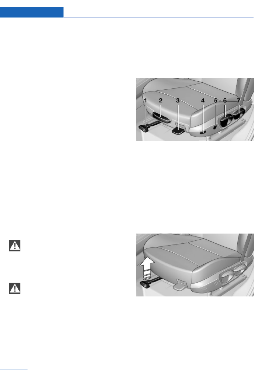
Adjusting
Vehicle equipment
All standard, country-specific and optional
equipment that is offered in the model series is
described in this chapter. Therefore, equip‐
ment is also described that is not available in a
vehicle, e. g., because of the selected optional
equipment or country variant. This also applies
for safety-related functions and systems.
Sitting safely
The ideal seating position can make a vital
contribution to relaxed, fatigue-free driving.
The seating position plays an important role in
an accident in combination with:
▷Safety belts, refer to page .51
▷Head restraints, refer to page .52
▷Airbags, refer to page .95
Seats
Hints
Do not adjust the seat while driving
Do not adjust the driver's seat while driv‐
ing, or the seat could respond with unexpected
movement and the ensuing loss of vehicle
control could lead to an accident.◀
Do not incline the backrest too far to the
rear
Also on the front passenger side, do not incline
the backrest on the front passenger side too
far to the rear during driving, or there is a risk of
slipping under the safety belt in the event of an
accident. This would eliminate the protection
normally provided by the belt.◀
Manually adjustable seats
At a glance
1Forward/backward
2Thigh support
3Seat tilt
4Backrest width
5Lumbar support
6Height
7Backrest tilt
Forward/backward
Pull the lever and slide the seat in the desired
direction.
After releasing the lever, move the seat for‐
ward or back slightly to make sure it engages
properly.
Controls Adjusting
48 Online Edition for Part no. 01 40 2 925 793 - II/14

Height
Pull the lever and apply your weight to the seat
or lift it off, as necessary.
Backrest tilt
Pull the lever and apply your weight to the
backrest or lift it off, as necessary.
Seat tilt
Pull the lever and move the seat to the desired
tilt. After releasing the lever, apply your weight
to the seat or lift it off to make sure the seat
engages properly.
Electrically adjustable seats
At a glance
1Seat and mirror memory
2Backrest width
3Lumbar support
4Backrest tilt
5Forward/backward, height, seat tilt
Note
The seat setting for the driver's seat is stored
for the remote control currently in use. When
the vehicle is unlocked via the remote control,
the position is automatically retrieved if the
function, refer to page , is activated for this42
purpose.
Adjustments in detail
1. Forward/back.
Adjusting Controls
49
Online Edition for Part no. 01 40 2 925 793 - II/14

2. Height.
3. Seat tilt.
4. Backrest tilt.
Thigh support
Pull the lever at the front of the seat and adjust
the thigh support.
Lumbar support
The curvature of the seat backrest can be ad‐
justed in such a way that it supports the lumbar
region of the spine. The lower back and the
spine are supported for upright posture.
▷Press the front/rear section
of the switch.
The curvature is increased/
decreased.
▷Press the upper/lower sec‐
tion of the switch.
The curvature is shifted up/
down.
Backrest width
Change the width of the back‐
rest using the side wings to ad‐
just the lateral support.
Controls Adjusting
50 Online Edition for Part no. 01 40 2 925 793 - II/14

Front seat heating
Switching on
Press the button once for each tem‐
perature level.
The maximum temperature is reached when
three LEDs are lit.
If the drive is continued within approx. 15 mi‐
nutes, the seat heating is activated automati‐
cally with the temperature selected last.
When ECO PRO, refer to page , is acti‐175
vated, the heater output is reduced.
Switching off
Press the button longer.
The LEDs go out.
Rear seat heating
Switching on
Press the button once for each tem‐
perature level.
The maximum temperature is reached when
three LEDs are lit.
If the drive is continued within approx. 15 mi‐
nutes, the seat heating is activated automati‐
cally with the temperature selected last.
When ECO PRO, refer to page , is acti‐175
vated, the heater output is reduced.
Switching off
Press the button longer.
The LEDs go out.
Safety belts
Seats with safety belt
The vehicle has five seats, each of which is
equipped with a safety belt.
Number of safety belts
Your vehicle has been fitted with five safety
belts for the safety of you and your passen‐
gers. However, they can only offer protection
when adjusted correctly.
Hints
Always make sure that safety belts are being
worn by all occupants before driving away.
To protect the occupants, the belt locking trig‐
gers early. Slowly guide the belt out of the
holder when applying it.
Although airbags enhance safety by providing
added protection, they are not a substitute for
safety belts.
▷The upper shoulder strap's anchorage
point will be correct for adult seat occu‐
pants of every build if the seat is correctly
adjusted.
▷The two outer safety belt buckles,
integrated into the rear seat, are for pas‐
sengers sitting on the left and right.
▷The center rear seat belt buckle is solely
intended for the center passenger.
Adjusting Controls
51
Online Edition for Part no. 01 40 2 925 793 - II/14
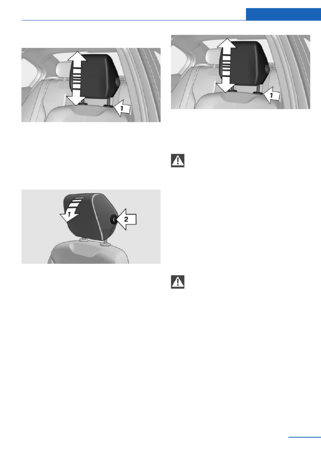
Adjusting the height
▷To raise: pull.
▷To lower: press the button, arrow 1, and
push the head restraint down.
Tilt
Three different tilt positions are available.
▷Forward: pull the top edge of the head re‐
straint forward, arrow 1.
▷Back: press the button, arrow 2. The head
restraint folds as far back as possible.
Removing
Only remove the head restraint if no one will be
sitting in the seat in question.
1. Pull the head restraint upward as far as
possible.
2. Press the button, arrow 1, and pull the
head restraint out completely.
Before transporting passengers
Reinstall the head restraint before trans‐
porting anyone in the seat; otherwise, the pro‐
tective function of the head restraint is unavail‐
able.◀
Rear head restraints
Correctly adjusted head restraint
A correctly adjusted head restraint reduces the
risk of injury to cervical vertebrae in the event
of an accident.
Adjusting the head restraint
Correctly adjust the head restraints of all
occupied seats; otherwise, there is an in‐
creased risk of injury in an accident.◀
Height
Adjust the head restraint so that its center is
approximately at ear level.
Adjusting Controls
53
Online Edition for Part no. 01 40 2 925 793 - II/14

Adjusting the height
▷To raise: pull.
▷To lower: press the button, arrow 1, and
push the head restraint down.
The center head restraint cannot be adjusted
in elevation.
Folding down head restraints
Extending/retracting head restraint
Only fold down head restraint if no pas‐
sengers are in the rear. Fold out retracted
headrests again if passengers are being car‐
ried in the rear; otherwise, there is increased
risk of injury in the event of an accident.◀
▷To lower flaps: press the button, arrow 1,
and press down the head restraint, arrow 2.
▷Fold back up: pull up head restraints.
Removing
Only remove the head restraint if no one will be
sitting in the seat in question.
1. Pull the head restraint upward as far as
possible.
2. Press the button, arrow 1, and pull the
head restraint out completely.
Before transporting passengers
Reinstall the head restraint before trans‐
porting anyone in the seat; otherwise, the pro‐
tective function of the head restraint is unavail‐
able.◀
Seat and mirror memory
Hints
Do not retrieve the memory while driving
Do not retrieve the memory setting while
driving, as an unexpected movement of the
seat could result in an accident.◀
Keep the movement area unobstructed
When changing the seat position, keep
the seat's area of movement unobstructed;
otherwise, people can be injured or objects
damaged.◀
Controls Adjusting
54 Online Edition for Part no. 01 40 2 925 793 - II/14

General information
Two different driver's seat and exterior mirror
positions can be stored and retrieved for each
remote control. Settings for the backrest width
and lumbar support are not stored in memory.
Storing
1. Switch on the ignition.
2. Set the desired position.
3. Press the button. The LED in the
button lights up.
4. Press the desired button 1 or 2. The LED
goes out.
If the M button is pressed accidentally:
Press the button again.
The LED goes out.
Calling up settings
Comfort function
1. Open the driver's door.
2. Switch off the ignition.
3. Briefly press the desired button 1 or 2.
The corresponding seat position is performed
automatically.
The procedure stops when a switch for adjust‐
ing the seat or one of the buttons is pressed.
Safety mode
1. Close the driver's door or switch on the ig‐
nition.
2. Press and hold the desired button 1 or 2
until the adjustment procedure is com‐
pleted.
Calling up of a seat position
deactivated
After a brief period, the calling up of stored
seat positions is deactivated to save battery
power.
To reactivate calling up of a seat position:
▷Open or close the door or tailgate.
▷Press a button on the remote control.
▷Press the Start/Stop button.
Mirrors
Exterior mirrors
At a glance
1Adjusting
2Left/right, Automatic Curb Monitor
3Fold in and out
General information
The mirror on the passenger side is more
curved than the driver's side mirror.
Estimating distances correctly
Objects reflected in the mirror are closer
than they appear. Do not estimate the distance
to the traffic behind you based on what you
see in the mirror, as this will increase your risk
of an accident.◀
Adjusting Controls
55
Online Edition for Part no. 01 40 2 925 793 - II/14
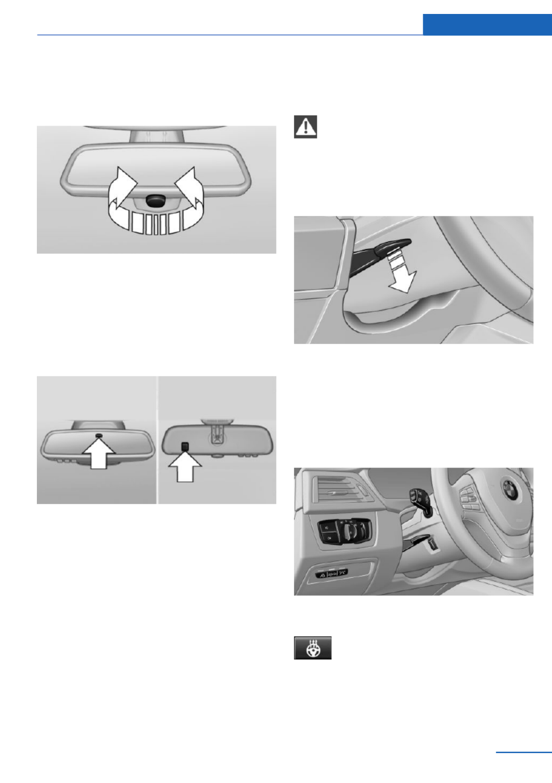
Interior rearview mirror, manually
dimmable
Turn knob
Turn the knob to reduce the blinding effect by
the interior mirror.
Interior rearview mirror, automatic
dimming feature
The concept
Photocells are used for control:
▷In the mirror glass.
▷On the back of the mirror.
Functional requirement
For proper operation:
▷Keep the photocells clean.
▷Do not cover the area between the inside
rearview mirror and the windshield.
Steering wheel
General information
Do not adjust while driving
Do not adjust the steering wheel while
driving; otherwise, an unexpected movement
could result in an accident.◀
Adjusting
1. Fold the lever down.
2. Move the steering wheel to the preferred
height and angle to suit your seating posi‐
tion.
3. Fold the lever back.
Steering wheel heating
Switching on/off
Press the button.
▷On: the LED lights up.
▷Off: the LED goes out.
Adjusting Controls
57
Online Edition for Part no. 01 40 2 925 793 - II/14

Transporting children safely
Vehicle equipment
All standard, country-specific and optional
equipment that is offered in the model series is
described in this chapter. Therefore, equip‐
ment is also described that is not available in a
vehicle, e. g., because of the selected optional
equipment or country variant. This also applies
for safety-related functions and systems.
The right place for children
Note
Children in the vehicle
Do not leave children unattended in the
vehicle; otherwise, they could endanger them‐
selves and other persons, e.g., by opening the
doors.◀
Children should always be in the rear
Accident research shows that the safest place
for children is in the back seat.
Transporting children in the rear
Only transport children younger than
13 years of age or shorter than 5 ft/150 cm in
the rear in child restraint fixing systems pro‐
vided in accordance with the age, weight and
size of the child; otherwise, there is an in‐
creased risk of injury in an accident.
Children 13 years of age or older must wear a
safety belt as soon as a suitable child restraint
fixing system can no longer be used, due to
their age, weight and size.◀
Children on the front passenger seat
Should it ever be necessary to use a child re‐
straint fixing system in the front passenger
seat, make sure that the front, knee and side
airbags on the front passenger side are deacti‐
vated. Automatic deactivation of front passen‐
ger airbags, refer to page .97
Note
Deactivated front passenger airbags
If a child restraint fixing system is used in
the front passenger seat, the front passenger
airbags must be deactivated; otherwise, there
is an increased risk of injury to the child when
the airbags are triggered, even with a child re‐
straint fixing system.◀
Installing child restraint
fixing systems
Before mounting
Before mounting child restraint fixing systems,
ensure that the rear seat backrests are locked.
Hints
Manufacturer's information for child re‐
straint fixing systems
To select, mount and use child restraint fixing
systems, observe the information provided by
the system manufacturer; otherwise, the pro‐
tective effect can be impaired.◀
Ensuring the stability of the child seat
When installing child restraint fixing sys‐
tems, make sure that the child seat is securely
fastened to the backrest of the seat. The angle
of the backrest may need to be adjusted and,
where necessary, the headrest height may also
need to be adjusted, or if possible removed.
Make sure that all backrests are securely
locked. Otherwise, the stability of the child
seat is limited, and there is an increased risk of
injury because of unexpected movement of the
rear seat backrest.◀
Controls Transporting children safely
58 Online Edition for Part no. 01 40 2 925 793 - II/14
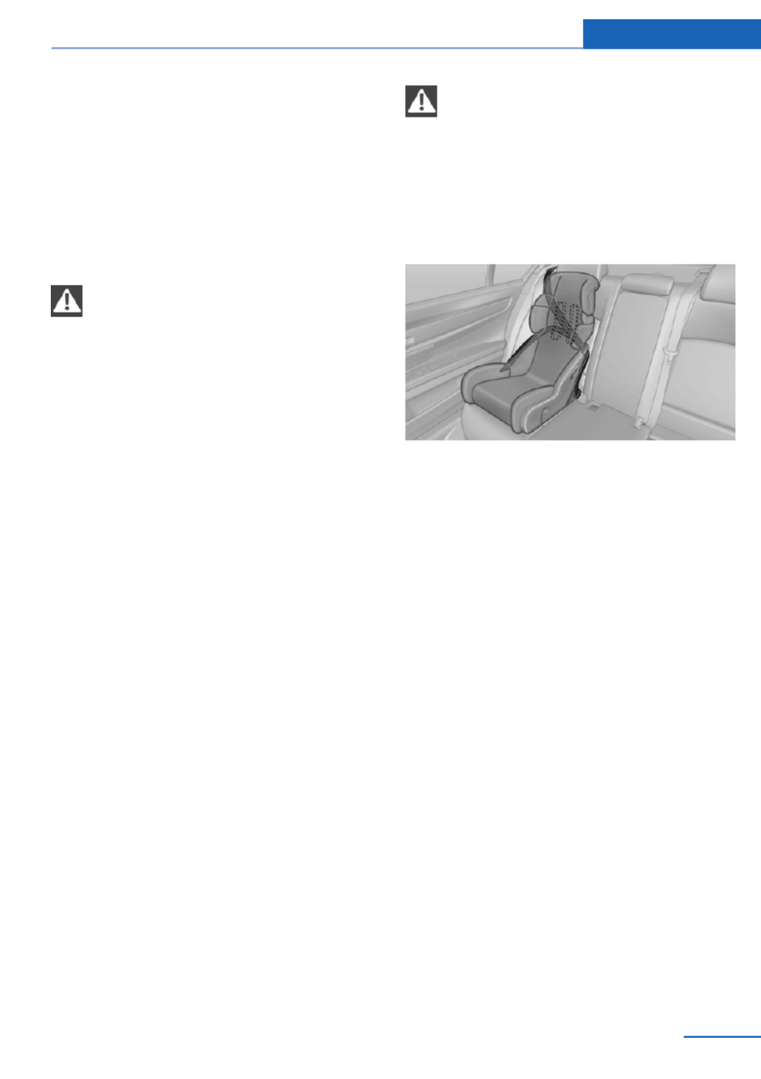
On the front passenger seat
Deactivating airbags
After installing a child restraint fixing system in
the front passenger seat, make sure that the
front, knee and side airbags on the front pas‐
senger side are deactivated.
Deactivate the front passenger airbags auto‐
matically, refer to page .97
Deactivating the front passenger airbags
If a child restraint fixing system is used in
the front passenger seat, the front passenger
airbags must be deactivated; otherwise, there
is an increased risk of injury to the child when
the airbags are triggered, even with a child re‐
straint fixing system.◀
Seat position and height
Before installing a child restraint fixing system,
move the front passenger seat as far back as
possible and adjust its height to the highest
position to obtain the best possible position for
the belt and to offer optimal protection in the
event of an accident.
If the upper fixing point of the safety belt is lo‐
cated before the belt guide of the child seat,
move the passenger seat carefully forward un‐
til the best possible belt guide position is
reached.
Backrest width
Adjustable backrest width: before installing a
child restraint fixing system in the front pas‐
senger seat, open the backrest width com‐
pletely. Do not change the backrest width
again and do not call up a memory position.
Backrest width for the child seat
Before installing a child restraint fixing
system in the front passenger seat, the back‐
rest width must be opened completely. Do not
change the adjustment after this; otherwise,
the stability of the child seat will be reduced.◀
Child seat security
The rear safety belts and the front passenger
safety belt can be locked against pulling out for
mounting the child restraint fixing systems.
Locking the safety belt
1. Pull out the belt webbing completely.
2. Secure the child restraint fixing system
with the belt.
3. Allow the belt webbing to be pulled in and
pull it taut against the child restraint fixing
system. The safety belt is locked.
Unlocking the safety belt
1. Unbuckle the belt buckle.
2. Remove the child restraint fixing system.
3. Allow the belt webbing to be pulled in com‐
pletely.
LATCH child restraint fixing system
LATCH: Lower Anchors and Tether for Chil‐
dren.
Transporting children safely Controls
59
Online Edition for Part no. 01 40 2 925 793 - II/14

Note
Follow manufacturer's information for
LATCH child restraint fixing systems
To mount and use the LATCH child restraint
fixing systems, observe the operating and
safety information from the system manufac‐
turer; otherwise, the level of protection may be
reduced.◀
Mounts for the lower LATCH anchors
The lower anchors may be used to attach the
CRS to the vehicle seat up to a combined child
and CRS weight of 65 lb/30 kg when the child
is restrained by the internal harnesses.
Correctly engage the lower LATCH an‐
chors
Make sure that the lower LATCH anchors have
properly engaged and that the child restraint
fixing system is resting snugly against the
backrest; otherwise, the degree of protection
offered may be reduced.◀
Before mounting the LATCH child restraint fix‐
ing system, pull the belt away from the child
restraint fixing system.
Position
Mounts for the lower LATCH anchors are lo‐
cated behind the indicated covers.
Mounting ISOFIX child restraint fixing
systems
1. Mount the child restraint fixing system; re‐
fer to the user's manual of the system.
2. Ensure that both LATCH anchors are prop‐
erly connected.
Child restraint fixing system with a
tether strap
Mounting points
There are three mounting points for the upper
retaining strap of LATCH child restraint fixing
systems.
Note
Mounting eyes
Only use the mounting eyes for the up‐
per retaining strap to secure child restraint fix‐
ing systems; otherwise, the mounting eyes
could be damaged.◀
Retaining strap guide
Retaining strap
Make sure that the upper retaining strap
is not routed over the head restraints or sharp
edges and is free of twisting on its way to the
upper mounting point; otherwise, the belt can‐
not properly secure the child restraint fixing
system in an accident.◀
Controls Transporting children safely
60 Online Edition for Part no. 01 40 2 925 793 - II/14

1 Direction of travel
2 Head restraint.
3 Hook for upper retaining strap
4 Mounting point/eye
5 Seat backrest
6 Upper retaining strap
Attaching the upper retaining strap to
the mounting point
1. Raise the head restraint if necessary.
2. Guide the upper retaining strap between
the supports of the head restraint.
3. If there is a retaining strap, run it between
the backrest and the cargo cover.
4. Attach the hook of the retaining strap to
the mounting eye.
5. Tighten the retaining strap by pulling it
down.
6. Lower and lock head restraints as needed.
Locking the doors and
windows
Rear doors
Push the locking lever on the rear doors down.
The door can now be opened from the outside
only.
Safety switch for the rear
Press the button on the driver's door if
children are being transported in the
rear.
This locks various functions so that they can‐
not be operated from the rear: safety switch,
refer to page .45
Transporting children safely Controls
61
Online Edition for Part no. 01 40 2 925 793 - II/14
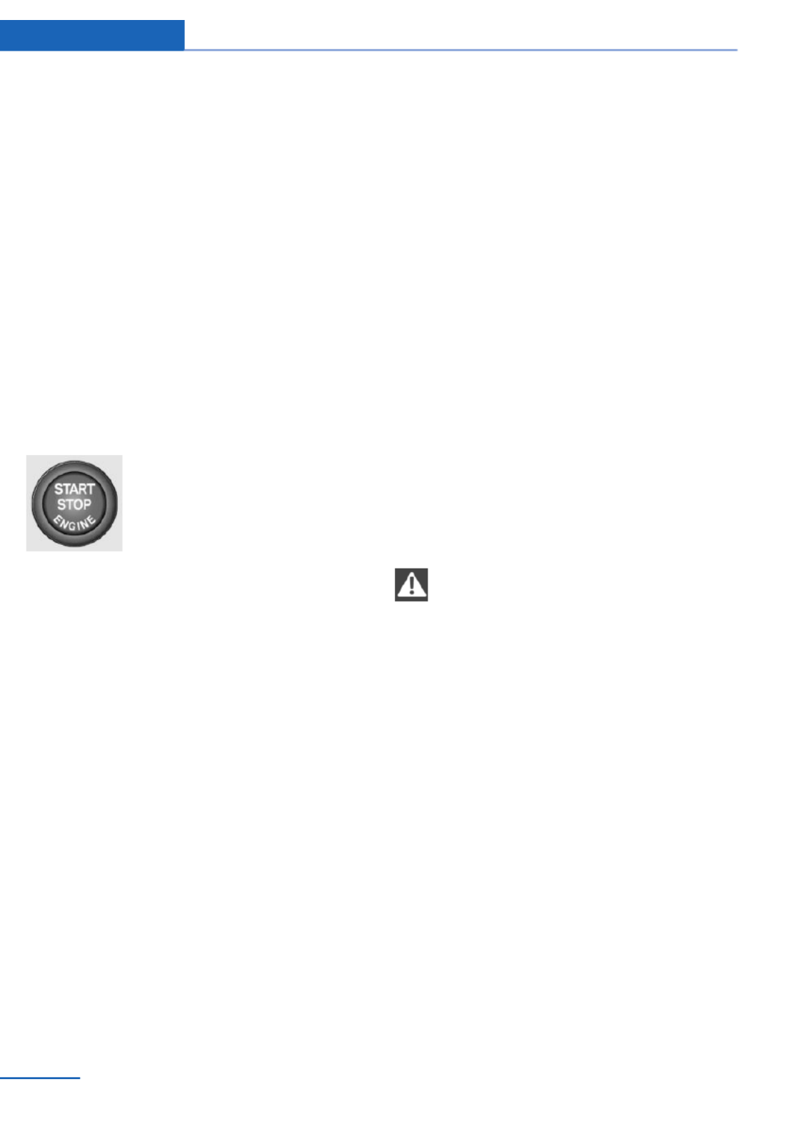
Driving
Vehicle equipment
All standard, country-specific and optional
equipment that is offered in the model series is
described in this chapter. Therefore, equip‐
ment is also described that is not available in a
vehicle, e. g., because of the selected optional
equipment or country variant. This also applies
for safety-related functions and systems.
Start/Stop button
The concept
Pressing the Start/Stop button
switches the ignition on or off
and starts the engine.
Automatic transmission: The
engine starts if the brake is de‐
pressed while pressing the Start/Stop button.
Manual transmission: the engine starts if the
clutch pedal is depressed when the Start/Stop
button is pressed.
Ignition on
Automatic transmission: Press the Start/Stop
button but do not depress the brake.
Manual-shift transmission: press the Start/
Stop button, and do not press on the clutch
pedal at the same time.
All vehicle systems are ready for operation.
Most of the indicator and warning lamps in the
instrument cluster light up for varying lengths
of time.
To save battery power when the engine is off,
switch off the ignition and any unnecessary
electronic systems/power consumers.
Note
If the engine is switched off and the ignition is
switched on, the system automatically
switches to the radio ready state when the
door is opened if the lights are switched off or
the daytime running lights are switched on.
Ignition off
Automatic transmission: Press the Start/Stop
button again, but do not depress the brake.
Manual-shift transmission: press the Start/
Stop button again, and do not press on the
clutch pedal at the same time.
All indicator lamps in the instrument cluster go
out.
To save battery power when the engine is off,
switch off the ignition and any unnecessary
electronic systems/power consumers.
P when the ignition is switched off
P is engaged automatically when the ig‐
nition is switched off. When in an automatic car
wash, for example, ensure that the ignition is
not switched off accidentally.◀
The ignition automatically cuts off while the
vehicle is stationary and the engine is stopped:
▷When locking the vehicle, and when the
low beams are activated.
▷Shortly before the battery is discharged
completely, so that the engine can still be
started. This function is only available
when the low beams are switched off.
▷When opening or closing the driver door, if
the driver's seat belt is unbuckled and the
low beams are switched off.
▷While the driver's seat belt is unbuckled, if
the driver's door is open and the low
beams are switched off.
When the ignition is switched off, by opening
or closing the driver's door or unbuckling the
Controls Driving
62 Online Edition for Part no. 01 40 2 925 793 - II/14

driver's seat belt, the radio ready state remains
active.
Radio ready state
Activate radio ready state:
▷When the engine is running: press the
Start/Stop button.
Some electronic systems/power consumers
remain ready for operation.
The radio ready state switches off automati‐
cally:
▷After approx. 8 minutes.
▷When the vehicle is locked using the cen‐
tral locking system.
▷Shortly before the battery is discharged
completely, so that the engine can still be
started.
Starting the engine
Hints
Enclosed areas
Do not let the engine run in enclosed
areas, since breathing in exhaust fumes may
lead to loss of consciousness and death. The
exhaust gases contain carbon monoxide, an
odorless and colorless, but highly toxic gas.◀
Unattended vehicle
Do not leave the vehicle unattended with
the engine running; doing so poses a risk of
danger.
Before leaving the vehicle with the engine run‐
ning, set the parking brake and place the trans‐
mission in selector lever position P or neutral
to prevent the vehicle from moving.◀
Repeated starting in quick succession
Avoid repeated unsuccessful attempts to
start the vehicle or starting the vehicle several
times in quick succession. Otherwise, the fuel
is not burned or is inadequately burned, posing
a risk of overheating and damage to the cata‐
lytic converter.◀
Do not wait for the engine to warm-up while
the vehicle remains stationary. Start driving at
moderate engine speeds.
Diesel engine
If the engine is cold and temperatures are be‐
low approx. 32 ℉/0 ℃, the start process may
be delayed somewhat due to automatic pre‐
heating.
A Check Control message is displayed.
Automatic transmission
Starting the engine
1. Depress the brake pedal.
2. Press the Start/Stop button.
The ignition is activated automatically for a
certain time and is stopped as soon as the en‐
gine starts.
Manual transmission
Starting the engine
1. Depress the brake pedal.
2. Press on the clutch pedal and shift to neu‐
tral.
3. Press the Start/Stop button.
The ignition is activated automatically for a
certain time and is stopped as soon as the en‐
gine starts.
Engine stop
Hints
Take the remote control with you
Take the remote control with you when
leaving the vehicle so that children, for exam‐
ple, cannot start the engine.◀
Driving Controls
63
Online Edition for Part no. 01 40 2 925 793 - II/14

Set the parking brake and further secure
the vehicle as required
Set the parking brake firmly when parking; oth‐
erwise, the vehicle could roll. On steep upward
and downward inclines, further secure the ve‐
hicle, for example, by turning the steering
wheel in the direction of the curb. ◀
Before driving into a car wash
In order for the vehicle to be able to roll into a
car wash, pay attention to the information re‐
garding Washing in automatic car washes, re‐
fer to page .225
Automatic transmission
Switching off the engine
1. Engage selector lever position P with the
vehicle stopped.
2. Press the Start/Stop button.
The engine is switched off.
The radio ready state is switched on.
3. Set the parking brake.
Manual transmission
Switching off the engine
1. With the vehicle at a standstill, press the
Start/Stop button.
2. Shift into first gear or reverse.
3. Set the parking brake.
Auto Start/Stop function
The concept
The Auto Start/Stop function helps save fuel.
The system switches off the engine during a
stop, e.g., in traffic congestion or at traffic
lights. The ignition remains switched on. The
engine starts again automatically for driving
off.
Automatic mode
After every start of the engine using the Start/
Stop button, the Auto Start/Stop function is in
the last selected state, refer to page .65
When the Auto Start Stop function is active, it
is available when the vehicle is traveling faster
than about 3 mph, approx. 5 km/h.
Engine stop
The engine is switched off automatically dur‐
ing a stop under the following conditions:
Automatic transmission:
▷The selector lever is in selector lever posi‐
tion D.
▷Brake pedal remains depressed while the
vehicle is stopped.
▷The driver's safety belt is buckled or the
driver's door is closed.
Manual transmission:
▷Neutral is engaged and the clutch pedal is
not pressed.
▷The driver's safety belt is buckled or the
driver's door is closed.
The air flow of the air conditioner is reduced
when the engine is switched off.
Displays in the instrument cluster
The READY display in the tach‐
ometer signals that the Auto
Start/Stop function is ready to
start the engine automatically.
The display indicates that the
conditions for an automatic en‐
gine stop have not been satis‐
fied.
Note
The engine is not switched off automatically in
the following situations:
▷External temperature too low.
Controls Driving
64 Online Edition for Part no. 01 40 2 925 793 - II/14
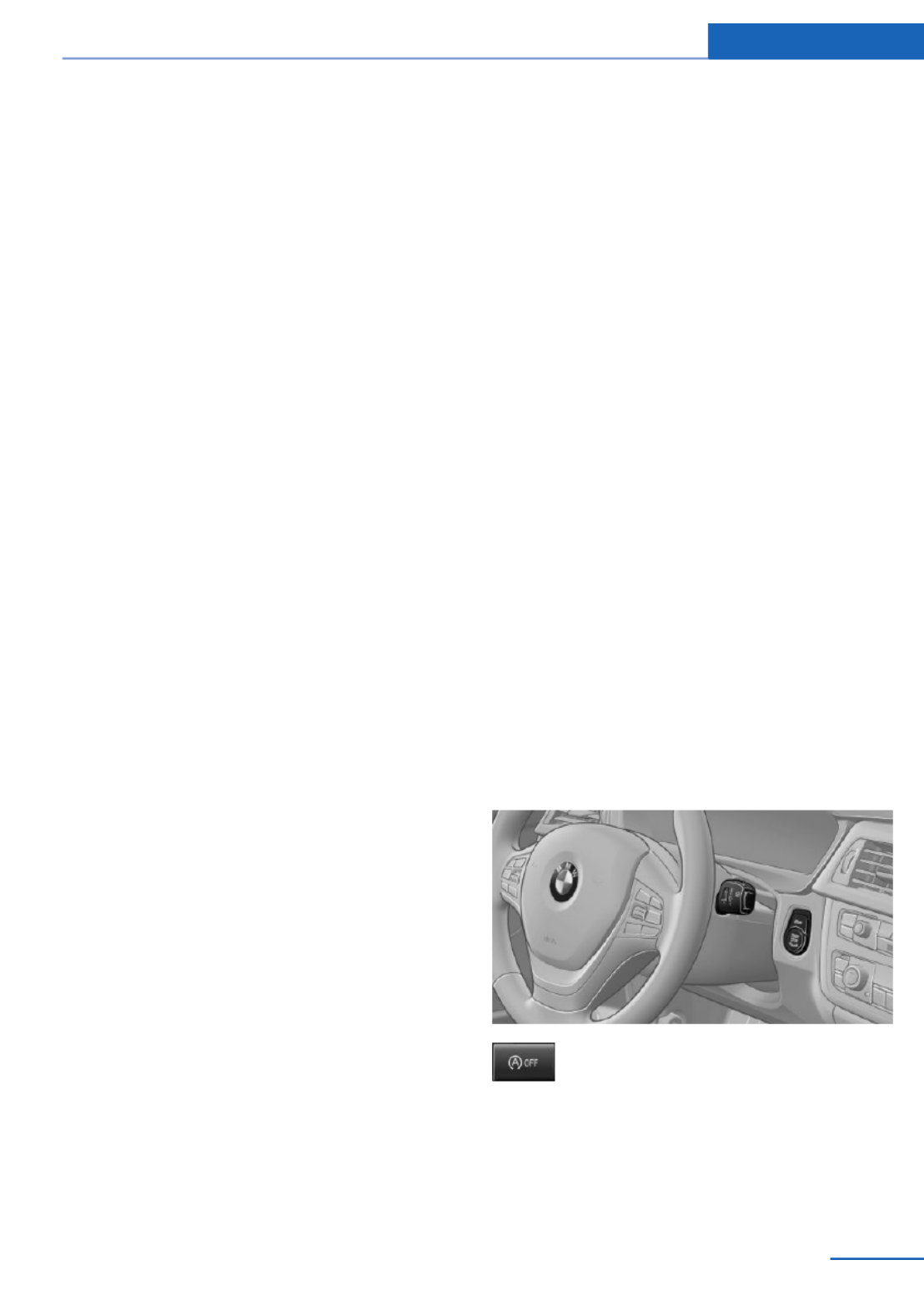
▷The external temperature is high and auto‐
matic climate control is running.
▷The passenger compartment has not yet
been heated or cooled to the required
level.
▷The engine is not yet at operating temper‐
ature.
▷The wheels are at a sharp angle or the
steering wheel is being turned.
▷After driving in reverse.
▷Fogging of the windows when the auto‐
matic climate control is switched on.
▷Vehicle battery is heavily discharged.
▷The engine compartment lid is unlocked.
▷The parking assistant is activated.
▷Stop-and-go traffic.
▷The selector lever is in position N or M/S.
▷Use of fuel with high ethanol content.
Starting the engine
The engine starts automatically under the fol‐
lowing conditions:
▷Automatic transmission:
By releasing the brake pedal.
▷Manual transmission:
The clutch pedal is pressed.
After the engine starts, accelerate as usual.
Safety mode
After the engine switches off automatically, it
will not start again automatically if any one of
the following conditions are met.
▷The driver's safety belt is unbuckled and
the driver's door is open.
▷The hood was unlocked.
Some indicator lamps light up for varying
lengths of time.
The engine can only be started via the Start/
Stop button.
Note
Even if driving away was not intended, the de‐
activated engine starts up automatically in the
following situations:
▷Excessive warming of the passenger com‐
partment when the cooling function is
switched on.
▷The steering wheel is turned.
▷Automatic transmission: change from se‐
lector lever position D to N, R or M/S.
▷Automatic transmission: change from se‐
lector lever position P to N, D, R or M/S.
▷The vehicle begins rolling.
▷Fogging of the windows when the auto‐
matic climate control is switched on.
▷Vehicle battery is heavily discharged.
▷Excessive cooling of the passenger com‐
partment when the heating is switched on.
▷Low brake vacuum pressure; this can oc‐
cur, for example, if the brake pedal is de‐
pressed a number of times in succession.
Activating/deactivating the system
manually
Using the button
Press the button.
▷LED comes on: Auto Start Stop function is
deactivated.
The engine is started during an automatic
engine stop.
Driving Controls
65
Online Edition for Part no. 01 40 2 925 793 - II/14

The engine can only be stopped or started
via the Start/Stop button.
▷LED goes out: Auto Start Stop function is
activated.
Switching off the vehicle during an
automatic engine stop
During an automatic engine stop, the vehicle
can be switched off permanently, e.g., when
leaving it.
1. Press the Start/Stop button. The ignition is
switched off. The Auto Start/Stop function
is deactivated.
Selector lever position P is engaged auto‐
matically.
2. Set the parking brake.
Engine start as usual via Start/Stop button.
Automatic deactivation
In certain situations, the Auto Start/Stop func‐
tion is deactivated automatically for safety rea‐
sons, such as when the driver is detected to be
absent.
Malfunction
The Auto Start/Stop function no longer
switches of the engine automatically. A Check
Control message is displayed. It is possible to
continue driving. Have the system checked.
Parking brake
Applying
The lever automatically engages after being
pulled up.
The indicator lamp lights up red. The
parking brake is set.
Lower lamp: indicator lamp in Canadian
models
Releasing
Raise lever slightly, press the button and guide
the lever down.
Hints
Use while driving
If on a rare occasion it is necessary to
use the parking brake while driving, do not use
excessive force when applying it. When using
it, keep the button on the lever depressed.
Otherwise, using excessive force when apply‐
ing the parking brake may cause the rear
wheels to lock, resulting in fishtailing.◀
To prevent corrosion and braking control on
one side only, lightly apply the parking brake
periodically while coasting, if traffic conditions
permit.
The brake lamps will not light up if the parking
brake is engaged.
Turn signal, high beams,
headlamp flasher
Turn signal
Do not fold in the exterior mirrors
Do not fold in the exterior mirror while
driving and when the turn signals/warning
flashers are working, or else the additional
flasher lights in the exterior mirror will no lon‐
ger be in the prescribed position and will be
difficult to see.◀
Controls Driving
66 Online Edition for Part no. 01 40 2 925 793 - II/14

Switching on
Press the wiper levers up.
The lever automatically returns to its initial po‐
sition when released.
▷Normal wiping speed: press up once.
The wipers switch to intermittent operation
when the vehicle is stationary.
▷Fast wiping speed: press up twice or press
once beyond the resistance point.
The wipers switch to normal speed when
the vehicle is stationary.
Switching off and brief wipe
Press the wiper levers down.
The lever automatically returns to its initial po‐
sition when released.
▷Brief wipe: press down once.
▷To switch off normal wipe: press down
once.
▷To switch off fast wipe: press down twice.
Intermittent operation or rain sensor
The concept
Without the rain sensor, the frequency of the
wiper operation is preset.
The rain sensor automatically controls the time
between wipes depending on the intensity of
the rainfall. The sensor is located on the wind‐
shield, directly behind the interior rearview mir‐
ror.
Activating/deactivating
Press the button on the wiper lever.
The LED in the wiper lever lights up and a wip‐
ing operation is started. If there is frost, wiper
operation is not started.
Deactivate the rain sensor in car washes
Deactivate the rain sensor when passing
through an automatic car wash; otherwise,
damage could be caused by undesired wiper
activation.◀
Controls Driving
68 Online Edition for Part no. 01 40 2 925 793 - II/14

Setting the frequency or sensitivity of
the rain sensor
Turn the thumbwheel.
Clean the windshield, headlamps
Pull the wiper lever.
The system sprays washer fluid on the wind‐
shield and activates the wipers briefly.
In addition, the headlamps are cleaned at regu‐
lar intervals when the vehicle lights are
switched on.
Do not use the washer system at freezing
temperatures
Do not use the washers if there is any danger
that the fluid will freeze on the windshield; oth‐
erwise, your vision could be obscured. For this
reason, use antifreeze.
Avoid using the washer when the reservoir is
empty; otherwise, you could damage the
pump.◀
Windshield washer nozzles
The windshield washer nozzles are automati‐
cally heated while the ignition is switched on.
Switching on the rear window wiper
Press the wiper lever forward: intermittent
wipe. When reverse gear is engaged, the sys‐
tem switches to continuous operation.
To clean the rear window, press the wiper lever
further forward.
Fold-out position of the wipers
Required when changing the wiper blades or
under frosty conditions, for example.
1. Switch the ignition on and off again.
2. Under frosty conditions, ensure that the
wiper blades are not frozen onto the wind‐
shield.
3. Press the wiper lever up beyond the point
of resistance and hold it for approx. 3 sec‐
onds, until the wiper remains in a nearly
vertical position.
After the wipers are folded back down, the
wiper system must be reactivated.
Fold the wipers back down
Before switching the ignition on, fold the
wipers back down to the windshield; other‐
wise, the wipers may become damaged when
they are switched on.◀
1. Switch on the ignition.
2. Press the wiper levers down. The wipers
move to their resting position and are
ready for operation.
Driving Controls
69
Online Edition for Part no. 01 40 2 925 793 - II/14

N is Neutral
Use in automatic car washes, for example. The
vehicle can roll.
When the ignition is switched off, refer to
page , selector lever position P is engaged62
automatically.
P Park
Select only when the vehicle is stationary. The
drive wheels are blocked.
P is engaged automatically:
▷After the engine is switched off when the
vehicle is in radio ready state, refer to
page , or when the ignition is switched63
off, refer to page , and when position R62
or D is engaged.
▷With the ignition off, if selector lever posi‐
tion N is engaged.
▷If the safety belt is unbuckled, the driver's
door is opened, and the brake pedal is not
pressed while the vehicle is stationary and
position D or R is engaged.
Before exiting the vehicle, make sure that se‐
lector lever position P of the automatic trans‐
mission is engaged. Otherwise, the vehicle
may begin to roll.
Kickdown
Kickdown is used to achieve maximum driving
performance. Press on the accelerator pedal
beyond the resistance point at the full throttle
position.
Engaging selector lever positions
▷It is not possible to shift out of selector
lever position P until the engine is running
and the brake is applied.
▷With the vehicle stationary, press on the
brake pedal before shifting out of P or N;
otherwise, the shift command will not be
executed: shift lock.
Press on the brake pedal until you
start driving
To prevent the vehicle from creeping after
you select a gear, maintain pressure on the
brake pedal until you are ready to start.◀
Engaging D, R and N
Briefly push the selector lever in the desired di‐
rection, beyond a resistance point if necessary.
After releasing the selector lever, it returns to
its center position.
Press unlock button, in order to:
▷Engage R.
▷Shift out of P.
Driving Controls
71
Online Edition for Part no. 01 40 2 925 793 - II/14

Engaging P
Press button P.
Sport program and manual mode
Activating the sport program
Press the selector lever to the left out of selec‐
tor lever position D.
The sport program of the transmission is acti‐
vated.
Activating the M/S manual mode
1. Press the selector lever to the left out of
selector lever position D.
2. Push the selector lever forward or pull it
backward.
Manual mode becomes active and the gear is
changed.
The engaged gear is displayed in the instru‐
ment cluster, e.g., M1.
Once maximum engine speed is attained, M/S
manual mode is automatically upshifted as
needed.
Switching to manual mode
▷To shift down: press the selector lever for‐
ward.
▷To shift up: pull the selector lever rear‐
wards.
Gears will only be shifted at appropriate engine
and road speeds, e.g., downshifting is not pos‐
sible if the engine speed is too high.
The selected gear is briefly displayed in the in‐
strument cluster, followed by the current gear.
Sport automatic transmission: prevent
automatic upshifting in M/S manual
mode
For vehicles with Sport automatic transmis‐
sions, automatic shift operations are not per‐
formed, at maximum engine speed for exam‐
ple, if one of the following conditions is met:
▷DSC deactivated.
▷TRACTION activated.
▷SPORT+ activated.
In addition, the kickdown is deactivated.
Ending the sport program/manual
mode
Push the selector lever to the right.
D is displayed in the instrument cluster.
Shift paddles
The shift paddles on the steering wheel allow
you to shift gears quickly while keeping both
hands on the steering wheel.
Controls Driving
72 Online Edition for Part no. 01 40 2 925 793 - II/14

If the shift paddles on the steering wheel are
used to shift gears in automatic mode, the
transmission temporarily switches to manual
mode.
If the shift paddles are not used and the vehicle
is not accelerated for a certain time, the sys‐
tem switches back into automatic mode if the
selector lever is in selector lever position D.
▷Shift up: pull right shift paddle.
▷Shift down: pull left shift paddle.
Gears will only be shifted at appropriate engine
and road speeds, for example downshifting is
not possible if the engine speed is too high.
The selected gear is briefly displayed in the in‐
strument cluster, followed by the current gear.
Displays in the instrument cluster
The selector lever position is dis‐
played, e.g.: P.
Sport automatic transmission: Launch
Control
The concept
Launch Control enables optimum acceleration
on surfaces with good traction.
Hints
Component wear
Do not use Launch Control too often;
otherwise, this may result in premature wear of
components due to the high stress placed on
the vehicle.◀
Did not use Launch Control during the break-
in, refer to page , period.168
To increase vehicle stability, activate DSC
again as soon as possible.
An experienced driver may be able to achieve
better acceleration values in DSC OFF mode.
Requirements
Launch Control is available when the engine is
warmed up, that is, after uninterrupted driving
of at least 6 miles/10 km.
To start with Launch Control do not steer the
steering wheel.
Start with launch control
While the engine is running:
1. Press button or select with the
Driving Dynamics Control Sport+.
TRACTION is displayed in the instrument
cluster and the indicator lamp for DSC OFF
lights up.
2. Engage gear S.
3. With the left foot, forcefully press down on
the brake.
4. Press and hold down the accelerator pedal
beyond the resistance point at the full
throttle position.
A flag symbol appears in the instrument
cluster.
5. The starting engine speed adjusts. Within
3 seconds, release the brake.
Before using Launch Control, allow the trans‐
mission to cool down for approx. 5 minutes.
Launch Control adjusts to the surrounding
conditions, e.g., wet pavement, when used
again.
Driving Controls
73
Online Edition for Part no. 01 40 2 925 793 - II/14

Displays
Vehicle equipment
All standard, country-specific and optional
equipment that is offered in the model series is
described in this chapter. Therefore, equip‐
ment is also described that is not available in a
vehicle, e. g., because of the selected optional
equipment or country variant. This also applies
for safety-related functions and systems.
Instrument cluster
Overview, instrument cluster
1Fuel gauge 79
2Speedometer
3Indicator/warning lamps 77
4Tachometer 79
5Engine oil temperature 79
6Current fuel consumption 81
7Electronic displays 76
8Display/reset miles 80
Controls Displays
74 Online Edition for Part no. 01 40 2 925 793 - II/14
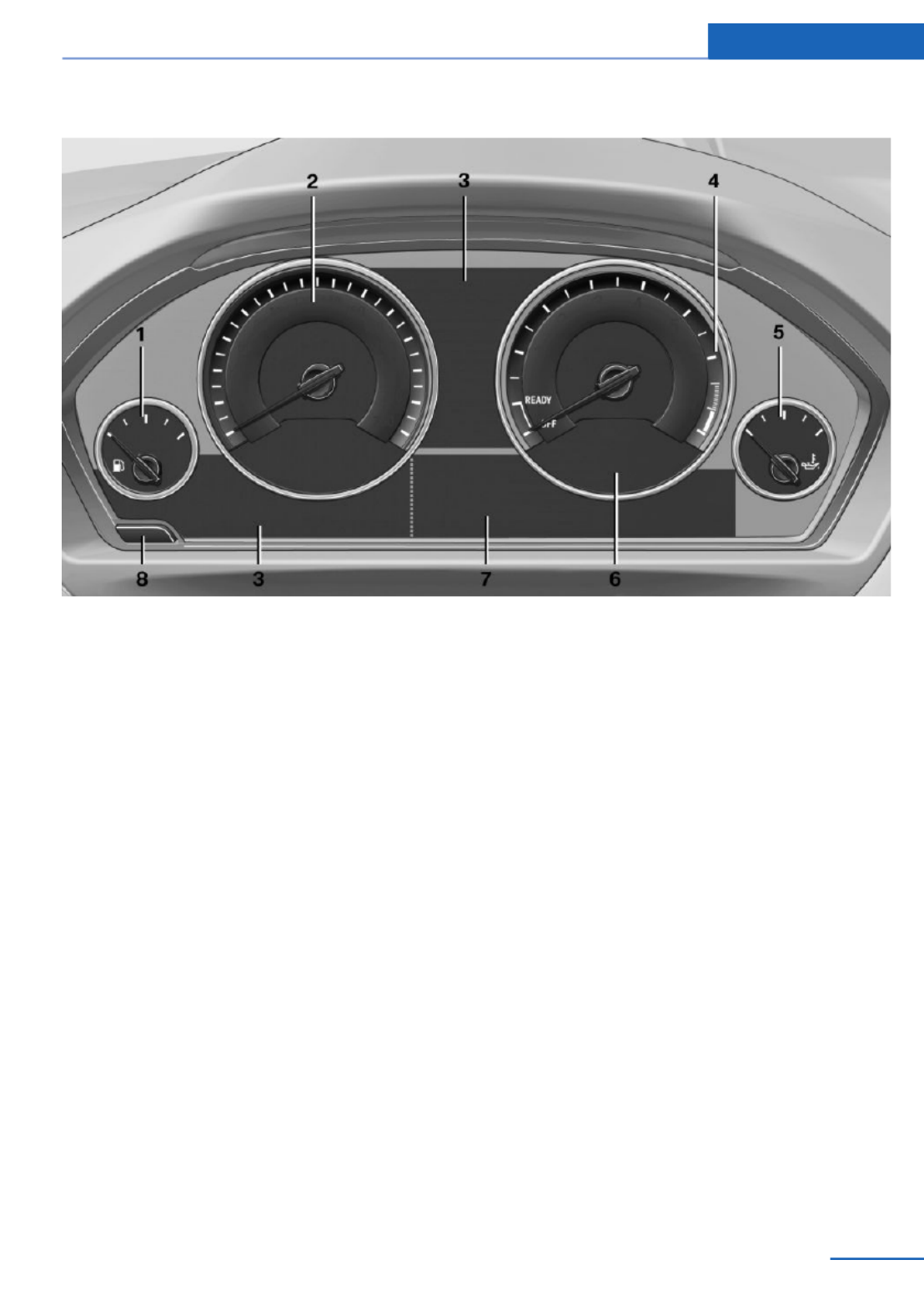
Overview, instrument cluster with enhanced features
1 Fuel gauge 79
2 Speedometer
3 Indicator/warning lamps 77
4 Tachometer 79
5 Engine oil temperature 79
6 Current fuel consumption 81
7 Electronic displays 76
8 Display/reset miles 80
Displays Controls
75
Online Edition for Part no. 01 40 2 925 793 - II/14
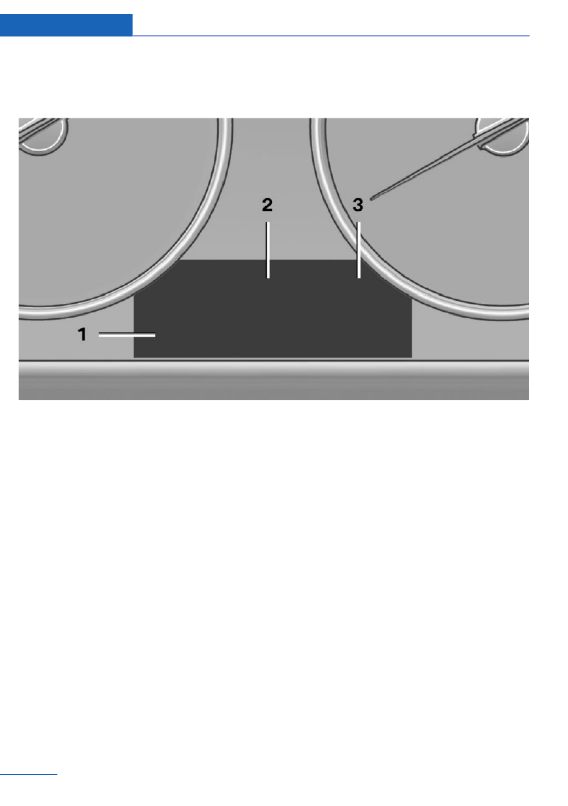
Electronic displays
Overview, instrument cluster
1 Messages, e.g., Check Control 77
Time 80
Date 80
External temperature 80
Selection lists 84
Service requirements 81
Miles/trip miles 80
Computer 84
2 Transmission display 73
Gear shift indicator 82
3 Status, Driving Dynamics Control 117
Controls Displays
76 Online Edition for Part no. 01 40 2 925 793 - II/14

Overview, instrument cluster with enhanced features
1 Time 80
External temperature 80
Date 80
Selection list, such as for the radio 84
Speed limit detection 82
Computer 84
Miles/trip miles 80
Navigation display, see user's manual for
Navigation, Entertainment and Communi‐
cation.
Status, Driving Dynamics Control 117
2 Energy recovery 81
Transmission display 73
Current fuel consumption 81
ECO PRO 175
3 Messages, e.g., Check Control 77
Service requirements 81
Check Control
The concept
The Check Control system monitors functions
in the vehicle and notifies you of malfunctions
in the monitored systems.
A Check Control message is displayed as a
combination of indicator or warning lamps and
text messages in the instrument cluster and in
the Head-up Display.
In addition, an acoustic signal may be output
and a text message may appear on the Control
Display.
Indicator/warning lamps
The indicator and warning lamps in the instru‐
ment cluster can light up in a variety of combi‐
nations and colors.
Several of the lamps are checked for proper
functioning and light up temporarily when the
engine is started or the ignition is switched on.
Displays Controls
77
Online Edition for Part no. 01 40 2 925 793 - II/14

Overview: indicator/warning lamps
Symbol Function or system
Turn signal.
Front fog lamps.
High beams.
High-beam Assistant.
Parking lamps, headlamp control.
Active Cruise Control.
Vehicle detection, Active Cruise
Control: collision warning.
Pedestrian warning.
Cruise control.
Lane departure warning.
DSC Dynamic Stability Control.
DSC Dynamic Stability Control is
deactivated or DTC Dynamic Trac‐
tion Control is activated.
Tire Pressure Monitor.
Flat Tire Monitor.
Safety belts.
Symbol Function or system
Airbag system.
Steering system.
Engine functions.
Parking brake.
Brake system.
In Canadian models
Parking brake.
Brake system.
ABS Antilock Brake System.
In Canadian models
ABS Antilock Brake System.
At least one Check Control mes‐
sage is displayed or is stored (sym‐
bol in display).
Text messages
Text messages in combination with a symbol
in the instrument cluster explain a Check Con‐
trol message and the meaning of the indicator
and warning lamps.
Supplementary text messages
Additional information, such as on the cause of
a fault or the required action, can be called up
via Check Control.
The supplementary text of urgent messages is
automatically displayed on the Control Display.
Symbols
Depending on the Check Control message, the
following functions can be selected.
Controls Displays
78 Online Edition for Part no. 01 40 2 925 793 - II/14
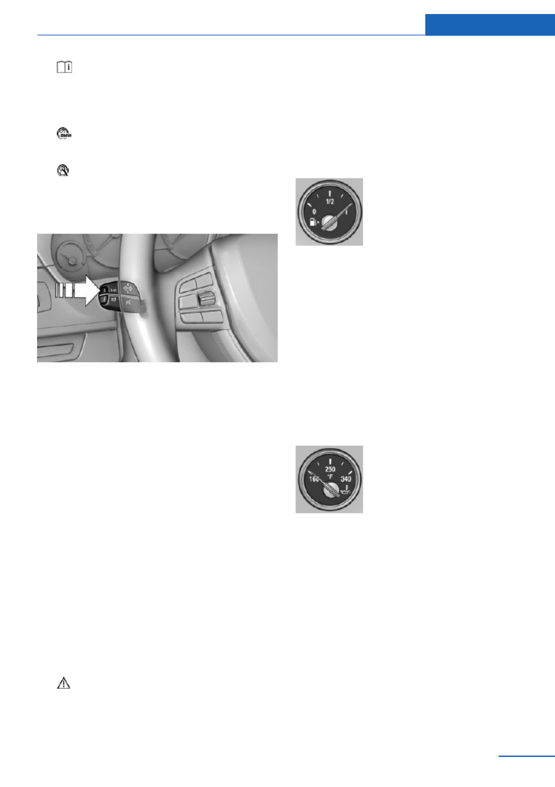
▷ "Owner's Manual"
Display additional information about the
Check Control message in the Integrated
Owner's Manual.
▷ "Service request"
Contact your service center.
▷ "Roadside Assistance"
Contact Roadside Assistance.
Hiding Check Control messages
Press the onboard computer button on the
turn signal lever.
▷Some Check Control messages are dis‐
played continuously and are not cleared
until the malfunction is eliminated. If sev‐
eral malfunctions occur at once, the mes‐
sages are displayed consecutively.
These messages can be hidden for approx.
8 seconds. After this time, they are dis‐
played again automatically.
▷Other Check Control messages are hidden
automatically after approx. 20 seconds.
They are stored and can be displayed
again later.
Displaying stored Check Control
messages
1. "Vehicle Info"
2. "Vehicle status"
3. "Check Control"
4. Select the text message.
Messages after trip completion
Special messages that are displayed during
driving are displayed again after the ignition is
switched off.
Fuel gauge
The vehicle inclination may
cause the display to vary.
US models: the arrow beside the
fuel pump symbol shows which
side of the vehicle the fuel filler
flap is on.
Hints on refueling, refer to page .184
Tachometer
Always avoid engine speeds in the red warning
field. In this range, the fuel supply is inter‐
rupted to protect the engine.
Engine oil temperature
▷Cold engine: the pointer is at
the low temperature end.
Drive at moderate engine
and vehicle speeds.
▷Normal operating tempera‐
ture: the pointer is in the
middle or in the left half of
the temperature display.
▷Hot engine: the pointer is at the high end of
the temperature range. A Check Control
message is also displayed.
Coolant temperature
If the coolant along with the engine becomes
too hot, a Check Control message is displayed.
Check the coolant level, refer to page .204
Displays Controls
79
Online Edition for Part no. 01 40 2 925 793 - II/14

Odometer and trip odometer
Display
▷Odometer, arrow 1.
▷Trip odometer, arrow 2.
Show/reset kilometers
Press the knob.
▷When the ignition is
switched off, the time, the
external temperature and
the odometer are displayed.
▷When the ignition is switched on, the trip
odometer is reset.
External temperature
If the indicator drops to
+37 ℉/+3 ℃ or lower, a signal
sounds.
A Check Control message is
displayed.
There is an increased risk of ice on roads.
Ice on roads
Even at temperatures above
+37 ℉/+3 ℃, there can be a risk of ice on
roads.
Therefore, drive carefully on bridges and
shaded roads, for example, to avoid the in‐
creased risk of an accident.◀
Time
The time is displayed at the bot‐
tom of the instrument cluster.
Setting the time and time for‐
mat, refer to page .87
Date
The date is displayed in the
computer.
Setting the date and date for‐
mat, refer to page .87
Range
Display
After the reserve range is
reached:
▷A Check Control message is
displayed briefly.
▷The remaining range is
shown on the onboard com‐
puter.
▷When a dynamic driving style is used, such
as when cornering quickly, operation of the
engine is not always ensured.
The Check Control message appears continu‐
ously below a range of approx. 30 miles/50 km.
Refuel promptly
Refuel no later than at a range of
30 miles/50 km, or operation of the engine is
not ensured and damage may occur.◀
Displaying the cruising range
Depending on the equipment version, the
range is displayed in the instrument cluster.
1. "Settings"
2. "Instr. cluster display"
3. "Additional indicators"
Controls Displays
80 Online Edition for Part no. 01 40 2 925 793 - II/14
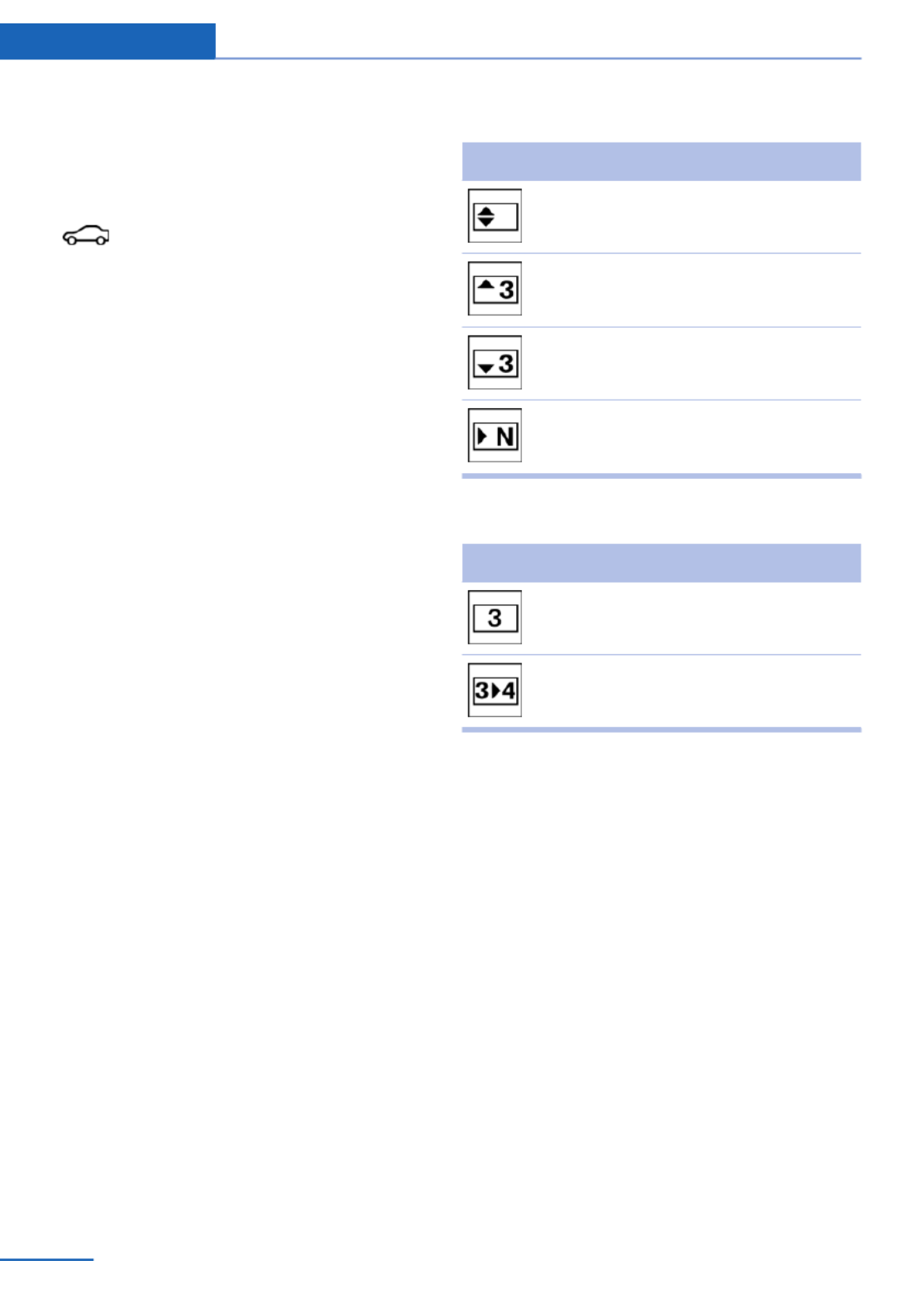
Ensure that the vehicle date and time are set
correctly.
1. "Vehicle Info"
2. "Vehicle status"
3. "Service required"
4. "§ Vehicle inspection"
5. "Date:"
6. Adjust the settings.
7. Confirm.
The entered date is stored.
Automatic Service Request
Data regarding the service status or legally
mandated inspections of the vehicle are auto‐
matically transmitted to your service center
before a service due date.
You can check when your service center was
notified.
1. "Vehicle Info"
2. "Vehicle status"
3. Open "Options".
4. "Last Service Request"
Gear shift indicator
The concept
The system recommends the most fuel effi‐
cient gear for the current driving situation.
Depending on how the vehicle is equipped and
the country-specific version of the vehicle, the
gear shift indicator is active in the manual
mode of the automatic transmission and in the
manual transmission.
Indicators to shift up or down are displayed in
the instrument cluster.
On vehicles without a gear shift indicator, the
engaged gear is displayed.
Manual transmission: displays
Symbol Description
Fuel efficient gear is engaged.
Shift up to fuel efficient gear.
Shift down to fuel efficient gear.
Shift into neutral.
Automatic transmission: displays
Example Description
Fuel efficient gear is engaged.
Shift into fuel efficient gear.
Speed limit detection with
No Passing Information
The concept
Speed limit detection
Speed limit detection uses a symbol in the
shape of a traffic sign to display the currently
detected speed limit. The camera at the base
of the interior rearview mirror detects traffic
signs at the edge of the road as well as variable
overhead sign posts. Traffic signs with extra
symbols for wet road conditions, etc. are also
detected and compared with vehicle interior
data, such as for the rain sensor, and are dis‐
played depending on the situation. The system
takes into account the information stored in
Controls Displays
82 Online Edition for Part no. 01 40 2 925 793 - II/14

the navigation system and also displays speed
limits present on routes without signs.
No Passing Information
No Passing Information in the instrument clus‐
ter displays the beginnings and ends of no
passing zones detected by the camera. The
system accounts for only the beginnings and
ends of No Passing zones marked by signs.
No display is shown:
▷In countries where No Passing zones are
primarily identified with road markings.
▷On routes without signage.
▷Where there are railroad crossings, high‐
way markings or other situations where no
signage is present, but passing would not
be permitted.
Hints
Personal judgment
The system cannot serve as a substitute
for the driver's personal judgment of the traffic
situation.
The system assists the driver and does not re‐
place the human eye.◀
At a glance
Camera
The camera is located near the base of the
mirror.
Keep the windshield in the area behind the in‐
terior rear view mirror clean and clear.
Switching on/off
1. "Settings"
2. "Instr. cluster display"
3. "Speed limit information"
If speed limit detection is switched on, it can
be displayed on the info display in the instru‐
ment cluster via the onboard computer.
No Passing Information is displayed together
with the activated speed limit information.
Display
The following is displayed in the instrument
cluster.
Speed limit detection
Current speed limit.
Speed limit detection is not
available.
Speed limit detection can also be displayed in
the Head-up Display.
No Passing Information
▷Start of No Passing zone.
▷End of No Passing zone.
▷No Passing Information not
available.
No Passing Information can also be displayed
in the Head-up Display.
System limits
The system may not be fully functional and
may provide incorrect information in the fol‐
lowing situations:
▷In heavy fog, rain or snowfall.
Displays Controls
83
Online Edition for Part no. 01 40 2 925 793 - II/14

▷When signs are concealed by objects.
▷When driving very close to the vehicle in
front of you.
▷When driving toward bright lights.
▷When the windshield behind the interior
rearview mirror is fogged over, dirty or cov‐
ered by a sticker, etc.
▷In the event of incorrect detection by the
camera.
▷If the speed limits stored in the navigation
system are incorrect.
▷In areas not covered by the navigation sys‐
tem.
▷When roads differ from the navigation,
such as due to changes in the road net‐
work.
▷When passing buses or trucks with a
speed sticker.
▷If the traffic signs are non-conforming.
▷During calibration of the camera immedi‐
ately after vehicle shipment.
Selection lists in the
instrument cluster
The concept
Depending on the equipment version, the fol‐
lowing can be displayed or operated using the
buttons and the thumbwheel on the steering
wheel and the displays in the instrument clus‐
ter and the Head-up Display:
▷Current audio source.
▷Redial on telephone.
▷Activation of the voice activation system.
In addition, programs of the Driving Dynamics
Control are displayed.
Display
Depending on the equipment version, the list
in the instrument cluster can differ from the il‐
lustration.
Activating a list and adjusting the
setting
On the right side of the steering wheel, turn
the thumbwheel to activate the corresponding
list.
Using the thumbwheel, select the desired set‐
ting and confirm it by pressing the thumb‐
wheel.
Computer
Indication in the info display
The information from the on‐
board computer is shown in the
info display in the instrument
cluster.
Controls Displays
84 Online Edition for Part no. 01 40 2 925 793 - II/14

Calling up information on the info
display
Press the onboard computer button on the
turn signal lever.
Information is displayed on the info display of
the instrument cluster.
Information at a glance
Repeatedly pressing the button on the turn
signal lever calls up the following information
on the info display:
▷Range.
▷Average fuel consumption.
▷Current fuel consumption.
▷Average speed.
▷Date.
▷Speed limit detection.
▷Time of arrival.
When destination guidance is activated in
the navigation system.
▷Distance to destination.
When destination guidance is activated in
the navigation system.
▷Arrow view of navigation system.
When destination guidance is activated in
the navigation system.
When the arrow view in the Head-up Dis‐
play is inactive.
▷ECO PRO bonus range.
Adjusting the info display
You can select what information from the on‐
board computer is to be displayed on the info
display of the instrument cluster.
1. "Settings"
2. "Instr. cluster display"
3. Select the desired displays.
Information in detail
Range
Displays the estimated cruising range available
with the remaining fuel.
It is calculated based on your driving style over
the last 20 miles/30 km.
If there is only enough fuel left for less than
45 miles/80 km, the color of the display
changes.
Average fuel consumption
The average fuel consumption is calculated for
the period during which the engine is running.
The average fuel consumption is calculated for
the distance traveled since the last reset by the
onboard computer.
Average speed
Periods in which the vehicle is parked with the
engine manually stopped do not enter into the
calculation of the average speed.
Resetting average values
Press and hold the computer button on the
turn signal lever.
Distance to destination
The distance remaining to the destination is
displayed if a destination is entered in the navi‐
gation system before the trip is started.
The distance to the destination is adopted au‐
tomatically.
Displays Controls
85
Online Edition for Part no. 01 40 2 925 793 - II/14

Time of arrival
The estimated time of arrival is
displayed if a destination is en‐
tered in the navigation system
before the trip is started.
The time must be correctly set.
Speed limit detection
Description of the speed limit detection, refer
to page , function.82
Trip computer
The vehicle features two types of computer.
▷"Onboard info": the values can be reset as
often as necessary.
▷"Trip computer": the values provide an
overview of the current trip.
Resetting the trip computer
1. "Vehicle Info"
2. "Trip computer"
3. "Reset": all values are reset.
"Automatically reset": all values are reset
approx. 4 hours after the vehicle comes to
a standstill.
Display on the Control Display
Display the onboard computer or trip computer
on the Control Display.
1. "Vehicle Info"
2. "Onboard info" or "Trip computer"
Resetting the fuel consumption or
speed
1. "Vehicle Info"
2. "Onboard info"
3. "Consumpt." or "Speed"
4. "Yes"
Sport displays
The concept
In the Control Display, the current values for
power and torque can be displayed.
Displaying sport displays in the
Control Display
1. "Vehicle Info"
2. "Sport displays"
Speed warning
The concept
Display of a speed limit which, when reached,
should cause a warning to be issued.
The warning is repeated if the vehicle speed
drops below the set speed limit once by at
least 3 mph/5 km/h.
Displaying, setting or changing the
limit
1. "Settings"
2. "Speed"
3. "Warning at:"
4. Turn the controller until the desired limit is
displayed.
5. Press the controller.
The speed limit is stored.
Activating/deactivating the limit
1. "Settings"
2. "Speed"
3. "Warning"
4. Press the controller.
Setting your current speed as the limit
1. "Settings"
2. "Speed"
Controls Displays
86 Online Edition for Part no. 01 40 2 925 793 - II/14

3. "Select current speed"
4. Press the controller.
The current vehicle speed is stored as the
limit.
Settings on the Control
Display
Time
Setting the time zone
1. "Settings"
2. "Time/Date"
3. "Time zone"
4. Select the desired time zone.
The time zone is stored.
Setting the time
1. "Settings"
2. "Time/Date"
3. "Time:"
4. Turn the controller until the desired hours
are displayed.
5. Press the controller.
6. Turn the controller until the desired mi‐
nutes are displayed.
7. Press the controller.
The time is stored.
Setting the time format
1. "Settings"
2. "Time/Date"
3. "Format:"
4. Select the desired format.
The time format is stored.
Automatic time setting
Depending on the equipment version, the time,
date and, if necessary, the time zone are up‐
dated automatically.
1. "Settings"
2. "Time/Date"
3. "Auto time set"
Date
Setting the date
1. "Settings"
2. "Time/Date"
3. "Date:"
4. Turn the controller until the desired day is
displayed.
5. Press the controller.
6. Make the necessary settings for the month
and year.
The date is stored.
Setting the date format
1. "Settings"
2. "Time/Date"
3. "Format:"
4. Select the desired format.
The date format is stored.
Language
Setting the language
To set the language on the Control Display:
1. "Settings"
2. "Language/Units"
3. "Language:"
4. Select the desired language.
The setting is stored for the remote control
currently in use.
Displays Controls
87
Online Edition for Part no. 01 40 2 925 793 - II/14

Setting the voice dialog
Voice dialog for the voice activation system,
refer to page .25
Units of measure
Setting the units of measure
To set the units for fuel consumption, route/
distance and temperature:
1. "Settings"
2. "Language/Units"
3. Select the desired menu item.
4. Select the desired unit.
The setting is stored for the remote control
currently in use.
Brightness
Setting the brightness
To set the brightness of the Control Display:
1. "Settings"
2. "Control display"
3. "Brightness"
4. Turn the controller until the desired bright‐
ness is set.
5. Press the controller.
The setting is stored for the remote control
currently in use.
Depending on the light conditions, the bright‐
ness control may not be clearly visible.
Assist system information
Display on the Control Display
Information on the Assist system can be dis‐
played by activating Assist on the Control Dis‐
play.
1. "Settings"
2. "Control display"
3. "Driver assistance info"
Head-up Display
The concept
This system projects important information
into the driver's field of vision, e.g., the speed.
The driver can get information without averting
his or her eyes from the road.
Display visibility
The visibility of the displays in the Head-up
Display is influenced by the following factors:
▷Certain sitting positions.
▷Objects on the cover of the Head-up Dis‐
play.
▷Sunglasses with certain polarization filters.
▷Wet roads.
▷Unfavorable light conditions.
If the image is distorted, check the basic set‐
tings.
Switching on/off
1. "Settings"
2. "Head-Up Display"
3. "Head-Up Display"
Display
Overview
▷Speed.
▷Navigation system.
▷Check Control messages.
▷Selection list from the instrument cluster.
Controls Displays
88 Online Edition for Part no. 01 40 2 925 793 - II/14

▷Driver assistance systems.
Some of this information is only displayed
briefly as needed.
Selecting displays in the Head-up
Display
1. "Settings"
2. "Head-Up Display"
3. "Displayed information"
4. Select the desired displays in the Head-up
Display.
The settings are stored for the remote control
currently in use.
Setting the brightness
The brightness is automatically adjusted to the
ambient light.
The basic setting can be adjusted manually.
1. "Settings"
2. "Head-Up Display"
3. "Brightness"
4. Turn the controller.
When the low beams are switched on, the
brightness of the Head-up Display can be ad‐
ditionally influenced using the instrument light‐
ing.
The setting is stored for the remote control
currently in use.
Adjusting the height
1. "Settings"
2. "Head-Up Display"
3. "Height"
4. Turn the controller.
The setting is stored for the remote control
currently in use.
Setting the rotation
1. "Settings"
2. "Head-Up Display"
3. "Rotation"
4. Turn the controller.
The setting is stored for the remote control
currently in use.
Special windshield
The windshield is part of the system.
The shape of the windshield makes it possible
to display a precise image.
A film in the windshield prevents double im‐
ages from being displayed.
Therefore, have the special windshield re‐
placed by a service center only.
Displays Controls
89
Online Edition for Part no. 01 40 2 925 793 - II/14

Lamps
Vehicle equipment
All standard, country-specific and optional
equipment that is offered in the model series is
described in this chapter. Therefore, equip‐
ment is also described that is not available in a
vehicle, e. g., because of the selected optional
equipment or country variant. This also applies
for safety-related functions and systems.
At a glance
1Rear fog lamps
2Front fog lamps
3Automatic headlamp control, Adaptive
Light Control, High-beam Assistant, Wel‐
come lamps, Daytime running lights
4Lamps off, daytime running lights
5Parking lamps, daytime running lights
6Low beams, welcome lamps, High-beam
Assistant
7Instrument lighting
Parking lamps/low beams,
headlamp control
General information
Switch position: 0, ,
If the driver door is opened with the ignition
switched off, the exterior lighting is automati‐
cally switched off at these switch settings.
Parking lamps
Switch position : the vehicle lamps light
up on all sides, e.g., for parking.
Do not use the parking lamps for extended pe‐
riods; otherwise, the vehicle battery may be‐
come discharged and it would then be impos‐
sible to start the engine.
When parking, it is preferable to switch on the
one-sided roadside parking lamps, refer to
page .91
Low beams
Switch position with the ignition switched
on: the low beams light up.
Welcome lamps
When the vehicle is parked, leave the switch in
position or : parking and interior lamps
come on briefly when the vehicle is unlocked
depending on the ambient light.
Activating/deactivating
1. "Settings"
2. "Lighting"
3. "Welcome lights"
The setting is stored for the remote control
currently in use.
Headlamp courtesy delay feature
The low beams stay lit for a short while if the
headlamp flasher is switched on after the igni‐
tion is switched off.
Setting the duration
1. "Settings"
2. "Lighting"
Controls Lamps
90 Online Edition for Part no. 01 40 2 925 793 - II/14
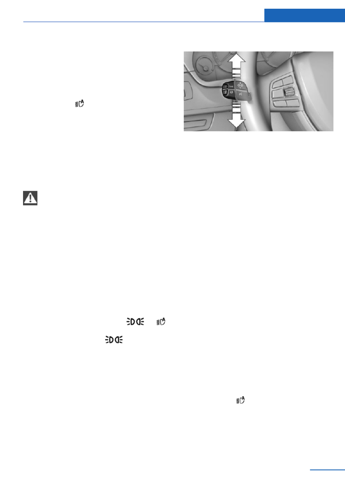
3. "Pathway lighting:"
4. Set the duration.
The setting is stored for the remote control
currently in use.
Automatic headlamp control
Switch position : the low beams are
switched on and off automatically, e.g., in tun‐
nels, in twilight or if there is precipitation. The
indicator lamp in the instrument cluster lights
up.
A blue sky with the sun low on the horizon can
cause the lights to be switched on.
The low beams always stay on when the fog
lamps are switched on.
Personal responsibility
The automatic headlamp control cannot
serve as a substitute for your personal judg‐
ment in determining when the lamps should be
switched on in response to ambient lighting
conditions.
For example, the sensors are unable to detect
fog or hazy weather. To avoid safety risks, you
should always switch on the lamps manually
under these conditions.◀
Daytime running lights
With the ignition switched on, the daytime run‐
ning lights light up in position 0, or .
After the ignition is switched off, the parking
lamps light up in position .
Activating/deactivating
In some countries, daytime running lights are
compulsory, so it may not be possible to deac‐
tivate the daytime running lights.
1. "Settings"
2. "Lighting"
3. "Daytime running lamps"
The setting is stored for the remote control
currently in use.
Roadside parking lamps
The vehicle can be illuminated on one side.
Switching on
With the ignition switched off, press the lever
either up or down past the resistance point for
approx. 2 seconds.
Switching off
Briefly press the lever to the resistance point in
the opposite direction.
Adaptive Light Control
The concept
Adaptive Light Control is a variable headlamp
control system that enables dynamic illumina‐
tion of the road surface.
Depending on the steering angle and other pa‐
rameters, the light from the headlamp follows
the course of the road.
In tight curves, e.g., on mountainous roads or
when turning, one of the two front fog lamps is
switched on as a cornering lamp. As a result
the inside of the curve is better lighted.
Activating
Switch position with the ignition switched
on.
The cornering lamps are automatically
switched on depending on the steering angle
or the use of turn signals.
Lamps Controls
91
Online Edition for Part no. 01 40 2 925 793 - II/14

To avoid blinding oncoming traffic, the Adap‐
tive Light Control does not swivel to the driv‐
er's side when the vehicle is at a standstill.
When driving in reverse, only the cornering
lamp is active.
Malfunction
A Check Control message is displayed.
Adaptive light control is malfunctioning or has
failed. Have the system checked as soon as
possible.
High-beam Assistant
The concept
When the low beams are switched on, this sys‐
tem automatically switches the high beams on
and off or suppresses the light in the areas that
blind oncoming traffic. The procedure is con‐
trolled by a sensor on the front of the interior
rearview mirror. The assistant ensures that the
high beams are switched on whenever the traf‐
fic situation allows. The driver can intervene at
any time and switch the high beams on and off
as usual.
Activating
The High-beam Assistant can be activated
when the low beams are switched on.
1. Turn the light switch to or .
2. Press the button on the turn signal lever,
arrow.
The indicator lamp in the instrument
cluster lights up.
When the low beams are on, the lights are au‐
tomatically brightened or dimmed.
The system responds to light from oncoming
traffic and traffic driving ahead of you, and to
adequate illumination, e.g., in towns and cities.
The blue indicator lamp in the instru‐
ment cluster lights up when the system
switches on the high beams. Depend‐
ing on the version of the system in the vehicle,
the high beams may not switch off for oncom‐
ing vehicles, but may only be dimmed in the
areas that blind oncoming traffic. In this case,
the blue indicator light will stay on.
Switching the high beams on and off
manually
▷High beams on, arrow 1.
▷High beams off/headlamp flasher, arrow 2.
The High-beam Assistant can be switched off
when manually adjusting the light. To reacti‐
vate the High-beam Assistant, press the but‐
ton on the turn signal lever.
System limits
Personal responsibility
The high-beam assistant cannot serve as
a substitute for the driver's personal judgment
of when to use the high beams. Therefore,
manually switch off the high beams in situa‐
tions where this is required to avoid a safety
risk.◀
Controls Lamps
92 Online Edition for Part no. 01 40 2 925 793 - II/14
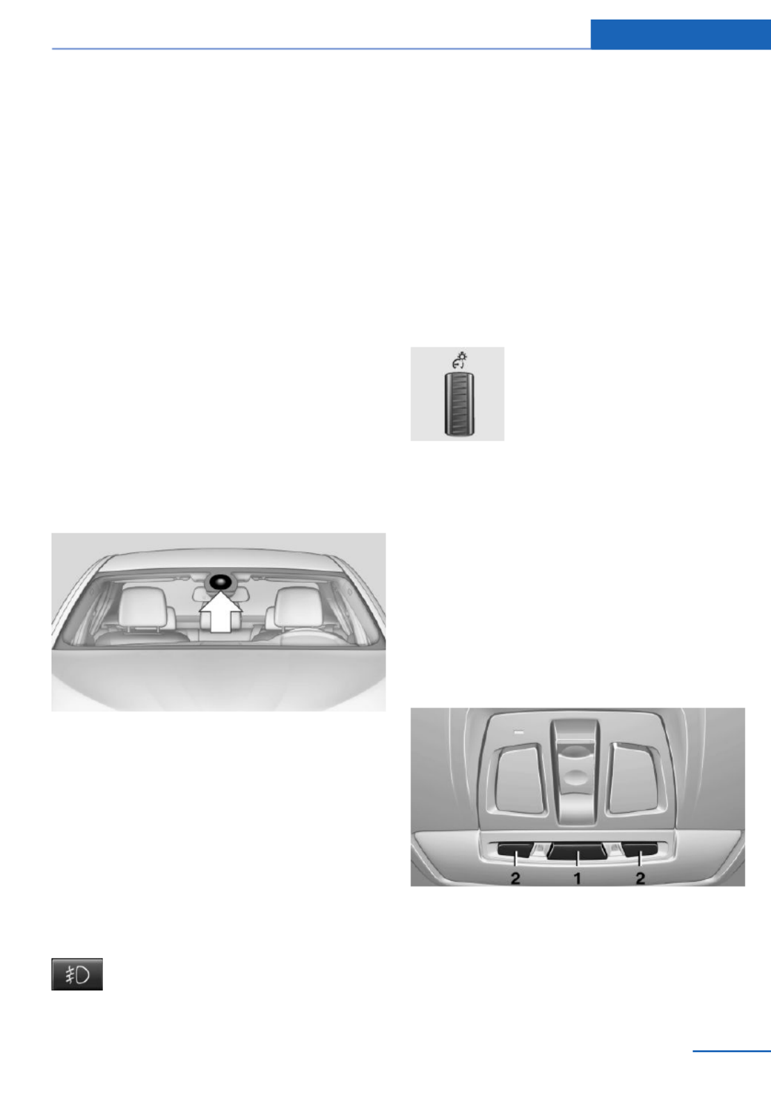
The system is not fully functional in situations
such as the following, and driver intervention
may be necessary:
▷In very unfavorable weather conditions,
such as fog or heavy precipitation.
▷In detecting poorly-lit road users, such as
pedestrians, cyclists, horseback riders and
wagons; when driving close to train or ship
traffic; and at animal crossings.
▷In tight curves, on hilltops or in depres‐
sions, in cross traffic or half-obscured on‐
coming traffic on freeways.
▷In poorly-lit towns and cities and in the
presence of highly reflective signs.
▷At low speeds.
▷When the windshield behind the interior
rearview mirror is fogged over, dirty or cov‐
ered with stickers, etc.
Camera
The camera is located near the base of the
mirror.
Keep the windshield in the area behind the in‐
terior rear view mirror clean and clear.
Fog lamps
Front fog lamps
The low beams must be switched on.
Press the button. The green indicator
lamp lights up.
If the automatic headlamp control, refer to
page , is activated, the low beams will come91
on automatically when you switch on the front
fog lamps.
When the high beams or headlamp flasher are
activated, the front fog lamps are not switched
on.
Instrument lighting
Adjusting
The parking lamps or low beams
must be switched on to adjust
the brightness.
Adjust the brightness using the
thumbwheel.
Interior lamps
General information
The interior lamps, footwell lamps, entry lamps
and courtesy lamps are controlled automati‐
cally.
The brightness of some of these lamps is influ‐
enced by the thumbwheel for the instrument
lighting.
1Interior lamps
2Reading lamp
Lamps Controls
93
Online Edition for Part no. 01 40 2 925 793 - II/14

Switching the interior lamps on and
off
Press the button.
To switch off permanently: press the button for
approx. 3 seconds.
Switch back on: press button.
Reading lamps
Press the button.
Reading lamps are located at the front and rear
next to the interior lamps.
Ambient light
Depending on the equipment, the lighting can
be adjusted in the interior for some lights.
Selecting color scheme
1. "Settings"
2. "Lighting"
3. "Ambient:"
4. Select the desired setting.
If the color scheme of the line is selected and
the welcome lamps are activated, the welcome
lamps are displayed in the color of the line
when the vehicle is unlocked.
Setting the brightness
The brightness of the ambient light can be ad‐
justed via the thumbwheel for the instrument
lighting or on the Control Display.
1. "Settings"
2. "Lighting"
3. "Brightness:"
4. Adjust the brightness.
Controls Lamps
94 Online Edition for Part no. 01 40 2 925 793 - II/14

Safety
Vehicle equipment
All standard, country-specific and optional
equipment that is offered in the model series is
described in this chapter. Therefore, equip‐
ment is also described that is not available in a
vehicle, e. g., because of the selected optional
equipment or country variant. This also applies
for safety-related functions and systems.
Airbags
1Front airbag, driver
2Front airbag, front passenger
3Head airbag
4Side airbag
5Knee airbags
Front airbags
Front airbags help protect the driver and front
passenger by responding to frontal impacts in
which safety belts alone cannot provide ade‐
quate restraint.
Side airbags
In a lateral impact, the side airbag supports the
side of the body in the chest and lap area.
Head airbags
In a lateral impact, the head airbag supports
the head.
Knee airbag
The knee airbag supports the legs in a frontal
impact.
Safety Controls
95
Online Edition for Part no. 01 40 2 925 793 - II/14

Protective action
Airbags are not triggered in every impact situa‐
tion, e.g., in less severe accidents or rear-end
collisions.
Information on how to ensure the optimal
protective effect of the airbags
▷Keep at a distance from the airbags.
▷Always grasp the steering wheel on the
steering wheel rim, holding your hands at
the 3 o'clock and 9 o'clock positions, to
keep the danger of injury to your hands or
arms as low as possible if the airbag is trig‐
gered.
▷There should be no people, animals, or ob‐
jects between an airbag and a person.
▷Do not use the cover of the front airbag on
the front passenger side as a storage area.
▷Keep the dashboard and window on the
front passenger side clear, i.e. do not cover
with adhesive labels or coverings, and do
not attach holders such as for navigation
instruments and mobile phones.
▷Make sure that the front passenger is sit‐
ting correctly, i.e., keeps his or her feet and
legs in the footwell; otherwise, leg injuries
can occur if the front airbag is triggered.
▷Do not place slip covers, seat cushions or
other objects on the front passenger seat
that are not approved specifically for seats
with integrated side airbags.
▷Do not hang pieces of clothing, such as
jackets, over the backrests.
▷Make sure that occupants keep their heads
away from the side airbag and do not rest
against the head airbag; otherwise, injuries
can occur if the airbags are triggered.
▷Do not remove the airbag restraint system.
▷Do not remove the steering wheel.
▷Do not apply adhesive materials to the air‐
bag cover panels, cover them or modify
them in any way.
▷Never modify either the individual compo‐
nents or the wiring in the airbag system.
This also applies to steering wheel covers,
the dashboard, the seats, the roof pillars
and the sides of the headliner.◀
Even when all instructions are followed closely,
injury from contact with the airbags cannot be
ruled out in certain situations.
The ignition and inflation noise may lead to
short-term and, in most cases, temporary
hearing impairment in sensitive individuals.
In the case of a malfunction, deactivation
and after triggering of the airbags
Do not touch the individual components imme‐
diately after the system has been triggered;
otherwise, there is the danger of burns.
Only have the airbags checked, repaired or dis‐
mantled and the airbag generator scrapped by
the service center or a workshop that has the
necessary authorization for handling explo‐
sives.
Non-professional attempts to service the sys‐
tem could lead to failure in an emergency or
undesired triggering of the airbag, either of
which could result in injury.◀
Warnings and information on the airbags are
also found on the sun visors.
Functional readiness of the airbag
system
When the ignition is switched on, the
warning lamp in the instrument cluster
lights up briefly and thereby indicates
the operational readiness of the entire airbag
system and the belt tensioner.
Airbag system malfunctioning
▷Warning lamp does not come on when the
ignition is turned on.
▷The warning lamp lights up continuously.
Controls Safety
96 Online Edition for Part no. 01 40 2 925 793 - II/14

When there is a malfunction, have the
airbag system checked immediately
When there is a malfunction, have the airbag
system checked immediately; otherwise, there
is a risk that the system does not function as
expected in the event of an accident despite
corresponding severity of the accident.◀
Automatic deactivation of the front
passenger airbags
The system determines whether the front pas‐
senger seat is occupied by measuring the re‐
sistance of the human body.
The front, knee, and side airbag on the front
passenger side are activated or deactivated
accordingly.
Leave feet in the footwell
Make sure that the front passenger
keeps his or her feet in the footwell; otherwise,
the front passenger airbags may not function
properly.◀
Child restraint fixing system in the front
passenger seat
Before transporting a child on the front pas‐
senger seat, refer to the safety notes and in‐
structions under Children on the front passen‐
ger seat.◀
Malfunction of the automatic
deactivation system
When transporting older children and adults,
the front passenger airbags may be deacti‐
vated in certain sitting positions. In this case,
the indicator lamp for the front passenger air‐
bags lights up.
In this case, change the sitting position so that
the front passenger airbags are activated and
the indicator lamp goes out.
If it is not possible to activate the airbags, have
the person sit in the rear.
To make sure that the occupied seat cushion
can be evaluated correctly
▷Do not attach covers, cushions, ball mats
or other items to the front passenger seat
unless they are specifically recommended
by the manufacturer of your vehicle.
▷Do not place any electronic devices on the
passenger seat if a child restraint system is
to be installed on it.
▷Do not place objects under the seat that
could press against the seat from below.
▷No moisture in or on the seat.
Indicator lamp for the front passenger
airbags
The indicator lamp for the front passenger air‐
bags indicates the operating state of the front
passenger airbags.
The lamp indicates whether the airbags are ac‐
tivated or deactivated.
▷The indicator lamp lights up
when a child who is properly
seated in a child restraint fix‐
ing system intended for that
purpose is detected on the
seat or the seat is empty.
The airbags on the front
passenger side are not acti‐
vated.
▷The indicator lamp does not light up when,
for example, a correctly seated person of
sufficient size is detected on the seat. The
airbags on the front passenger side are ac‐
tivated.
Safety Controls
97
Online Edition for Part no. 01 40 2 925 793 - II/14

Detected child seats
The system generally detects children seated
in a child seat, especially in the child seats that
were required by NHTSA when the vehicle was
manufactured. After installing a child seat,
make sure that the indicator lamp for the front
passenger airbags lights up. This indicates
that the child seat has been detected and the
front passenger airbags are not activated.
Strength of the driver's and front
passenger airbag
The strength with which the driver's and front
passenger airbags are triggered depends on
the position of the driver's and front passenger
seats.
To maintain the accuracy of this function over
the long-term, calibrate the front seats when a
corresponding message appears on the Con‐
trol Display.
Calibrating the front seats
A corresponding message appears on the
Control Display.
1. Move the respective seat forward all the
way.
2. Move the respective seat forward again. It
moves forward briefly.
3. Readjust the seat to the desired position.
The calibration procedure is completed when
the message on the Control Display disap‐
pears.
If the message continues to be displayed, re‐
peat the calibration.
If the message does not disappear after a re‐
peat calibration, have the system checked as
soon as possible.
Unobstructed area of movement
Ensure that the area of movement of the
seats is unobstructed to avoid personal injury
or damage to objects.◀
Tire Pressure Monitor TPM
The concept
The system monitors tire pressure in the four
mounted tires. The system warns you if there
is a significant loss of pressure in one or more
tires. For this purpose, sensors in the tire
valves measure the tire inflation pressure.
Hints
Tire damage due to external factors
Sudden tire damage caused by external
influences cannot be indicated in advance.◀
Pay attention to the other information and indi‐
cations under Tire inflation pressure, refer to
page , as well when using the system.191
Functional requirements
The system must have been reset with the
correct tire inflation pressure; otherwise, relia‐
ble signaling of tire pressure loss is not en‐
sured.
Reset the system after each adjustment of the
tire inflation pressure and after every tire or
wheel change.
Always use wheels with TPM electronics to
ensure that the system will operate properly.
Status display
The current status of the Tire Pressure Moni‐
tor TPM can be displayed on the Control Dis‐
play, e.g., whether or not the TPM is active.
1. "Vehicle Info"
2. "Vehicle status"
3. "Tire Pressure Monitor (TPM)"
The status is displayed.
Status control display
The tire and system status is indicated by the
color of the wheels and a text message on the
Control Display.
Controls Safety
98 Online Edition for Part no. 01 40 2 925 793 - II/14

All wheels green
System is active and will issue a warning rela‐
tive to the tire inflation pressures stored during
the last reset.
One wheel is yellow
A flat tire or major drop in inflation pressure in
the indicated tire.
All wheels are yellow
A flat tire or major drop in inflation pressure in
several tires.
Wheels, gray
The system cannot detect a flat tire. Reasons
for this may be:
▷The system is being reset.
▷Malfunction.
Carry out reset
Reset the system after each adjustment of the
tire inflation pressure and after every tire or
wheel change.
1. "Vehicle Info"
2. "Vehicle status"
3. "Perform reset"
4. Start the engine - do not drive away.
5. Carry out the reset with "Perform reset".
6. Drive away.
The tires are shown in gray and the status is
displayed.
After driving faster than 19 mph/30 km/h for a
short period, the tire inflation pressures set are
accepted as reference values. The reset is
completed automatically during driving.
After a successfully completed Reset, the
wheels on the Control Display are shown in
green and "Tire Pressure Monitor (TPM)
active" is displayed.
The trip can be interrupted at any time. If you
drive away again, the reset resumes automati‐
cally.
Low tire pressure message
The yellow warning lamp lights up. A
Check Control message is displayed.
▷There is a flat tire or a major loss in
tire inflation pressure.
▷No reset was performed for the system.
The system therefore issues a warning
based on the tire inflation pressures before
the last reset.
1. Reduce your speed and stop cautiously.
Avoid sudden braking and steering maneu‐
vers.
2. Check whether the vehicle is fitted with
regular tires or run-flat tires.
Run-flat tires, refer to page , are la‐197
beled with a circular symbol containing the
letters RSC marked on the tire sidewall.
Do not continue driving without run-flat
tires
Do not continue driving if the vehicle is not
equipped with run-flat tires; continued driving
may result in serious accidents.◀
When a low inflation pressure is indicated,
DSC Dynamic Stability Control is switched on
if necessary.
Actions in the event of a flat tire
Normal tires
1. Identify the damaged tire.
Do this by checking the air pressure in all
four tires.
If the tire inflation pressure in all four tires
is correct, it is possible that a reset was not
carried out for the Tire Pressure Monitor.
Then perform the reset.
Safety Controls
99
Online Edition for Part no. 01 40 2 925 793 - II/14

If an identification is not possible, please
contact the service center.
2. Fix the flat tire.
Run-flat tires
Maximum speed
You can continue driving with a damaged tire
at speeds up to 50 mph/80 km/h.
Continued driving with a flat tire
If continuing to drive with a damaged tire:
1. Avoid sudden braking and steering maneu‐
vers.
2. Do not exceed a speed of 50 mph/80 km/h.
3. Check the air pressure in all four tires at
the next opportunity.
If the tire inflation pressure in all four tires
is correct, it is possible that a reset was not
carried out for the Tire Pressure Monitor. In
that case, carry out a reset.
Possible driving distance with complete loss of
tire inflation pressure:
The possible driving distance after a loss of tire
inflation pressure depends on the cargo load
and the driving style and conditions.
For a vehicle containing an average load, the
possible driving distance is approx.
50 miles/80 km.
When the vehicle is driven with a damaged tire,
its handling characteristics change, e.g., re‐
duced lane stability during braking, a longer
braking distance, and altered self-steering
properties. Adjust your driving style accord‐
ingly. Avoid abrupt steering maneuvers or driv‐
ing over obstacles, e.g., curbs, potholes, etc.
Because the possible driving distance de‐
pends on how the vehicle is used during the
trip, the actual distance may be smaller or
greater depending on the driving speed, road
conditions, external temperature, cargo load,
etc.
Continued driving with a flat tire
Drive moderately and do not exceed a
speed of 50 mph/80 km/h.
A loss of tire inflation pressure results in a
change in the handling characteristics, e.g., re‐
duced lane stability during braking, a longer
braking distance and altered self-steering
properties.◀
Final tire failure
Vibrations or loud noises while driving
can indicate the final failure of the tire. Reduce
speed and stop; otherwise, pieces of the tire
could come loose and cause an accident. Do
not continue driving, and contact your service
center.◀
Required inflation pressure check
message
A Check Control message is displayed in the
following situations
▷The system has detected a wheel change,
but no reset was carried out.
▷Inflation was not carried out according to
specifications.
▷The tire pressure has fallen below the level
of the last confirmation.
In this case:
▷Check the tire pressure and correct as
needed.
▷Carry out a reset of the system after a tire
change.
System limits
The system does not function properly if a re‐
set has not been carried out, e.g., a flat tire is
reported even though the tire inflation pres‐
sures are correct.
The tire pressure depends on the temperature
of the tire. If the tire temperature rises, e.g.,
due to driving or because of the heat of the
Sun, the tire inflation pressure increases also.
The tire pressure is reduced when the tire
Controls Safety
100 Online Edition for Part no. 01 40 2 925 793 - II/14

temperature falls again. This behavior may
cause a warning to be issued if temperatures
fall very sharply.
Malfunction
The yellow warning lamp flashes and
then lights up continuously. A Check
Control message is displayed. No flat
tire or loss of tire pressure can be detected.
Display in the following situations:
▷A wheel without TPM electronics is fitted:
have the service center check it if neces‐
sary.
▷Malfunction: have the system checked by
your service center.
▷TPM was unable to complete the reset.
Reset the system again.
▷Disturbance by systems or devices with
the same radio frequency: after leaving the
area of the disturbance, the system auto‐
matically becomes active again.
Declaration according to NHTSA/
FMVSS 138 Tire Pressure Monitoring
System
Each tire, including the spare (if provided)
should be checked monthly when cold and in‐
flated to the inflation pressure recommended
by the vehicle manufacturer on the vehicle
placard or tire inflation pressure label. (If your
vehicle has tires of a different size than the size
indicated on the vehicle placard or tire inflation
pressure label, you should determine the
proper tire inflation pressure for those tires.)
As an added safety feature, your vehicle has
been equipped with a tire pressure monitoring
system (TPMS) that illuminates a low tire pres‐
sure telltale when one or more of your tires is
significantly under-inflated. Accordingly, when
the low tire pressure telltale illuminates, you
should stop and check your tires as soon as
possible, and inflate them to the proper pres‐
sure. Driving on a significantly under-inflated
tire causes the tire to overheat and can lead to
tire failure. Under-inflation also reduces fuel ef‐
ficiency and tire tread life, and may affect the
vehicle's handling and stopping ability. Please
note that the TPMS is not a substitute for
proper tire maintenance, and it is the driver's
responsibility to maintain correct tire pressure,
even if under-inflation has not reached the
level to trigger illumination of the TPMS low
tire pressure telltale. Your vehicle has also
been equipped with a TPMS malfunction indi‐
cator to indicate when the system is not oper‐
ating properly. The TPMS malfunction indica‐
tor is combined with the low tire pressure
telltale. When the system detects a malfunc‐
tion, the telltale will flash for approximately one
minute and then remain continuously illumi‐
nated. This sequence will continue upon sub‐
sequent vehicle start-ups as long as the mal‐
function exists. When the malfunction indicator
is illuminated, the system may not be able to
detect or signal low tire pressure as intended.
TPMS malfunctions may occur for a variety of
reasons, including the installation of replace‐
ment or alternate tires or wheels on the vehicle
that prevent the TPMS from functioning prop‐
erly. Always check the TPMS malfunction tell‐
tale after replacing one or more tires or wheels
on your vehicle to ensure that the replacement
or alternate tires and wheels allow the TPMS
to continue to function properly.
FTM Flat Tire Monitor
The concept
The system detects a pressure loss on the ba‐
sis of speed differences between the individual
wheels while driving.
In the event of a pressure loss, the diameter
and therefore the rotational speed of the corre‐
sponding wheel change. This is detected and
reported as a flat tire.
The system does not measure the actual infla‐
tion pressure in the tires.
Safety Controls
101
Online Edition for Part no. 01 40 2 925 793 - II/14

Functional requirements
The system must have been initialized when
the tire inflation pressure was correct; other‐
wise, reliable signaling of a flat tire is not en‐
sured. Initialize the system after each correc‐
tion of the tire inflation pressure and after
every tire or wheel change.
Status display
The current status of the Flat Tire Monitor can
be displayed on the Control Display, e.g.,
whether or not the FTM is active.
1. "Vehicle Info"
2. "Vehicle status"
3. "Flat Tire Monitor (FTM)"
The status is displayed.
Initialization
The initialization process adopts the set infla‐
tion tire pressures as reference values for the
detection of a flat tire. Initialization is started by
confirming the inflation pressures.
Do not initialize the system when driving with
snow chains.
1. "Vehicle Info"
2. "Vehicle status"
3. "Perform reset"
4. Start the engine - do not drive away.
5. Start the initialization with "Perform reset".
6. Drive away.
The initialization is completed while driving,
which can be interrupted at any time.
The initialization automatically continues when
driving resumes.
Indication of a flat tire
The yellow warning lamp lights up. A
Check Control message is displayed.
There is a flat tire or a major loss in tire inflation
pressure.
1. Reduce your speed and stop cautiously.
Avoid sudden braking and steering maneu‐
vers.
2. Check whether the vehicle is fitted with
regular tires or run-flat tires.
Run-flat tires, refer to page , are la‐197
beled with a circular symbol containing the
letters RSC marked on the tire sidewall.
Do not continue driving without run-flat
tires
Do not continue driving if the vehicle is not
equipped with run-flat tires; continued driving
may result in serious accidents.◀
When a flat tire is indicated, DSC Dynamic Sta‐
bility Control is switched on if necessary.
System limits
Sudden tire damage
Sudden serious tire damage caused by
external influences cannot be indicated in ad‐
vance.◀
A natural, even pressure loss in all four tires
cannot be detected. Therefore, check the tire
inflation pressure regularly.
The system could be delayed or malfunction in
the following situations:
▷When the system has not been initialized.
▷When driving on a snowy or slippery road
surface.
▷Sporty driving style: slip in the drive
wheels, high lateral acceleration.
▷When driving with snow chains.
Actions in the event of a flat tire
Normal tires
1. Identify the damaged tire.
Do this by checking the air pressure in all
four tires.
Controls Safety
102 Online Edition for Part no. 01 40 2 925 793 - II/14

If the tire inflation pressure in all four tires
is correct, the Flat Tire Monitor may not
have been initialized. In this case, initialize
the system.
If an identification is not possible, please
contact the service center.
2. Rectify the flat tire.
Run-flat tires
Maximum speed
You can continue driving with a damaged tire
at speeds up to 50 mph/80 km/h.
Continued driving with a flat tire
If continuing to drive with a damaged tire:
1. Avoid sudden braking and steering maneu‐
vers.
2. Do not exceed a speed of 50 mph/80 km/h.
3. Check the air pressure in all four tires at
the next opportunity.
If the tire inflation pressure in all four tires
is correct, the Flat Tire Monitor may not
have been initialized. In this case, initialize
the system.
Possible driving distance with complete loss of
tire inflation pressure:
The possible driving distance after a loss of tire
inflation pressure depends on the cargo load
and the driving style and conditions.
For a vehicle containing an average load, the
possible driving distance is approx.
50 miles/80 km.
When the vehicle is driven with a damaged tire,
its handling characteristics change, e.g., re‐
duced lane stability during braking, a longer
braking distance, and altered self-steering
properties. Adjust your driving style accord‐
ingly. Avoid abrupt steering maneuvers or driv‐
ing over obstacles, e.g., curbs, potholes, etc.
Because the possible driving distance de‐
pends on how the vehicle is used during the
trip, the actual distance may be smaller or
greater depending on the driving speed, road
conditions, external temperature, cargo load,
etc.
Continued driving with a flat tire
Drive moderately and do not exceed a
speed of 50 mph/80 km/h.
A loss of tire inflation pressure results in a
change in the handling characteristics, e.g., re‐
duced lane stability during braking, a longer
braking distance and altered self-steering
properties.◀
Final tire failure
Vibrations or loud noises while driving
can indicate the final failure of the tire. Reduce
speed and stop; otherwise, pieces of the tire
could come loose and cause an accident. Do
not continue driving, and contact your service
center.◀
Intelligent Safety
The concept
Depending on how the vehicle is equipped, In‐
telligent Safety consists of one or more of the
following systems, which can help to avoid an
imminent collision. These systems are active
automatically every time the engine is started
using the Start/Stop button:
▷Collision warning, refer to page .104
▷Pedestrian warning, refer to page .109
Note
Personal responsibility
The system does not serve as a substi‐
tute for the driver's personal judgment of the
traffic situation.
Be aware of the traffic situation and the vehi‐
cle's surroundings at all times, otherwise an
accident is still possible despite all warnings.◀
Safety Controls
103
Online Edition for Part no. 01 40 2 925 793 - II/14

Detection range
Vehicles are observed when they are traveling
in the same direction of movement if they are
located within the detection range of the sys‐
tem.
At a glance
Button in the vehicle
Intelligent Safety button
Camera
The camera is located near the base of the
mirror.
Keep the windshield in the area behind the in‐
terior rear view mirror clean and clear.
Switching on/off
Switching on automatically
The system is automatically active every time
the engine is started using the Start/Stop but‐
ton.
Switching off
Press button: the system is switched
off. The LED goes out.
Re-press button: the system is switched on.
The LED lights up.
Setting the prewarning time
The prewarning time can be set via iDrive.
1. "Settings"
2. "Frontal Coll. Warning"
3. Activate the desired time on the Control
Display.
The selected time is stored for the remote
control currently in use.
Warning with braking function
Note
Adapting your speed and driving style
The warning does not relieve the driver
of the responsibility to adapt his or her driving
speed and style to the traffic conditions.◀
Display
If a collision with a vehicle detected in this way
is imminent, a warning symbol appears on the
instrument cluster and in the Head-up Display.
Safety Controls
105
Online Edition for Part no. 01 40 2 925 793 - II/14
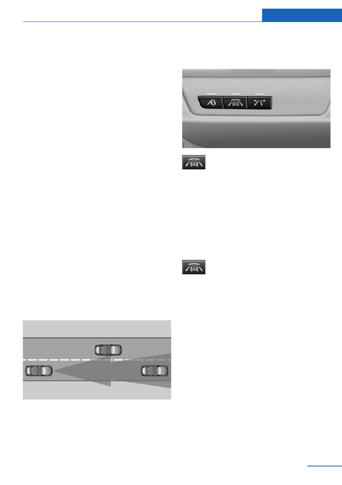
Prewarning sensitivity
Depending on the set prewarning time, this
may result in increased false warnings.
Collision warning with
braking function
The concept
The system issues a warning if there is immi‐
nent danger of a collision and also includes a
braking function.
If the vehicle is equipped with Active Cruise
Control with Stop & Go, the collision warning is
controlled via the cruise control radar sensor.
The collision warning is available even if cruise
control has been deactivated.
When the vehicle is intentionally brought close
to a vehicle, the collision warning is delayed to
avoid false warnings.
General information
The system issues a two-phase warning of a
possible danger of collision with vehicles at
speeds above approx. 3 mph/5 km/h. The time
of these warnings may vary depending on the
current driving situation.
Detection range
It responds to objects if they are detected by
the radar.
At a glance
Button in the vehicle
Intelligent Safety button
Switching on/off
Switching on automatically
The system is automatically active every time
the engine is started using the Start/Stop but‐
ton.
Switching off
Press button: the system is switched
off. The LED goes out.
Re-press button: the system is switched on.
The LED lights up.
Setting the prewarning time
The prewarning time can be set via iDrive.
1. "Settings"
2. "Frontal Coll. Warning"
3. Activate the desired time on the Control
Display.
The selected time is stored for the remote
control currently in use.
Safety Controls
107
Online Edition for Part no. 01 40 2 925 793 - II/14
Display
Warning stages
Prewarning
This warning is issued, for example, when
there is the impending danger of a collision or
the distance to the vehicle ahead is too small.
Acute warning with braking function
Warning of the imminent danger of a collision
when the vehicle approaches another object at
a relatively high differential speed.
The driver must intervene actively when there
is an acute warning. If necessary, the driver is
assisted by an automatic braking intervention
in a possible risk of collision.
The detection of objects can be influeneced by
technical system limitations, e. g. pedestrians
or stationary objects. Limitations of the detec‐
tion range and functional restricitions are to be
considered.
The braking intervention is executed with lim‐
ited braking force and for a brief period only.
The intervention can bring the vehicle to a
complete stop.
The braking intervention is executed only if
DSC Dynamic Stability Control is switched on
and Dynamic Traction Control DTC is acti‐
vated.
Above approx. 130 mph/210 km/h, the braking
intervention occurs as a brief braking pressure.
No automatic delay occurs.
Adapting your speed and driving style
The warning does not relieve the driver
of the responsibility to adapt his or her driving
speed and style to the traffic conditions.◀
The braking intervention can be interrupted by
pressing on the accelerator pedal or by actively
moving the steering wheel.
Tow-starting and towing
When tow-starting and towing the vehi‐
cle, switch off the Intelligent Safety systems;
otherwise, improper behavior of the braking
function of individual systems could result in
an accident.◀
Display in the instrument cluster
The collision warning can be issued in the in‐
strument cluster, in the Head-up Display, and
acoustically.
Warning stages
Symbol Measure
The vehicle lights up red: prewarn‐
ing.
Increase distance.
The vehicle flashes red and an
acoustic signal sounds: acute warn‐
ing.
You are requested to intervene by
braking or making an evasive ma‐
neuver.
Adapting your speed and driving style
The display does not relieve the driver of
the responsibility to adapt his or her driving
speed and style to the traffic conditions.◀
System limits
Be alert
Due to system limitations, warnings may
be not be issued at all, or may be issued late or
improperly. Therefore, always be alert and
ready to intervene; otherwise, there is the dan‐
ger of an accident occurring.◀
Detection range
The system's detection capabilities are limited.
Controls Safety
108 Online Edition for Part no. 01 40 2 925 793 - II/14

The lamp in the exterior mirror housing lights
up dimly.
Before you change lanes after setting the turn
signal, the system issues a warning in the sit‐
uations described above.
The lamp in the housing of the exterior mirror
flashes and the steering wheel vibrates.
Hints
Personal responsibility
The system does not serve as a substi‐
tute for the driver's personal judgment of the
traffic situation.
Be aware of the traffic situation and the vehi‐
cle's surroundings at all times, otherwise an
accident is still possible despite all warnings.◀
At a glance
Button in the vehicle
Active Blind Spot Detection
Radar sensors
The radar sensors are located under the rear
bumper.
Switching on/off
Press the button.
▷On: the LED lights up.
▷Off: the LED goes out.
The system can issue warnings at speeds
above approx. 30 mph/50 km/h.
The setting is stored for the remote control
currently in use.
Display
Information stage
The dimmed lamp in the mirror housing indi‐
cates when there are vehicles in the blind spot
or approaching from behind.
Warning
If the turn signal is set while a vehicle is in the
critical zone, the steering wheel vibrates briefly
Safety Controls
113
Online Edition for Part no. 01 40 2 925 793 - II/14
Driving stability control systems
Vehicle equipment
All standard, country-specific and optional
equipment that is offered in the model series is
described in this chapter. Therefore, equip‐
ment is also described that is not available in a
vehicle, e. g., because of the selected optional
equipment or country variant. This also applies
for safety-related functions and systems.
Antilock Brake System ABS
ABS prevents locking of the wheels during
braking.
The vehicle remains steerable even during full
brake applications, thus increasing active
safety.
ABS is operational every time you start the en‐
gine.
Brake assistant
When you apply the brakes rapidly, this system
automatically produces the maximum braking
force boost. This then reduces braking dis‐
tance to a minimum during full braking. This
system utilizes all of the benefits provided by
ABS.
Do not reduce the pressure on the brake pedal
for the duration of the full braking.
DSC Dynamic Stability
Control
The concept
DSC prevents traction loss in the driving
wheels when driving away and accelerating.
DSC also recognizes unstable vehicle condi‐
tions, such as fishtailing or nose-diving. Sub‐
ject to physical limits, DSC helps to keep the
vehicle on a steady course by reducing engine
speed and by applying brakes to the individual
wheels.
Adjust your driving style to the situation
An appropriate driving style is always the
responsibility of the driver.
The laws of physics cannot be repealed, even
with DSC.
Therefore, do not reduce the additional safety
margin by driving in a risky manner.◀
Indicator/warning lamps
The indicator lamp flashes: DSC con‐
trols the drive forces and brake forces.
The indicator lamp lights up: DSC has
failed.
Deactivating DSC: DSC OFF
When DSC is deactivated, driving stability is
reduced during acceleration and when driving
in bends.
To increase vehicle stability, activate DSC
again as soon as possible.
Deactivating DSC
Press and hold the button, but not lon‐
ger than approx. 10 seconds, until the
indicator lamp for DSC OFF lights up in the in‐
strument cluster and DSC OFF is displayed.
The DSC system is switched off.
Steering and, depending on the equipment,
the chassis are adjusted for sporty driving.
Activating DSC
Press the button.
Driving stability control systems Controls
115
Online Edition for Part no. 01 40 2 925 793 - II/14

DSC OFF and the DSC OFF indicator lamp go
out.
Indicator/warning lamps
When DSC is deactivated, DSC OFF is dis‐
played in the instrument cluster.
The indicator lamp lights up: DSC is
deactivated.
DTC Dynamic Traction
Control
The concept
The DTC system is a version of the DSC in
which forward momentum is optimized.
The system ensures maximum forward mo‐
mentum on special road conditions, e.g., unp‐
lowed snowy roads, but driving stability is lim‐
ited.
It is therefore necessary to drive with appropri‐
ate caution.
You may find it useful to briefly activate DTC
under the following special circumstances:
▷When driving in slush or on uncleared,
snow-covered roads.
▷When rocking the vehicle or driving off in
deep snow or on loose surfaces.
▷When driving with snow chains.
Deactivating/activating DTC Dynamic
Traction Control
Activating the Dynamic Traction Control DTC
provides maximum traction on loose ground.
Driving stability is limited during acceleration
and when driving in bends.
Activating DTC
Press the button.
TRACTION is displayed in the instrument clus‐
ter and the indicator lamp for DSC OFF lights
up.
Deactivating DTC
Press the button again.
TRACTION and the DSC OFF indica‐
tor lamp go out.
xDrive
xDrive is the all-wheel-drive system of your ve‐
hicle. Concerted action by the xDrive and DSC
further optimize traction and driving dynamics.
The xDrive all-wheel-drive system variably dis‐
tributes the drive forces to the front and rear
axles as demanded by the driving situation and
road surface.
Dynamic Damping Control
The concept
This system reduces undesirable vehicle mo‐
tion when using a dynamic driving style or trav‐
eling on uneven road surfaces.
The system enhances driving dynamics and
comfort as required for the road surface and
driving style.
Programs
The system offers several different programs.
The programs can be selected via the Driving
Dynamics Control, refer to page .117
SPORT
Consistently sporty control of the shock ab‐
sorbers for greater driving agility.
Controls Driving stability control systems
116 Online Edition for Part no. 01 40 2 925 793 - II/14
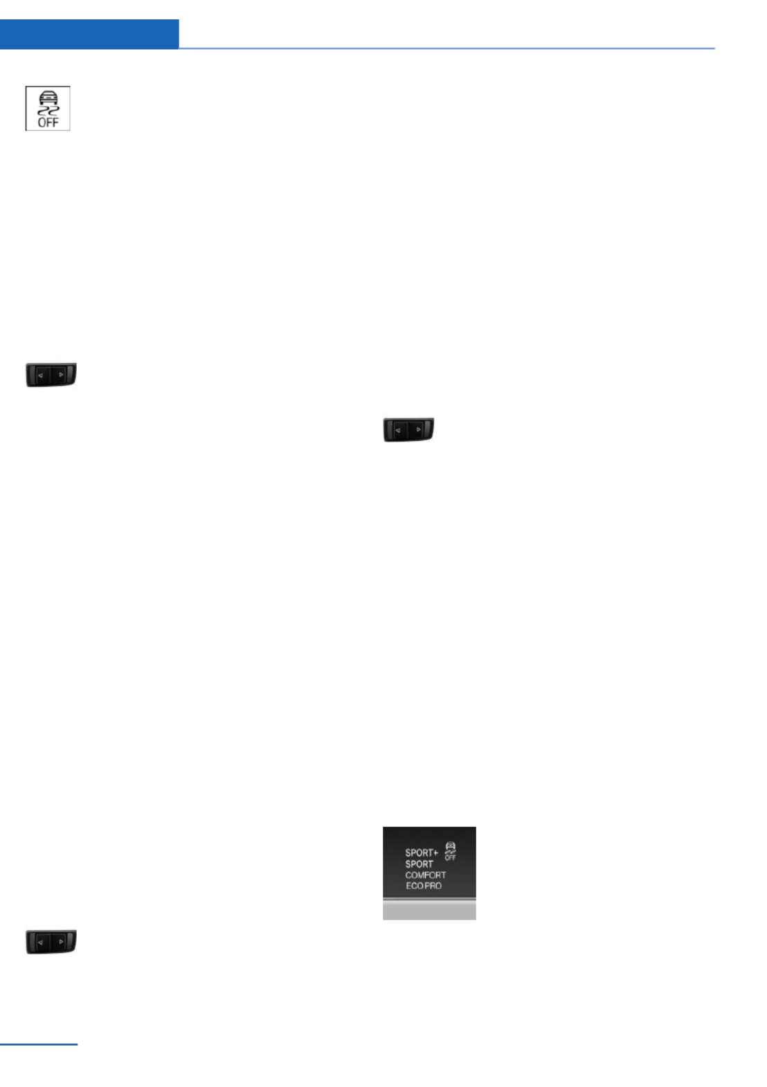
The DSC OFF indicator lamp lights up:
Dynamic Traction Control is activated.
SPORT
Consistently sporty tuning of the suspension
and engine control for greater driving agility
with maximum driving stabilization.
The program can be configured to individual
specifications. The configuration is stored for
the remote control currently in use.
Activating SPORT
Press button repeatedly until SPORT
is displayed in the instrument cluster.
Configuring SPORT
When the display is activated on the Control
Display, refer to page , the SPORT driving119
mode can be set to individual specifications.
▷Activating SPORT.
▷"Configure SPORT"
▷Configuring the SPORT driving mode.
SPORT can also be configured before it is acti‐
vated:
1. "Settings"
2. "Driving mode"
3. "Configure SPORT"
4. Configure driving mode.
This configuration is retrieved when the
SPORT driving mode is activated.
COMFORT
For a balanced tuning with maximum driving
stabilization.
Activating COMFORT
Press button repeatedly until COM‐
FORT is displayed in the instrument
cluster.
In certain situations, the system automatically
changes to the NORMAL program, automatic
program change, refer to page .117
ECO PRO
ECO PRO, refer to page , provides consis‐175
tent tuning to minimize fuel consumption for
maximum range with maximum driving stabili‐
zation.
Comfort functions and the engine controller
are adjusted.
The program can be configured to individual
specifications.
Activating ECO PRO
Press button repeatedly until ECO
PRO is displayed in the instrument
cluster.
Configuring ECO PRO
1. Activate ECO PRO.
2. "Configure ECO PRO"
Make the desired settings.
Configuring drive program
Settings can be made for the following driving
programs in Driving mode:
▷SPORT, refer to page .118
▷ECO PRO, refer to page .176
Displays
Program selection
Pressing the button displays a
list of the selectable programs.
Controls Driving stability control systems
118 Online Edition for Part no. 01 40 2 925 793 - II/14

Driving comfort
Vehicle equipment
All standard, country-specific and optional
equipment that is offered in the model series is
described in this chapter. Therefore, equip‐
ment is also described that is not available in a
vehicle, e. g., because of the selected optional
equipment or country variant. This also applies
for safety-related functions and systems.
Active Cruise Control with
Stop & Go function, ACC
The concept
This system can be used to select a desired
speed that the vehicle will maintain automati‐
cally on clear roads.
To the extent possible, the system automati‐
cally adjusts the speed to a slower vehicle
ahead of you.
The distance that the vehicle maintains to the
vehicle ahead of you can be varied.
For safety reasons, it depends on the speed.
To maintain a certain distance, the system au‐
tomatically reduces the speed, applies the
brakes lightly, or accelerates again if the vehi‐
cle ahead begins moving faster.
If the vehicle ahead of you brakes to a halt, the
system is able to detect this within the given
system limits. If the vehicle ahead of your
drives away again from a halt, your vehicle is
able to accelerate if operated accordingly.
Even if some time passes before the vehicle
ahead of you drives away again, your own vehi‐
cle can still be accelerated automatically and
simply.
As soon as the road is clear, it accelerates to
the desired speed.
The speed is also maintained on downhill gra‐
dients, but may not be maintained on uphill
slopes if engine power is insufficient.
General information
Depending on the set driving program, the
characteristics of the cruise control can
change in certain areas.
Hints
Personal responsibility
Even an active system does not release
the driver from personal responsibility for the
driving process, especially for lane tracking,
adaptation of speed, distance and driving style
to the traffic conditions.
Because of technical system limits, the system
cannot independently react appropriately in all
traffic situations.
Monitor the driving process, the surrounding
area and what is occurring in traffic continu‐
ously and attentively and actively intervene as
required, e.g., by braking, steering or making
an evasive maneuver.◀
Unfavorable weather conditions
In the event of unfavorable weather and
light conditions, e. g. if there is rain, snowfall,
slush, fog or glare, this may result in poorer
recognition of vehicles as well as short-term
interruptions for vehicles that are already de‐
tected. Drive attentively, and react to the cur‐
rent traffic events. Intervene actively when
necessary, e.g., by braking, steering or making
an evasive maneuver, otherwise, there is dan‐
ger of an accident.◀
Controls Driving comfort
120 Online Edition for Part no. 01 40 2 925 793 - II/14

At a glance
Buttons on the steering wheel
Press the
button
Function
System on/off, interrupt, refer to
page 121
Maintaining/storing the speed,
refer to page 122
Resume speed, refer to
page 123
Reduce distance, refer to
page 123
Increase distance, refer to
page 123
Rocker switch:
Maintaining/storing the speed,
refer to page 122
Changing, maintaining, and
storing the speed, refer to
page 122
The arrangement of the buttons varies accord‐
ing to the how the vehicle is equipped or coun‐
try-specific variants.
Radar sensor
A radar sensor is located in the front bumper
for detecting vehicles on the road ahead of the
vehicle.
A dirty or covered sensor may hinder the de‐
tection of vehicles.
▷If necessary, clean the radar sensor. Re‐
move layers of snow and ice carefully.
▷Do not cover the view field of the radar
sensor.
Switching on/off and interrupting
cruise control
Switching on
Press the button on the steering
wheel.
The indicator lamps in the instrument cluster
light up and the mark in the speedometer is set
to the current speed.
Cruise control can be used.
Switching off
Deactivated or interrupted system
If the system is deactivated or inter‐
rupted, actively intervene by braking, steering
and, if necessary, with evasive maneuvers; oth‐
erwise, there is the danger of an accident oc‐
curring.◀
If switching off the system while stationary,
press on the brake pedal at the same time.
Press the button.
▷If active: press twice.
▷If interrupted: press once.
Driving comfort Controls
121
Online Edition for Part no. 01 40 2 925 793 - II/14
If active, the displayed speed is stored and the
vehicle reaches the stored speed if the road is
clear.
▷Each time the rocker switch is pressed to
the point of resistance, the desired speed
increases or decreases by approx.
1 mph/1 km/h.
▷Each time the rocker switch is pressed
past the point of resistance, the desired
speed increases or decreases by a maxi‐
mum of 5 mph/10 km/h.
Hold the rocker switch in position to repeat the
action.
Distance
Selecting a distance
Adjust the distance according to the traf‐
fic and weather conditions; otherwise, there is
the danger of an accident occurring. Maintain
the prescribed safety distance.◀
Reduce distance
Press the button repeatedly until the
desired distance is set.
The selected distance, refer to page , is124
displayed in the instrument cluster.
Increase distance
Press the button repeatedly until the
desired distance is set.
The selected distance, refer to page , is124
displayed in the instrument cluster.
Calling up the desired speed and
distance
While driving
Press the button with the system
switched on.
In the following cases, the stored speed value
is deleted and cannot be called up again:
▷When the system is switched off.
▷When the ignition is switched off.
While standing
Before leaving the vehicle, secure it
against rolling
Before leaving the vehicle with the engine run‐
ning, engage position P of the automatic trans‐
mission and apply the parking brake. Other‐
wise, the vehicle may begin to roll.◀
The system brought the vehicle to a complete
standstill.
▷Green marking in the speedometer:
Your vehicle accelerates automatically as
soon as the vehicle in the range of the ra‐
dar sensor moves off.
▷Marking in the speedometer turns orange:
no automatic driving away.
To accelerate to the desired speed auto‐
matically, press the accelerator or press
the RES or SET button.
Rolling bars in the distance display indicate
that the vehicle in the radar sensor detection
range has moved off.
Your vehicle was braked to a halt by pressing
on the brake pedal and it is standing behind
another vehicle:
1. Press the button to call up a stored
desired speed.
2. Release the brake pedal.
3. Press on the accelerator briefly, or press
the RES rocker switch when the vehicle
ahead of you drives away.
Driving comfort Controls
123
Online Edition for Part no. 01 40 2 925 793 - II/14
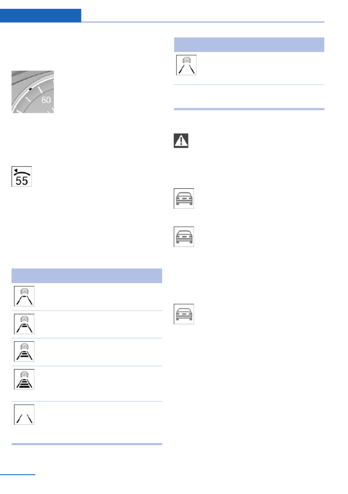
Displays in the instrument cluster
Desired speed
▷The marking lights up green:
the system is active.
▷The marking lights up or‐
ange: the system has been
interrupted.
▷The marking does not light up: the system
is switched off.
Brief status display
Selected desired speed.
If --- appears briefly on the display for Check
Control messages, it is possible that the sys‐
tem requirements for operation are currently
not met.
Distance to vehicle ahead of you
The selected distance to the vehicle driving
ahead of you is shown.
Distance display
Distance 1
Distance 2
Distance 3
Distance 4
This value is set after the system is
switched on.
The system has been interrupted or
distance control is deactivated be‐
cause the accelerator pedal is being
pressed; a vehicle was not detected.
Distance display
Distance control is deactivated be‐
cause the accelerator pedal is being
pressed; a vehicle was detected.
Rolling bars: the detected vehicle has driven
away.
Indicator/warning lamps
Personal responsibility
The indicator and warning lamps do not
relieve the driver of the responsibility to adapt
his or her desired driving speed and style to
the traffic conditions.◀
The vehicle symbol lights up orange:
A vehicle has been detected ahead of
you.
The vehicle symbol flashes orange:
The conditions are not adequate for
operating the system.
The system was deactivated but applies the
brakes until you actively resume control by
pressing on the brake pedal or accelerator
pedal.
The vehicle symbol flashes red and an
acoustic signal sounds:
You are requested to intervene by
braking or making an evasive maneuver.
System limits
Speed range
Best results are achieved when using the sys‐
tem on well-developed roads and highways.
The system is functional at speeds beginning
at approx. 20 mph/30 km/h.
The maximum speed that can be set depends
on the vehicle.
The system can also be activated when sta‐
tionary.
Controls Driving comfort
124 Online Edition for Part no. 01 40 2 925 793 - II/14

Climate control functions in detail
Manual air distribution
Turn the wheel to select the de‐
sired program or the desired in‐
termediate setting.
▷ Windows.
▷ Upper body region.
▷ Windows, upper body region, and foot‐
well.
▷ Footwell.
Defrosting windows and removing
condensation
Direct the air distribution toward windows, in‐
crease the air flow and temperature, and, if
necessary, use the cooling function.
Rear window defroster
Press the button.
The rear window defroster switches
off automatically after a certain period of time.
Air flow, manual
Press the left or right side of the but‐
ton: decrease or increase air flow.
The air flow of the air conditioner may be re‐
duced automatically to save battery power.
AUTO program
Press the button.
Air flow, air distribution, and tempera‐
ture are controlled automatically.
Depending on the selected temperature and
outside influences, the air is directed to the
windshield, side windows, upper body, and
into the footwell.
The cooling function, refer to page , is143
switched on automatically with the AUTO pro‐
gram.
Temperature
Turn the wheel to set the de‐
sired temperature.
The automatic climate control reaches this
temperature as quickly as possible, if neces‐
sary by increasing the cooling or heating out‐
put, and then keeps it constant.
Avoid rapidly switching between different tem‐
perature settings. Otherwise, the automatic cli‐
mate control will not have sufficient time to ad‐
just the set temperature.
Cooling function
The passenger compartment can only be
cooled with the engine running.
Press the button.
The air is cooled and dehumidified
and, depending on the temperature setting,
warmed again.
Depending on the weather, the windshield may
fog up briefly when the engine is started.
The cooling function is switched on automati‐
cally with the AUTO program.
When using the automatic climate control,
condensation water, refer to page , devel‐170
ops that exits underneath the vehicle.
Recirculated-air mode
You can respond to unpleasant odors or pollu‐
tants in the immediate environment by tempo‐
rarily suspending the supply of outside air. The
system then recirculates the air currently
within the vehicle.
Press the button repeatedly to select
an operating mode:
Climate control Controls
143
Online Edition for Part no. 01 40 2 925 793 - II/14
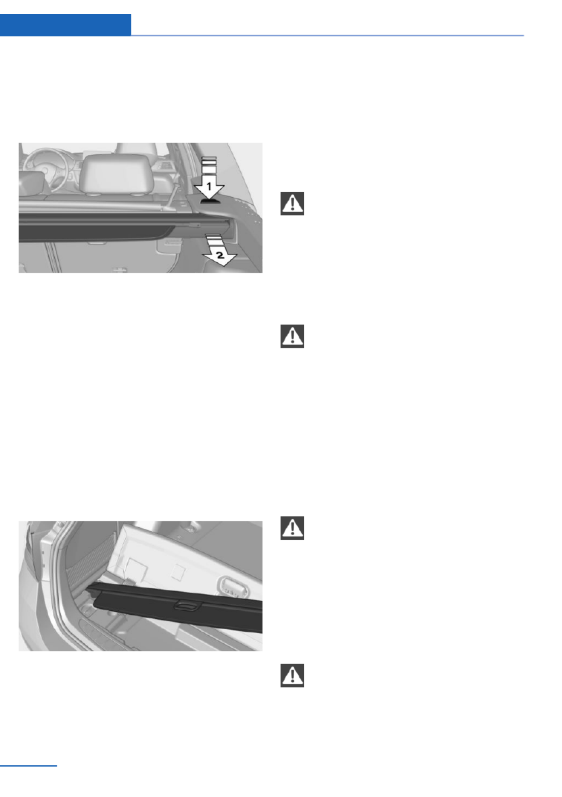
Before closing the rear window or tailgate,
push the cargo cover down until it locks into
place.
Removing
Press the release button, arrow 1, and pull the
cargo cover out towards the rear, arrow 2.
Installing
Slide the cargo cover in until it engages on
both sides with an audible click.
Stowing
If the cargo cover is not needed, it can be
stowed under the narrow cargo floor cover.
1. Fold up the narrow cargo floor cover.
2. Insert the left side of the cargo cover and
slide it to the left. Then insert the right
side.
Enlarging the cargo area
General information
The cargo area can be enlarged by folding
down the rear seat backrest.
The rear seat backrest is divided into two parts
at a ratio of 60 to 40.
If equipped with through-loading system: the
rear seat backrest is divided in the ratio 40–20–
40. The sides and the middle section can be
folded down separately.
Hints
Danger of pinching
Before folding down the rear seat back‐
rests, ensure that the area of movement of the
backrests is clear. In particular, ensure that no
one is located in or reaches into the area of
movement of the rear seat backrests when the
middle section is folded down. Otherwise, in‐
jury or damage may result.◀
Ensuring the stability of the child seat
When installing child restraint fixing sys‐
tems, make sure that the child seat is securely
fastened to the backrest of the seat. The angle
of the backrest may need to be adjusted and,
where necessary, the headrest height may also
need to be adjusted, or if possible removed.
Make sure that all backrests are securely
locked. Otherwise, the stability of the child
seat is limited, and there is an increased risk of
injury because of unexpected movement of the
rear seat backrest.◀
Ensure that the lock is securely engaged
When folding back the backrest, make
sure that it securely locks in place. When this
happens the red warning field on the seat dis‐
appears. If the backrest is not properly en‐
gaged, transported cargo could enter the pas‐
senger compartment during braking or evasive
maneuvers and endanger the vehicle occu‐
pants.◀
Using the middle safety belt
If the middle safety belt in the rear is
used, the larger side of the backrest must be
locked. Otherwise, the safety belt will not have
a restraining effect.◀
Controls Interior equipment
156 Online Edition for Part no. 01 40 2 925 793 - II/14
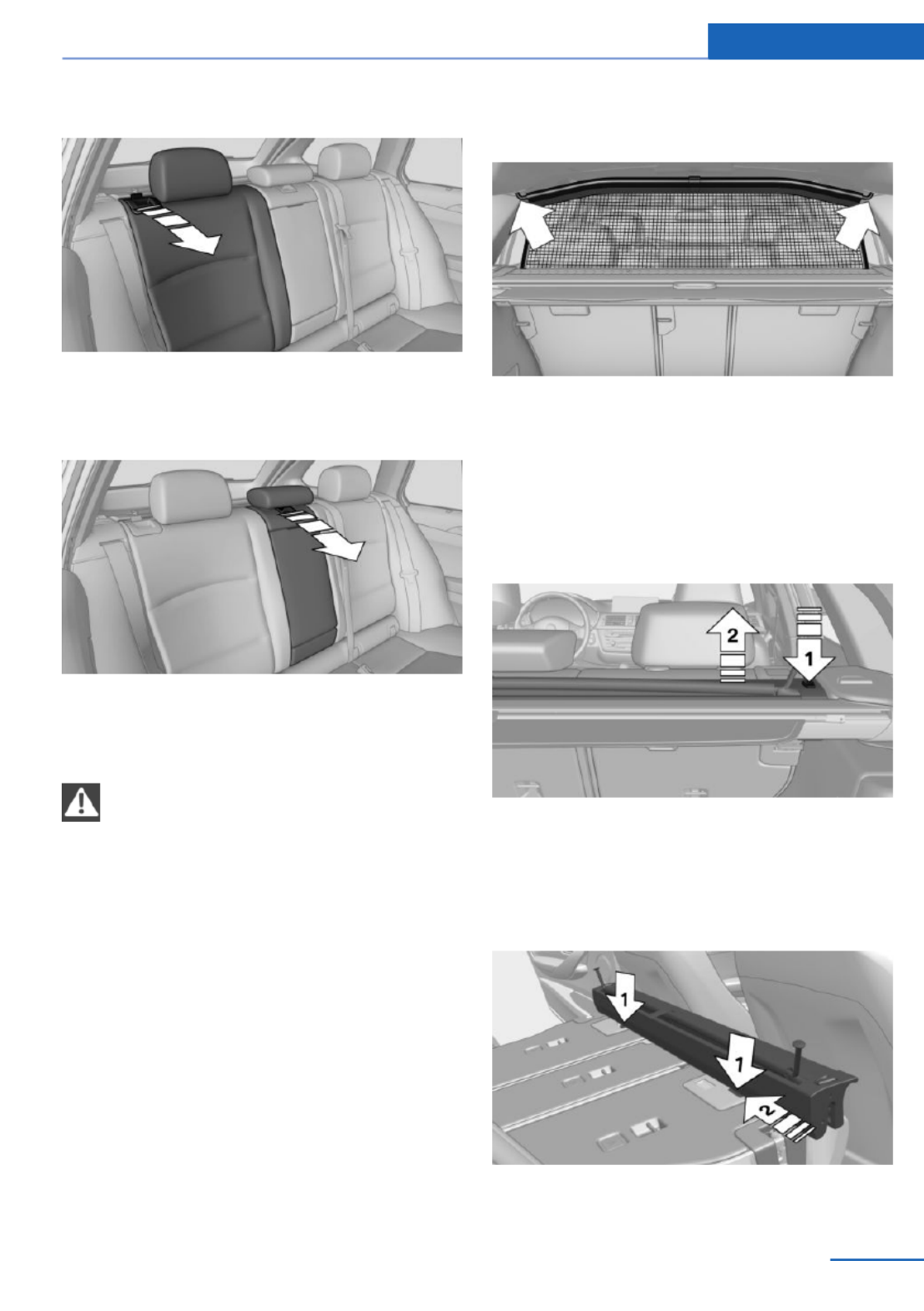
Folding down the sides
Reach into the recess and pull forward.
Folding down the middle section
Reach into the recess and pull forward.
Partition net
Do not let the partition net snap back into
place
Do not allow the partition net to snap back into
place; otherwise, there is a danger of injury and
the partition net could be damaged.◀
With a normal cargo area
1. Fold open the rear covers on the headliner.
2. Pull the partition net out of the case by the
strap.
3. Insert the bars upwards into the brackets
on either side of the headliner and push
forwards. This is best performed from the
rear seat.
If the partition net is no longer needed: pro‐
ceed in reverse order.
With an enlarged cargo area
1. Fold down the entire rear seat backrest.
2. Press the button, arrow 1, to unlock the
case on both sides.
3. Pull the case up and out of the two side
brackets, arrow 2. Make sure not to tilt it in
the process.
4. Slide the case all the way into the guides,
arrows 1, on the backs of the backrests.
Interior equipment Controls
157
Online Edition for Part no. 01 40 2 925 793 - II/14
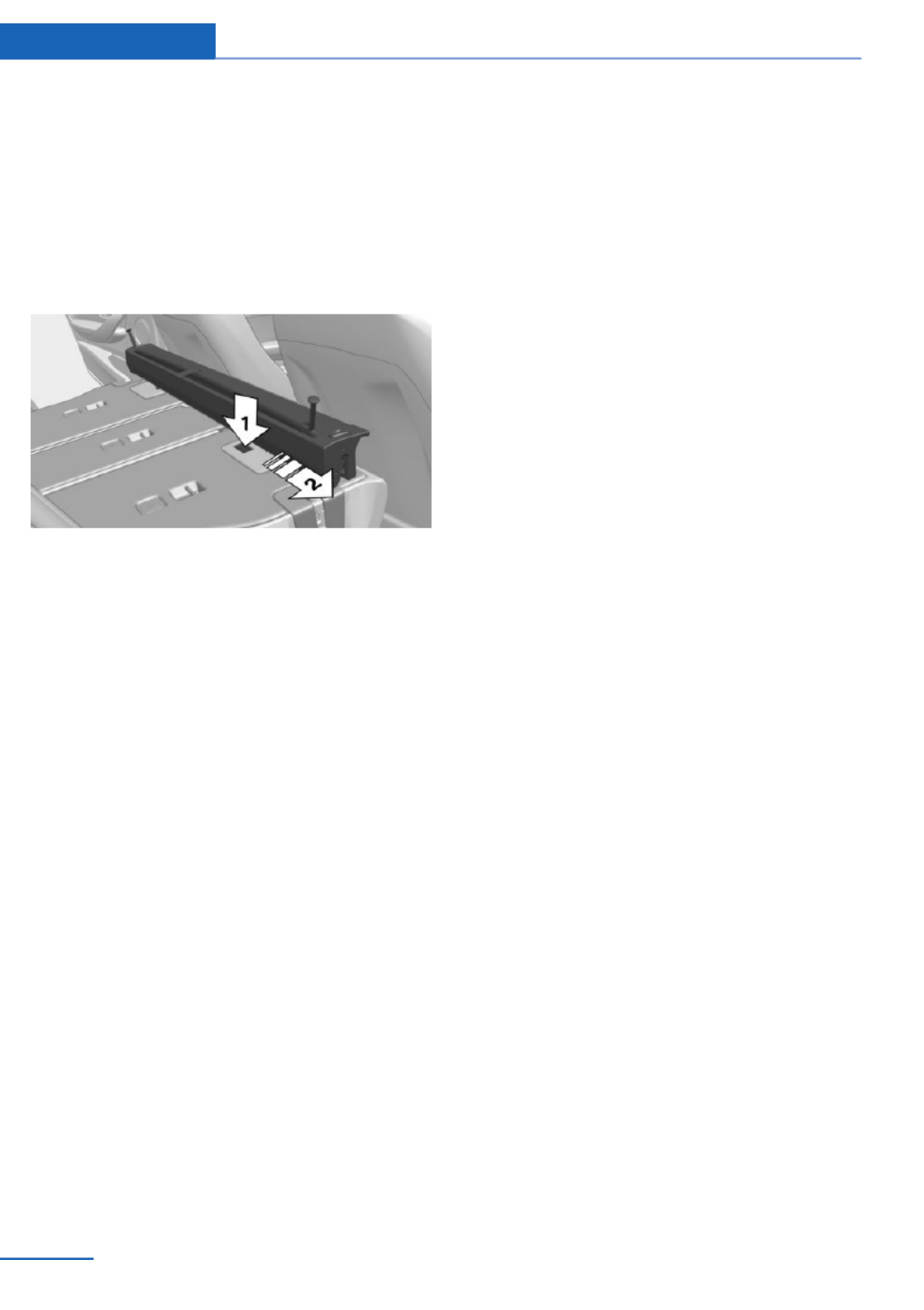
5. Fold open the front covers on the head‐
liner.
6. Quickly pull out the partition net and insert
it into the brackets as for a normal cargo
area, refer to page . If the partition net157
becomes blocked when it is pulled out, al‐
low it to retract and then pull it out quickly
again.
If the partition net is no longer needed: press
and hold button, arrow 1, and push the parti‐
tion net back, arrow 2.
Finally, slide the case into the two brackets on
the sides from above, until it engages. The red
warning fields disappear.
Controls Interior equipment
158 Online Edition for Part no. 01 40 2 925 793 - II/14

Storage compartments
Vehicle equipment
All standard, country-specific and optional
equipment that is offered in the model series is
described in this chapter. Therefore, equip‐
ment is also described that is not available in a
vehicle, e. g., because of the selected optional
equipment or country variant. This also applies
for safety-related functions and systems.
Notes
No loose objects in the passenger com‐
partment
Do not stow any objects in the passenger
compartment without securing them; other‐
wise, they may present a danger to occupants
for instance during braking and avoidance ma‐
neuvers.◀
Do not place anti-slip mats on the dash‐
board
Do not place anti-slip mats on the dashboard.
The mat materials could damage the dash‐
board.◀
Storage compartments
The following storage compartments are avail‐
able in the vehicle interior:
▷Glove compartment on the front passenger
side, refer to page .159
▷Glove compartment on the driver's side,
refer to page .160
▷Without Smoker's package: Front storage
compartment, in front of the cupholders,
refer to page .160
▷Storage compartment in the front center
armrest, refer to page .160
▷Compartments in the doors, refer to
page .160
▷Nets on the backrests of the front seats.
▷Storage compartment in the rear center
console, refer to page .161
Glove compartment
Front passenger side
Note
Close the glove compartment again im‐
mediately
Close the glove compartment immediately af‐
ter use while driving; otherwise, injury may oc‐
cur during accidents.◀
Opening
Pull the handle.
The light in the glove compartment switches
on.
The net in the glove compartment is provided
for stowing the storage tray for the cupholder,
refer to page .161
Closing
Fold cover closed.
Storage compartments Controls
159
Online Edition for Part no. 01 40 2 925 793 - II/14

Locking
The glove compartment can be locked with an
integrated key. This prevents access to the
glove compartment.
After the glove compartment is locked, the re‐
mote control can be handed over, such as at a
hotel, without the integrated key.
Driver's side
Note
Close the glove compartment again im‐
mediately
Close the glove compartment immediately af‐
ter use while driving; otherwise, injury may oc‐
cur during accidents.◀
Opening
Pull the handle.
Closing
Fold cover closed.
Front storage compartment
Raise the lid to open it.
Compartments in the doors
Do not stow any breakable objects
Do not store any breakable objects, e. g.
glass bottles, in the compartments, or there is
an increased risk of injury in the event of an ac‐
cident.◀
Center armrest
Front
A storage compartment is located in the center
armrest between the front seats.
Opening
Fold the center armrest up.
Repositioning
Center armrest can be pushed forwards or
backwards. It engages in the end positions.
Controls Storage compartments
160 Online Edition for Part no. 01 40 2 925 793 - II/14

Online Edition for Part no. 01 40 2 925 793 - II/14
Especificaciones del producto
| Marca: | BMW |
| Categoría: | Auto |
| Modelo: | 328d xDrive Sports Wagon (2014) |
¿Necesitas ayuda?
Si necesitas ayuda con BMW 328d xDrive Sports Wagon (2014) haz una pregunta a continuación y otros usuarios te responderán
Auto BMW Manuales

19 Octubre 2024
18 Octubre 2024
16 Octubre 2024
13 Octubre 2024
9 Octubre 2024
8 Octubre 2024
3 Octubre 2024
2 Octubre 2024
28 Septiembre 2024
19 Septiembre 2024
Auto Manuales
- Auto Ford
- Auto Fiat
- Auto Opel
- Auto Pioneer
- Auto Renault
- Auto Volvo
- Auto Alfa Romeo
- Auto ACME
- Auto Infiniti
- Auto Subaru
- Auto Saturn
- Auto Audi
- Auto Hyundai
- Auto GMC
- Auto Skoda
- Auto Chevrolet
- Auto Kia
- Auto Suzuki
- Auto Nissan
- Auto Mitsubishi
- Auto Peugeot
- Auto Toyota
- Auto Land Rover
- Auto Volkswagen
- Auto Chrysler
- Auto Lexus
- Auto Jaguar
- Auto Citroën
- Auto Seat
- Auto Genesis
- Auto Buick
- Auto Honda
- Auto Cadillac
- Auto Jeep
- Auto Tesla
- Auto Rover
- Auto Pontiac
- Auto Mazda
- Auto Mercedes-Benz
- Auto MG
- Auto Mini
- Auto Vauxhall
- Auto Dodge
- Auto Smart
- Auto Porsche
- Auto Maserati
- Auto Saab
- Auto Lancia
- Auto RAM
- Auto Acura
- Auto Mercury
- Auto Dacia
- Auto POLARIS
- Auto Scion
- Auto Tata
- Auto GEM
- Auto VDL
- Auto Sharper Image
- Auto Abarth
- Auto Lincoln
- Auto Mahindra
- Auto Chery
- Auto Lada
Últimos Auto Manuales
27 Octubre 2024
27 Octubre 2024
20 Octubre 2024
20 Octubre 2024
18 Octubre 2024
18 Octubre 2024
18 Octubre 2024
18 Octubre 2024
18 Octubre 2024
18 Octubre 2024