Electrolux efa9673x Manual de Usario
Electrolux
campana extractora
efa9673x
Lee a continuación 📖 el manual en español para Electrolux efa9673x (80 páginas) en la categoría campana extractora. Esta guía fue útil para 16 personas y fue valorada con 4.5 estrellas en promedio por 2 usuarios
Página 1/80
User manual
Manual de instrucciones
Manual de instruções
EFA 9673 - 90673

electrolux 3electrolux 3
electrolux 3electrolux 3
electrolux 3
GB
WW
WW
Welcome to the world of Electrelcome to the world of Electr
elcome to the world of Electrelcome to the world of Electr
elcome to the world of Electroluxolux
oluxolux
olux
Thank you for choosing a first class
product from Electrolux, which
hopefully will provide you with lots of
pleasure in the future. The Electrolux
ambition is to offer a wide variety of
quality products that make your life
more comfortable. You find some
examples on the cover in this manual.
Please take a few minutes to study this
manual so that you can take advantage
of the benefits of your new machine.
We promise that it will provide a
superior User Experience delivering
Ease-of-Mind.
Good luck!

electroluxelectrolux
electroluxelectrolux
electrolux safety warnings 55
55
5
GB
Safety warSafety war
Safety warSafety war
Safety warningsnings
ningsnings
nings
• When used as an extractor unit, the
hood must be fitted with a hose
having preferably the same diameter
as the outlet hole.
Should there already be a pipe of
diameter 125 mm that ducts to the
outside through the walls or roof, it is
possible to use the 150/125 mm
reduction flange provided. In this
case the hood will be slightly noisier.
Attention: The hose is not suppliedAttention: The hose is not supplied
Attention: The hose is not suppliedAttention: The hose is not supplied
Attention: The hose is not supplied
and must be purand must be pur
and must be purand must be pur
and must be purchased separatelychased separately
chased separatelychased separately
chased separately..
..
.
• The minimum distance between the
supporting surface for the cooking
vessels on the hob and the lowest
part of the range hood must be not
less than 50cm50cm
50cm50cm
50cm from electric cookers
and 65cm65cm
65cm65cm
65cm from gas or mixed
cookers.
If the instructions for installation for
the gas hob specify a greater
distance, this must be adhered to.
• Before any cleaning or maintenance
operation, disconnect the hood from
the mains by removing the plug or
disconnecting the home mains
switch.
• The appliance is not intended for use
by children or persons with impaired
physical, sensorial or mental faculties,
or if lacking in experience or know-
how, unless they are under
supervision or have been trained in
the use of the appliance by a person
responsible for their safety.
• Children should be monitored to
ensure that they do not play with the
appliance.
• Never use the hood without
effectively mounted grating.!
• The hood must NEVER be used as a
support surface unless specifically
indicated.
• The premises must be sufficiently
ventilated, when the kitchen hood is
used together with other gas
combustion devices or other fuels.
• The suctioned air must not be
conveyed into a conduit used for the
disposal of the fumes generated by
appliances that combust gases or
other fuels.
• The flaming of foods beneath the
hood itself is severely prohibited.
• The use of exposed flames is
detrimental to the filters and may
cause a fire risk, and must therefore
be avoided in all circumstances.
• Any frying must be done with care in
order to make sure that the oil does
not overheat and burst into flames.
• As regards the technical and safety
measures to be adopted for fume
discharging it is important to closely
follow the relations provided by the
competent authorities.
• The hood must be regularly cleaned
on both the inside and outside (AT
LEAST ONCE A MONTH, it is in any
event necessary to proceed in
accordance with the maintenance

66
66
6 electr electr
electr electr
electroluxolux
oluxolux
olux safety warnings
GB
instructions provided in this manual)..
• Failure to follow the instructions as
concerns hood and filter cleaning will
lead to the risk of fires.
• Do not use or leave the hood without
the lamp correctly mounted because
of the possible risk of electric shocks.
• We decline any responsibility for any
problems, damage or fires caused to
the appliance as the result of the
non-observance of the instructions
included in this manual.
This appliance is marked according to
the European directive 2002/96/EC on
Waste Electrical and Electronic
Equipment (WEEE).
By ensuring this product is disposed of
correctly, you will help prevent potential
negative consequences for the
environment and human health, which
could otherwise be caused by
inappropriate waste handling of this
product.
The symbol on the product, or on
the documents accompanying the
product, indicates that this appliance
may not be treated as household
waste. Instead it shall be handed over
to the applicable collection point for the
recycling of electrical and electronic
equipment.
Disposal must be carried out in
accordance with local environmental
regulations for waste disposal.
For more detailed information about
treatment, recovery and recycling of
this product, please contact your local
city office, your household waste
disposal service or the shop where you
purchased the product.

88
88
8 electr electr
electr electr
electroluxolux
oluxolux
olux control panel
GB
ContrContr
ContrContr
Control Panelol Panel
ol Panelol Panel
ol Panel
• Best results are obtained by using a low speed for normal conditions and a high
speed when odours are more concentrated.
Turn the hood on a few minutes before you start cooking.
The hood should be left on after cooking for about 15 minutes or until all the
odours have disappeared.
• The hood can also be commanded from the control panel or the remote control.
(the remote control is a special accessory and is ordered separately).
•CorrCorr
CorrCorr
Correct ventilation:ect ventilation:
ect ventilation:ect ventilation:
ect ventilation: If the cooker hood is to work correctly there must be an
under pressure in the kitchen. It is important to keep the kitchen windows
closed and have a window in an adjacent room open.
• The control switches are located on the hood’s front panel
• The cooker hood is fitted with a sensor which, in the event of extreme variations
in temperature, switches the appliance on automatically until the temperature of
the environment surrounding the hood has been significantly reduced.

electroluxelectrolux
electroluxelectrolux
electrolux control panel 99
99
9
GB
Model EFModel EF
Model EFModel EF
Model EFA 9673 - 90673A 9673 - 90673
A 9673 - 90673A 9673 - 90673
A 9673 - 90673
1.1.
1.1.
1. Light switch, ON/OFF:Light switch, ON/OFF:
Light switch, ON/OFF:Light switch, ON/OFF:
Light switch, ON/OFF:
Press briefly to switch the hob light and the "light bar" (located above the
control panel) on or off.
Press and hold the button for more than 2 seconds to switch the room lights
and the "light bar" (located above the control panel) on or off.
22
22
2. Mains switch, ON/OFFMains switch, ON/OFF
Mains switch, ON/OFFMains switch, ON/OFF
Mains switch, ON/OFF
Press for less than 1 1/2 seconds and the cooker hood goes into the "standstand
standstand
stand
byby
byby
by" position (dot “D2”“D2”
“D2”“D2”
“D2” on display is illuminated).
Press for more than 1 1/2 seconds and the cooker hood turns OFF, ALL the
controls (except the light push button) are disabled (the display is off).
Press again for more than 1 1/2 seconds to reset the cooker hood to "stand
by".
3.3.
3.3.
3. Filters saturation rFilters saturation r
Filters saturation rFilters saturation r
Filters saturation reset key: eset key:
eset key: eset key:
eset key: see the relative text on the following pages.
44
44
4. Start and choice of motor speed 1-2-3-1-2...Start and choice of motor speed 1-2-3-1-2...
Start and choice of motor speed 1-2-3-1-2...Start and choice of motor speed 1-2-3-1-2...
Start and choice of motor speed 1-2-3-1-2...
55
55
5. Intensive speed ON/OFF: Intensive speed ON/OFF:
Intensive speed ON/OFF: Intensive speed ON/OFF:
Intensive speed ON/OFF: The Intensive speed runs for 5 minutes:
If the hood is on when the Intensive speed is activated, the hood will revert to
previous speed after 5 minutes. If the hood is off when the Intensive speed is
activated, the hood will automatically turn off after 5 minutes.
The letter PP
PP
P appears on the display and the remaining time (the dot “D1”“D1”
“D1”“D1”
“D1” on
display is flashing), if interrupted an acoustic signal is heard.
66
66
6. Self-TSelf-T
Self-TSelf-T
Self-Timer ON/OFF: imer ON/OFF:
imer ON/OFF: imer ON/OFF:
imer ON/OFF: times all the speed levels (the dot “D2”“D2”
“D2”“D2”
“D2” on display is
flashing), and then the cooker hood switches off:
The self-timer is set as follows:
1st speed level 20 minutes
2nd speed level 15 minutes
3rd speed level 10 minutes
The display shows the remaining operation time, at the end of the time an
acoustic signal is heard. Depressing the push-button again exits the function.
77
77
7. DisplayDisplay
DisplayDisplay
Display
Note:Note:
Note:Note:
Note: if you have a remote control (special accessory) and the letter "bb
bb
b" appears
on the display, you should replace the battery.
Should the hood or the controls fail to operate: disconnect the power supply for at
least 5 seconds. After reconnecting the power supply wait 15 seconds and then
check that the cooker hood is now operating correctly.
D2
D1
123 456
7

1010
1010
10 electr electr
electr electr
electroluxolux
oluxolux
olux control panel
GB
GrGr
GrGr
Grease and charease and char
ease and charease and char
ease and charcoal filtercoal filter
coal filtercoal filter
coal filter
maintenance indicatormaintenance indicator
maintenance indicatormaintenance indicator
maintenance indicator
This hood is fitted with a device that
indicates when it is necessary to clean
the grease filter or the charcoal filter (if
the hood is used in the recirculation
version with a charcoal filter).
On delivery , the hood is not supplied
with a charcoal filter(EFEF
EFEF
EFA 9673 ONLA 9673 ONL
A 9673 ONLA 9673 ONL
A 9673 ONLY)Y)
Y)Y)
Y),
so the saturation indicator will be
disabled.
If the hood is to be used with a
charcoal filter, the saturation
indicator light must be enabled as
follows:
Set in "OFFOFF
OFFOFF
OFF" the hood.
Press buttons 33
33
3 and 44
44
4 simultaneously
and hold them for 3 seconds. At first
only the grease filter LED FF
FF
F will light up,
but when the charcoal filter LED CC
CC
C
lights up the saturation indicator will be
enabled.
To disable it: Press buttons 33
33
3 and 44
44
4
again simultaneously and hold
them for 3 seconds, until the charcoal
filter LED goes out.
GrGr
GrGr
Grease filter LED (F)ease filter LED (F)
ease filter LED (F)ease filter LED (F)
ease filter LED (F)
LED FF
FF
F will start to flash when it is time
to clean the grease filter.
Cleaning will be necessary after 40
working hours. Always comply with the
maintenance instructions for the grease
filter.
CharChar
CharChar
Charcoal filter LED (C)coal filter LED (C)
coal filter LED (C)coal filter LED (C)
coal filter LED (C)
The charcoal filter LED CC
CC
C will start to
flash when the charcoal filter needs to
be replaced.
This operation is necessary after
approximately 160 working hours.
Resetting the saturation indicatorResetting the saturation indicator
Resetting the saturation indicatorResetting the saturation indicator
Resetting the saturation indicator
After cleaning or replacing the filters,
press button 33
33
3 for 3 seconds until the
grease filter LED FF
FF
F or the charcoal filter
LED CC
CC
C stops flashing.

electroluxelectrolux
electroluxelectrolux
electrolux maintenance and care 1111
1111
11
GB
Maintenance and CarMaintenance and Car
Maintenance and CarMaintenance and Car
Maintenance and Caree
ee
e
••
••
•BeforBefor
BeforBefor
Before performing any maintenance operation, isolate the hood fre performing any maintenance operation, isolate the hood fr
e performing any maintenance operation, isolate the hood fre performing any maintenance operation, isolate the hood fr
e performing any maintenance operation, isolate the hood from theom the
om theom the
om the
electrical supply by switching ofelectrical supply by switching of
electrical supply by switching ofelectrical supply by switching of
electrical supply by switching off at the connector and rf at the connector and r
f at the connector and rf at the connector and r
f at the connector and removing theemoving the
emoving theemoving the
emoving the
connector fuse.connector fuse.
connector fuse.connector fuse.
connector fuse.
Or if the appliance has been connected thrOr if the appliance has been connected thr
Or if the appliance has been connected thrOr if the appliance has been connected thr
Or if the appliance has been connected through a plug and socket, then theough a plug and socket, then the
ough a plug and socket, then theough a plug and socket, then the
ough a plug and socket, then the
plug must be rplug must be r
plug must be rplug must be r
plug must be removed fremoved fr
emoved fremoved fr
emoved from the socket.om the socket.
om the socket.om the socket.
om the socket.
Air suction panelsAir suction panels
Air suction panelsAir suction panels
Air suction panels
Remove the perimeter air suction
panels to access the grease filters.
The perimeter air suction panels are
attached to the cooker hood by a
series of pinspins
pinspins
pins and coupling springscoupling springs
coupling springscoupling springs
coupling springs;
pull them outwards and detach them
from the fastening cablefastening cable
fastening cablefastening cable
fastening cable.
Clean the perimeter air suction panels
as often as the grease filters (for more
information about gentle cleaning
methods, read the paragraph
“Cleaning” in the pages that follow).
When refitting the perimeter air suction
panels, ALWAYS reattach the fastening
cables.
Make sure the panels are attached to
the cooker hood properly (snap-
fastened).
x 4

1212
1212
12 electr electr
electr electr
electroluxolux
oluxolux
olux maintenance and care
GB
Metal grMetal gr
Metal grMetal gr
Metal grease filterease filter
ease filterease filter
ease filter
• The purpose of the grease filters is to
absorb grease particles which form
during cooking and it mustmust
mustmust
must always be
used, either in the external extraction
or internal re-circulation function.
Attention: the metal grease filters
must be removed and washed, either
by hand or in the dishwasher, every
four weeks.
Removing the metal grRemoving the metal gr
Removing the metal grRemoving the metal gr
Removing the metal grease filterease filter
ease filterease filter
ease filter
• Use the spring handle and remove
the filter downward.
Hand washingHand washing
Hand washingHand washing
Hand washing
Soak grease filters for about one hour
in hot water with a grease-loosening
cleaner, then rinse off thoroughly with
hot water. Repeat the process if
necessary. Refit the grease filters
when they are dry.
DishwasherDishwasher
DishwasherDishwasher
Dishwasher
Place grease filters in the dishwasher.
Select most powerful washing
programme and highest temperature,
at least 65°C. Repeat the process.
Refit the grease filters when they are
dry.
When washing the metal grease filter
in the dishwasher a slight
discolouration of the filter can occur,
this does not have any impact on its
performance.
• Clean the inner housing using a hand
hot solution only(never use caustic
detergents, abrasive powders or
brushes).

electroluxelectrolux
electroluxelectrolux
electrolux maintenance and care 1313
1313
13
GB
CharChar
CharChar
Charcoal filtercoal filter
coal filtercoal filter
coal filter
• The charcoal filter should only be
used if you want to use the hood in
recirculation mode.
• To do this you will need an original
charcoal filter (available from your
local Service Force Centre).
•Cleaning/rCleaning/r
Cleaning/rCleaning/r
Cleaning/replacing the chareplacing the char
eplacing the chareplacing the char
eplacing the charcoal filtercoal filter
coal filtercoal filter
coal filter
Unlike other charcoal filters, the
LONGLIFE charcoal filter can be
cleaned and reactivated.
With normal use the filter should be
cleaned every second month (when
using the hood 2.5 hours per day,on
avarage). The best way to clean the
filter is in the dishwasher. Use normal
detergent and choose the highest
temperature (65º C). Wash the filter
separately so that no food parts gets
stuck on the filter and later causes bad
odours. To reactivate the charcoal, the
filter should be dried in an oven for 10
minutes with a maximum temperature
of 100º C.
After approximately three years of use,
the charcoal filter should be replaced
with a new one, as the odour reduction
capacity will be reduced.
•FittingFitting
FittingFitting
Fitting
Position the carbon filter inside the
hood to cover the protection grill of
the motor.
Fix the filter with 2 lateral knobs.
•TT
TT
To ro r
o ro r
o removeemove
emoveemove
emove proceed in the reverse
order.
• Always specify the hood model code
number and serial number when
ordering replacement filters. This
information is shown on the rating
plate located on the inside of the unit.
• The charcoal filter can be ordered
from your local Service Force Centre.

1414
1414
14 electr electr
electr electr
electroluxolux
oluxolux
olux maintenance and care
GB
WW
WW
Warar
arar
arningning
ningning
ning
• Failure to observe the instructions on
cleaning the unit and changing the
filters will cause a fire hazard. You are
therefore strongly recommended to
follow these instructions.
• The manufacturer declines all
responsibility for any damage to the
motor or any fire damage linked to
inappropriate maintenance or failure
to observe the above safety
recommendations.
Changing the light bulb(s)Changing the light bulb(s)
Changing the light bulb(s)Changing the light bulb(s)
Changing the light bulb(s)
•Disconnect the cooker hood frDisconnect the cooker hood fr
Disconnect the cooker hood frDisconnect the cooker hood fr
Disconnect the cooker hood fromom
omom
om
the mains supplythe mains supply
the mains supplythe mains supply
the mains supply..
..
.
••
••
•Prior to touching the light bulbsPrior to touching the light bulbs
Prior to touching the light bulbsPrior to touching the light bulbs
Prior to touching the light bulbs
ensurensur
ensurensur
ensure they are they ar
e they are they ar
e they are cooled down.e cooled down.
e cooled down.e cooled down.
e cooled down.
• Replace the old bulb with a new one
of the same type.
• If the light does not come on, make
sure the bulb has been inserted in
correctly before contacting your local
Service Force Centre.
20W max20W max
20W max20W max
20W max
GU4 - 12 V - Ø 35mm - 30° - Dichroic

electroluxelectrolux
electroluxelectrolux
electrolux maintenance and care 1515
1515
15
GB
Cleaning the hoodCleaning the hood
Cleaning the hoodCleaning the hood
Cleaning the hood
• Clean the outside of the hood using a
damp cloth and a solution of water
and mild washing up liquid.
• Never use corrosive, abrasive or
flammable cleaning products or
products containing bleach.
• Never insert pointed objects in the
motor’s protective grid.
• Only ever clean the switch panel and
filter grill using a damp cloth and mild
washing up liquid.
• Clean all the plastic parts with a soft
cloth soaked in warm water and
neutral soap.
• It is extremely important to clean the
unit and change the filters at the
recommended intervals. Failure to do
so will cause grease deposits to build
up that could constitute a fire hazard.

1616
1616
16 electr electr
electr electr
electroluxolux
oluxolux
olux special accessories
GB
Special accessories
CharChar
CharChar
Charcoal filtercoal filter
coal filtercoal filter
coal filter Type 967
Remote contrRemote contr
Remote contrRemote contr
Remote controlol
olol
ol RM 7000
Something Not Working
If your appliance fails to work properly please carry out the following checks.
SymptomSymptom
SymptomSymptom
Symptom
The cooker hood will not start...
The cooker hood is not working
The cooker hood has switched off
during operation...
SolutionSolution
SolutionSolution
Solution
Check that: Check that:
Check that: Check that:
Check that: The hood is connected
to the electricity supply.
Check that a fan speed has been
selected.
Check that: Check that:
Check that: Check that:
Check that: The fan speed is set high
enough for the task.
The grease filters are clean.
The kitchen is adequately vented to
allow the entry of fresh air.
If set up for recirculation, check that
the charcoal filter is still effective.
If set up for extraction, check that the
ducting and outlets are not blocked.
The safety cut-out device has been
tripped. Turn off the hob and then wait
for the device to reset. If the hood has
been installed below the heights
indicated in the installation instructions
the motor will cut-out frequently which
will damage the hood.
If after all these checks, the problem persists, contact your local Service Centre,
quoting the model and serial number.
Please note that it will be necessary to provide proof of purchase for any in-
guarantee service calls.
In-guarantee customers should ensure that the above checks have been made as
the engineer will make a charge if the fault is not a mechanical or electrical
breakdown.

electroluxelectrolux
electroluxelectrolux
electrolux installation 1919
1919
19
GB
InstallationInstallation
InstallationInstallation
Installation
Make surMake sur
Make surMake sur
Make sure that the cooker hood is disconnected fre that the cooker hood is disconnected fr
e that the cooker hood is disconnected fre that the cooker hood is disconnected fr
e that the cooker hood is disconnected from the power supply beforom the power supply befor
om the power supply beforom the power supply befor
om the power supply beforee
ee
e
carrying out the installation.carrying out the installation.
carrying out the installation.carrying out the installation.
carrying out the installation.
The cooker hood comes with fixing plugs which are suitable for use with most
walls/ceilings. Nevertheless, you should ask a qualified technician to assess the
suitability of the materials in accordance with the type of wall/ceiling. The wall/
ceiling must be sufficiently sturdy so as to support the weight of the cooker hood.
Remove the perimeter air suction panels and the grease filters.
BeforBefor
BeforBefor
Before installing the pre installing the pr
e installing the pre installing the pr
e installing the product:oduct:
oduct:oduct:
oduct:
The perforated frame for the cooker hood is supplied prior to installation in parts.
The main parts making up the perforated frame are as follows:
• the upper perforated frame AA
AA
A (x1)
• the perforated frame extension brackets BB
BB
B (x4)
• the reinforcement brackets CC
CC
C (x3), of which:
2 are for use on the upper part C1 - C1 -
C1 - C1 -
C1 - 1 of which is pre-assembled
1 is for use on the lower part C2C2
C2C2
C2
Description of the upper perforated frame A:Description of the upper perforated frame A:
Description of the upper perforated frame A:Description of the upper perforated frame A:
Description of the upper perforated frame A: Point at which the perforated
frame is fixed/hooked to the
ceiling
Fixing points for extension
brackets BB
BB
B
Fixing points for the 2
reinforcement brackets C1C1
C1C1
C1
Reinforcement brackets C1C1
C1C1
C1

2020
2020
20 electr electr
electr electr
electroluxolux
oluxolux
olux installation
GB
Description of the rDescription of the r
Description of the rDescription of the r
Description of the reinforeinfor
einforeinfor
einforcement brackets C1 and C2cement brackets C1 and C2
cement brackets C1 and C2cement brackets C1 and C2
cement brackets C1 and C2
reinforcement brackets C1C1
C1C1
C1
(upper and intermediate)
reinforcement bracket
C2C2
C2C2
C2 (lower)
Points at which they
are fixed to the upper
frame
Fixing points for
the lower
reinforcement
bracket C2C2
C2C2
C2
Points at which
the bracket is fixed
to the cooker
hood
Description of the extension brackets B:Description of the extension brackets B:
Description of the extension brackets B:Description of the extension brackets B:
Description of the extension brackets B:

electroluxelectrolux
electroluxelectrolux
electrolux installation 2121
2121
21
GB
L
E
E (mm)= L- 355
PrPr
PrPr
Preparing the structural supporteparing the structural support
eparing the structural supporteparing the structural support
eparing the structural support
Before assembling the perforated
frame, calculate the extension it
requires.
Use the formula given in the adjacent
diagram to help you.
Make a note of measurement EE
EE
E in this
booklet; it will serve as a reference
when you are calculating the length of
the exhaust tube.
Measurement LL
LL
L should respect the
minimum permitted distances from the
hob, as indicated in the paragraph
entitled “Safety warnings – for the
installer”.
• Fit the extension brackets BB
BB
B to the
perforated frame using 4 screws for
each, so that the perforated frame
can be extended to the calculated
length EE
EE
E.

2222
2222
22 electr electr
electr electr
electroluxolux
oluxolux
olux installation
GB
For perforated frame extensions (please refer to measurement EE
EE
E calculated
previously):
-smaller than 690 mm: smaller than 690 mm:
smaller than 690 mm: smaller than 690 mm:
smaller than 690 mm: this extension requires only one bracket (C1C1
C1C1
C1); generally
this is already fixed in place.
-between 690 mm and 795 mm: between 690 mm and 795 mm:
between 690 mm and 795 mm: between 690 mm and 795 mm:
between 690 mm and 795 mm: fit both C1C1
C1C1
C1 brackets.
- greater than 800 mm: fit all available reinforcement brackets (2 x C1 + 1 x C22 x C1 + 1 x C2
2 x C1 + 1 x C22 x C1 + 1 x C2
2 x C1 + 1 x C2)
Use 8 screws to fix each reinforcement bracket in place.
Note:Note:
Note:Note:
Note: One of the two C1C1
C1C1
C1 brackets is usually already fitted when the appliance is
supplied.
C1
C1
C2
electroluxelectrolux
electroluxelectrolux
electrolux installation 2323
2323
23
GB
Installing the structural support toInstalling the structural support to
Installing the structural support toInstalling the structural support to
Installing the structural support to
the cooker hoodthe cooker hood
the cooker hoodthe cooker hood
the cooker hood
• Fix the cooker hood to the structural
support using 16 screws (4 per
bracket).
Installing the structural support toInstalling the structural support to
Installing the structural support toInstalling the structural support to
Installing the structural support to
the ceilingthe ceiling
the ceilingthe ceiling
the ceiling
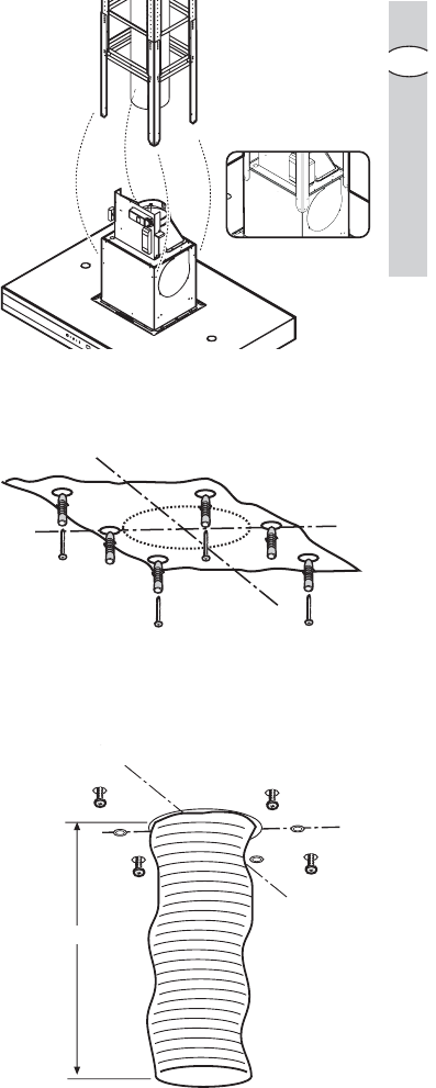
• Place the template on the ceiling
directly above the hob (the centre
and sides of the template should be
aligned with the centre and sides of
the hob).
Note:Note:
Note:Note:
Note: The side displaying the text
“FRONT” corresponds to the side
which will house the control panel
once installation is complete.
• Make the holes as indicated on the
template (6 holes for 6 screw
anchors) and partially tighten 4
screws into the screw anchors in the
corners (leave approximately 1 cm
between the head of the screw and
the ceiling).
• Prepare the electrical connection.
•Ducted version only:Ducted version only:
Ducted version only:Ducted version only:
Ducted version only: Install an
exhaust tube long enough to reach
the outlet ring located above the
cooker hood.
The tube should be fitted to the
ceiling as an exhaust system to expel
fumes outside; the visible part should
be 180 mm shorter than the
structural support (please refer to
measurement EE
EE
E calculated
previously).
FRONT
6 x Ø 10 + 4 x Ø 6x70
SX DX
FRONT
E (mm)-180

2424
2424
24 electr electr
electr electr
electroluxolux
oluxolux
olux installation
GB
• Install the structure to the ceiling,
onto the 4 pre-tightened screws and
then screw them in firmly.
• Fix it in place using 2 screws.
•For the rFor the r
For the rFor the r
For the recirecir
ecirecir
ecirculation mode only:culation mode only:
culation mode only:culation mode only:
culation mode only:
assemble the three parts of the
deflector (central part + 2 extensions)
using 2 screws so that once
assembled, the deflector is the same
width as the structural support.
Fasten the deflector inside the
structural support using 4 screws.
Fit an exhaust tube to the deflector
connection ring. The tube must be
300 mm shorter in length than the
structural support (please refer to
measurement EE
EE
E calculated
previously).
• Connect the exhaust tube to the
connection ring above the cooker
hood.
• Carry out the necessary electrical
connection.
X 4!
2 x
Ø6 x 70
F

electroluxelectrolux
electroluxelectrolux
electrolux installation 2525
2525
25
GB
Installing the fluesInstalling the flues
Installing the fluesInstalling the flues
Installing the flues
• Fix the nuts in place with the
couplings both on the upper internal
sections of the flues (P+Q) and on the
lower back section of the flues (R).
• Fix the two upper flue sections (P+Q)
directly onto the structural support of
the cooker hood according to the
assembly diagram (see adjacent
figure).
For the filter version, the upper
sections must be fitted so that the air
recirculation slots are facing upwards.
If you wish to use the cooker hood as
a ducted model, for aesthetic
purposes, the upper flue sections can
be turned upside down to hide the
slots when the lower flue sections are
installed.
P x 3
R x 6
Q x 3
PQ
R
S
S x 0

2626
2626
26 electr electr
electr electr
electroluxolux
oluxolux
olux installation
GB
Fix the section in place using 6
screws (3 per side).
• Lift the flues and fix them onto the
structural support using 2 screws (1
per side).
• Install the lower back section of the
flue (R) by resting it on top of the
cooker hood in the correct position
(widen it slightly to allow for an easy
fit onto the upper flue).
• Install the lower front section of the
flue (S) and widen it slightly to allow
for an easy fit onto the upper section.
Fix the section in place using 6
screws (3 per side).
P
QR
S
P
Q
R
S

electroluxelectrolux
electroluxelectrolux
electrolux installation 2727
2727
27
GB
• Cover the fixing points with 4
casings:
The two lower parts may be hooked
on, however the upper parts must be
cut to size and snapped into place.
• Fix the lower flues in place from inside
the cooker hood using 2 screws.
Reattach the grease filters and the
perimeter air suction panels.
Connect the hood to the mains
electricity (wait about 15 seconds, the
time needed to calibrate the electronic
device that controls the functioning of
the hood), and check, finally, that it is
functioning well.
Only for EFOnly for EF
Only for EFOnly for EF
Only for EFA 90673:A 90673:
A 90673:A 90673:
A 90673:
The charcoal filter saturation indicator is
disabled.
To enable it please read page 10.
XX

electroluxelectrolux
electroluxelectrolux
electrolux indice 2929
2929
29
E
IndiceIndice
IndiceIndice
Indice
Recomendaciones de seguridad...... 30
Descripción del aparato ................... 32
Funcionamiento de la campana ....... 33
Mantenimiento y cuidado................. 36
Accesorios especiales ..................... 41
Instalación ....................................... 42
En este manual se utiliza los siguientes simbolos :
Informaciones importantes que corresponden a la seguridad personal e
informaciones para evitar daños al aparato.
Informaciones generales y consejos :
Informaciones sobre la conservación ambiental.

3030
3030
30 electr electr
electr electr
electroluxolux
oluxolux
olux recomendaciones de seguridad
E
Recomendaciones de seguridadRecomendaciones de seguridad
Recomendaciones de seguridadRecomendaciones de seguridad
Recomendaciones de seguridad
mentales y sin experiencia y
conocientos a menos que no sea
bajo control de profesionales para el
uso del aparato, una persona
responsable para vuestra seguridad.
• Los niños deben ser controlados
para evitar que jueguen con el
aparato.
• Nunca utilizar la campana sin la
parrilla correctamente montada!
• La campana no va Nunca utilizada
como plano de apoyo solo si es
expresamente indicado.
• El ambiente debe poseer suficiente
ventilación, cuando la campana de
cocina es utilizada conjuntamente
con otros aparatos a gas u otros
combustibles.
• El aire aspirado no debe ser
mezclado en un conducto para
descarga de humo producidos por
aparatos a gas u otros combustibles.
• Es prohibido cocinar alimentos con
llama alta por debajo de la campana.
• El uso de las llamas libres puede
provocar daños a los filtros y dar
lugar a incendios, por lo tanto evitar
en cada caso.
• Las frituras deben ser cocinadas bajo
control para evitar que el aceite
recalentado prenda fuego.
• En cuanto a las medidas técnicas y
de seguridad adoptar para la
descarga de humo atenerse
estrictamente a las reglas de las
autoridades locales.
• En caso de funcionamiento de
aspiración, salida libre, el tubo de
descarga debe tener el mismo
diámetro del anillo de conexión.
Si en la pared o en el techo ya existe
un tubo de aspiración del aire con un
diámetro igual a 125 mm, se puede
utilizar el manguito de reducción 150/
125 mm. El funcionamiento del
equipo será un poco más ruidoso.
Atención: tubo no suministrado, seAtención: tubo no suministrado, se
Atención: tubo no suministrado, seAtención: tubo no suministrado, se
Atención: tubo no suministrado, se
puede adquirir separadamente.puede adquirir separadamente.
puede adquirir separadamente.puede adquirir separadamente.
puede adquirir separadamente.
• La distancia mínima entre la superfi-
cie de cocción y la parte más baja de
la campana no debe ser inferior a
50cm50cm
50cm50cm
50cm en el caso de cocinas
electricas y de 65cm65cm
65cm65cm
65cm en el caso de
cocinas a gas o mixtas.
Si las instrucciones para la
instalación del dispositivo para
cocinar con gas especifican una
distancia mayor, hay que tenerlo en
consideración.
••
••
•Atención!Atención!
Atención!Atención!
Atención!No conectar el aparato a la
red eléctrica hasta que la instalación
fue completada.
• Antes de cualquier operación de
limpieza o mantenimento,
desenchufar la campana o el
interruptor general de la casa.
• El aparato no está destinado para el
uso por parte de los niños o
personas con problemas fisicos o

electroluxelectrolux
electroluxelectrolux
electrolux recomendaciones de seguridad 3131
3131
31
E
• La campana se debe limpiar siempre
internamente y externamente (COMO
MINIMO UNA VEZ AL MES,
respetando las reglas indicadas en
este manual)
• No efectuar los consejos de limpieza
de la campana y el cambio de los
filtros puede provocar incendios.
• No utilice o deje la campana sin las
lámparas correctamente montadas,
debido a riesgos de cortocircuito.
• Se declina todo tipo de
responsabilidades, daños o incendios
provocados por no leer atentamente
las instrucciones indicadas en este
manual.
Este aparato lleva el marcado CE en
conformidad con la Directiva 2002/96/
EC del Parlamento Europeo y del
Consejo sobre residuos de aparatos
eléctricos y electrónicos (RAEE).
La correcta eliminación de este
producto evita consecuencias
negativas para el medioambiente y la
salud.
El símbolo en el producto o en los
documentos que se incluyen con el
producto, indica que no se puede
tratar como residuo doméstico. Es
necesario entregarlo en un punto de
recogida para reciclar aparatos
eléctricos y electrónicos.
Deséchelo con arreglo a las normas
medioambientales para eliminación de
residuos.
Para obtener información más
detallada sobre el tratamiento,
recuperación y reciclaje de este
producto, póngase en contacto con el
ayuntamiento, con el servicio de
eliminación de residuos urbanos o la
tienda donde adquirió el producto.

3232
3232
32 electr electr
electr electr
electroluxolux
oluxolux
olux descripción del aparato
E
Descripción del aparatoDescripción del aparato
Descripción del aparatoDescripción del aparato
Descripción del aparato
• La campana se entrega en modo
extractor, pudiendo utilizarla también
en modo de recirculación, instalando
para ello un filtro de carbón activado
(accesorio especial).
• Para esta función, es necesario un
filtro de carbón activo original (véase
el párrafo «Accesorios especiales»).
•Ùnicamente por EFÙnicamente por EF
Ùnicamente por EFÙnicamente por EF
Ùnicamente por EFA 90673:A 90673:
A 90673:A 90673:
A 90673: esta
campana incluye 1 filtro de carbón.
Funcionamiento extractorFuncionamiento extractor
Funcionamiento extractorFuncionamiento extractor
Funcionamiento extractor
• El aire se extrae al exterior mediante
un tubo conectado al anillo de
conexión..
..
.
• Para un mejor rendimiento , el tubo
tiene que tener el mismo diámetro
que el orificio de salida.
Si en la pared o en el techo ya existe
un tubo de aspiración del aire con un
diámetro igual a 125 mm, se puede
utilizar el manguito de reducción 150/
125 mm. El funcionamiento del
equipo será un poco más ruidoso.
Funcionamiento de rFuncionamiento de r
Funcionamiento de rFuncionamiento de r
Funcionamiento de recirecir
ecirecir
ecirculaciónculación
culaciónculación
culación
• El filtro de carbón filtra el aire que
pasa de nuevo a la cocina a través
de la rejilla superior de la chimenea
de aspiración.
• Para esta función, es necesario un
filtro de carbón activo original (véase
el párrafo «Accesorios especiales»).
anillo de conexiónanillo de conexión
anillo de conexiónanillo de conexión
anillo de conexión

3434
3434
34 electr electr
electr electr
electroluxolux
oluxolux
olux funcionamiento de la campana
E
Modelo EFModelo EF
Modelo EFModelo EF
Modelo EFA 9673 - 90673A 9673 - 90673
A 9673 - 90673A 9673 - 90673
A 9673 - 90673
1.1.
1.1.
1. Boton ON/OFF luz:Boton ON/OFF luz:
Boton ON/OFF luz:Boton ON/OFF luz:
Boton ON/OFF luz:
Presione brevemente para encender o apagar la iluminación de la campana y
la "barra luminosa" ubicada sobre el panel de mandos.
Presione el botón durante más de 2 segundos para encender o apagar las
luces de la campana y la "barra luminosa" ubicada sobre el panel de mandos.
22
22
2. Botón principalBotón principal
Botón principalBotón principal
Botón principal se enciende y se apaga la campana.
Mantenga apretado durante menos de 1,5 segundos, la campana se pone en
posición de espera (Stand byStand by
Stand byStand by
Stand by) ( el puntopunto
puntopunto
punto “D2”“D2”
“D2”“D2”
“D2” está encendido).
Mantenga apretado durante mas de 1,5 segundos, la campana se apagará
(OFFOFF
OFFOFF
OFF), TODOS los controles (excepto el que enciende la luz) están
desconectados ( el display está completamente apagado).
Vuelva a apretar de nuevo durante mas de 1,5 segundos para poner de nuevo
la campana en posición de stand-by.
3.3.
3.3.
3. Botón de rBotón de r
Botón de rBotón de r
Botón de reiniciación saturación filtreiniciación saturación filtr
einiciación saturación filtreiniciación saturación filtr
einiciación saturación filtros:os:
os:os:
os: véase el texto relativo en las paginas
siguientes.
44
44
4. Arranca y selecciona la velocidad del motor 1-2-3-1-2...Arranca y selecciona la velocidad del motor 1-2-3-1-2...
Arranca y selecciona la velocidad del motor 1-2-3-1-2...Arranca y selecciona la velocidad del motor 1-2-3-1-2...
Arranca y selecciona la velocidad del motor 1-2-3-1-2...
55
55
5. Se enciende y se apaga la velocidad intensiva. Se enciende y se apaga la velocidad intensiva.
Se enciende y se apaga la velocidad intensiva. Se enciende y se apaga la velocidad intensiva.
Se enciende y se apaga la velocidad intensiva. La velocidad intensiva
funciona durante 5 minutos: Si la campana está encendida cuando la
velocidad intensiva está activada, la campana transcurridos 5 minutos vuelve a
la velocidad inicial.
Si la campana está apagada cuando la velocidad intensiva está activada, la
campana transcurridos 5 minutos se apaga automáticameante.
La letra PP
PP
P aparece en el display y el tiempo que queda ( el puntopunto
puntopunto
punto “D1”“D1”
“D1”“D1”
“D1”
parpadea), hasta el final el sistema emite una señal acústica.
66
66
6. TT
TT
Timer ON/OFF: imer ON/OFF:
imer ON/OFF: imer ON/OFF:
imer ON/OFF: mide el tiempo de las velocidades ( el puntopunto
puntopunto
punto “D2”“D2”
“D2”“D2”
“D2” parpadea)y
entonces la campana se apaga:
1° velocidad 20 minutos
2° velocidad 15 minutos
3° velocidad 10 minutos
El display muestra el tiempo que queda para el final, el sistema emite una
señal acustica. Manteniendo apretado el botón de nuevo finaliza la función.
77
77
7. DisplayDisplay
DisplayDisplay
Display
Nota:Nota:
Nota:Nota:
Nota: si posee un telemando (accesorio especial) y en la pantalla aparece la letra
"bb
bb
b", sustituya la batería.
Si la campana o los demás componentes no funcionaran bien: desconecte la
corriente electrica durante al menos 5 segundos, despues vuelva a encender la
campana. Espere al menos 15 segundos para comprobar que la campana está
funcionando correctamente.
D2
D1
123 456
7

electroluxelectrolux
electroluxelectrolux
electrolux funcionamiento de la campana 3535
3535
35
E
Dispositivo de contrDispositivo de contr
Dispositivo de contrDispositivo de contr
Dispositivo de control para el filtrol para el filtr
ol para el filtrol para el filtr
ol para el filtroo
oo
o
antigrasa y para el filtrantigrasa y para el filtr
antigrasa y para el filtrantigrasa y para el filtr
antigrasa y para el filtro al carbóno al carbón
o al carbóno al carbón
o al carbón
activo.activo.
activo.activo.
activo.
Esta campana posee un dispositivo
que avisa cuando hay que limpiar el
filtro antigrasa o cuando hay que
cambiar el filtro al carbón activo [para la
función de recirculación con el filtro al
carbón activo]
Esta campana viene de fábrica sin el
filtro al carbón activo (Ùnicamente por(Ùnicamente por
(Ùnicamente por(Ùnicamente por
(Ùnicamente por
EFEF
EFEF
EFA 9673)A 9673)
A 9673)A 9673)
A 9673), por lo tanto el aviso de
saturación no está activo.
Si la campana viene con el filtro al
carbón activo se puede poner en
funcionamiento esta función que avisa
de la saturación de la siguiente manera:
Coloque la campana en «OFFOFF
OFFOFF
OFF».
hay que pulsar a la vez los botones 33
33
3 y
44
44
4 durante 3 segundos.
Al principio se ilumina solamente el
PILOTO FF
FF
F que avisa del filtro antigrasa,
e inmediatamente despues se
enciende tambien el PILOTO CC
CC
C que
avisa del filtro al carbón activo y de esa
manera se pone en marcha la función
que avisa de la saturación.
Para desactivarla pulse otra vez los
botones 33
33
3 y 44
44
4 a la vez hasta que se
ilumine el PILOTO CC
CC
C que avisa del filtro
al carbón.
PILOTO [F] que avisa del filtrPILOTO [F] que avisa del filtr
PILOTO [F] que avisa del filtrPILOTO [F] que avisa del filtr
PILOTO [F] que avisa del filtroo
oo
o
antigrasa.antigrasa.
antigrasa.antigrasa.
antigrasa.
El PILOTO FF
FF
F se ilumina cuando hay que
limpiar el filtro antigrasa. Esto se
produce cuando hayan pasado
aproximadamente 40 horas de uso.
Lea las instrucciones sobre el
mantenimiento del filtro antigrasa.
PILOTO [C] que avisa del filtrPILOTO [C] que avisa del filtr
PILOTO [C] que avisa del filtrPILOTO [C] que avisa del filtr
PILOTO [C] que avisa del filtro delo del
o delo del
o del
carbón activocarbón activo
carbón activocarbón activo
carbón activo
El PILOTO CC
CC
C se ilumina cuando hay
que limpiar el filtro del carbón activo.
Esto se produce cuando hayan pasado
160 horas de uso.
Lea las instrucciones para cambiar el
filtro al carbón.
Resetear la señal de saturaciónResetear la señal de saturación
Resetear la señal de saturaciónResetear la señal de saturación
Resetear la señal de saturación
Despues de limpiar o volver a colocar
los filtros , apriete el botón 33
33
3 durante 3
segundos hasta que el piloto del filtro
antigrasa PILOTO FF
FF
F o el piloto del filtro
al carbón activo PILOTO CC
CC
C dejen de
parpadear.

3636
3636
36 electr electr
electr electr
electroluxolux
oluxolux
olux mantenimiento y cuidado
E
Mantenimiento y cuidadoMantenimiento y cuidado
Mantenimiento y cuidadoMantenimiento y cuidado
Mantenimiento y cuidado
Antes de rAntes de r
Antes de rAntes de r
Antes de realizar cualquier operación de limpieza o mantenimiento, desconecteealizar cualquier operación de limpieza o mantenimiento, desconecte
ealizar cualquier operación de limpieza o mantenimiento, desconecteealizar cualquier operación de limpieza o mantenimiento, desconecte
ealizar cualquier operación de limpieza o mantenimiento, desconecte
la campana de la rla campana de la r
la campana de la rla campana de la r
la campana de la red eléctrica desenchufándola o desconectando el interruptored eléctrica desenchufándola o desconectando el interruptor
ed eléctrica desenchufándola o desconectando el interruptored eléctrica desenchufándola o desconectando el interruptor
ed eléctrica desenchufándola o desconectando el interruptor
general de la vivienda.general de la vivienda.
general de la vivienda.general de la vivienda.
general de la vivienda.
Paneles de aspiraciónPaneles de aspiración
Paneles de aspiraciónPaneles de aspiración
Paneles de aspiración
Para acceder a los filtros antigrasa, es
necesario extraer previamente los
paneles de aspiración perimetral.
Los paneles de aspiración perimetral
están fijados a la campana mediante un
sistema de perper
perper
pernosnos
nosnos
nos y muelles demuelles de
muelles demuelles de
muelles de
engancheenganche
engancheenganche
enganche: es suficiente tirar hacia
afuera con decisión y desengancharlos
del cable de rcable de r
cable de rcable de r
cable de retención.etención.
etención.etención.
etención.
Los paneles de aspiración tienen que
limpiarse con la misma frecuencia que
la de los filtros antigrasa (para la
limpieza véase el apartado “Limpieza”
en las páginas siguientes).
Al volver a colocar los paneles de
aspiración perimetral, SIEMPRE hay
que enganchar los cables de retención.
Controlar que los paneles queden
efectivamente fijados a la campana
(enganche a presión).
x 4

3838
3838
38 electr electr
electr electr
electroluxolux
oluxolux
olux mantenimiento y cuidado
E
FiltrFiltr
FiltrFiltr
Filtro de carbón activadoo de carbón activado
o de carbón activadoo de carbón activado
o de carbón activado
• El filtro de carbón activado solo se
utiliza para la función de recirculación.
• Instalar siempre un filtro de carbón
activado original. (véase el párrafo
«Accesorios especiales»).
•Limpieza\sustitución del filtrLimpieza\sustitución del filtr
Limpieza\sustitución del filtrLimpieza\sustitución del filtr
Limpieza\sustitución del filtro deo de
o deo de
o de
carbóncarbón
carbóncarbón
carbón
Al contrario de otros tipos, el filtro de
carbón, el filtro al carbón LONGLIFE
se puede limpiar y volverlo a poner en
la campana.
Se aconseja, en un uso normal,
limpiar el filtro cada dos meses. El
lavado en lavavajillas es la mejor
manera para limpiarlo.Use un deter-
gente normal y seleccione la tempe-
ratura más alta (65°C). Lave el filtro
por separado para evitar que se
peguen restos de comida y puedan
causar mal olor. Para poderlo usar
otra vez, métalo en el horno durante
10 minutos a una temperatura
máxima de 100°C.
Se aconseja cambiar el filtro al
carbón después de 3 años
aproximadamente porque la
capacidad de absorción de los olores
podría disminuir.
•MontajeMontaje
MontajeMontaje
Montaje
Posicione el filtro al carbón en el
interior de la campana en la cubierta
de la rejilla de protección del motor.
Fije el filtro con 2 pernos laterales.
•Para el desmontajePara el desmontaje
Para el desmontajePara el desmontaje
Para el desmontaje, efectuar las
operaciones anteriores en orden
inverso.
• Cuando se vaya a pedir un filtro de
recambio, indicar el modelo y el
número de producto. Estos datos
pueden leerse en la placa de
características colocada en la parte
interna del aparato.
• El filtro de carbón activado puede
solicitarse al servicio de asistencia
técnica.

electroluxelectrolux
electroluxelectrolux
electrolux mantenimiento y cuidado 3939
3939
39
E
AtenciónAtención
AtenciónAtención
Atención
• De no observarse las instrucciones
dadas para limpiar el aparato y
sustituir el filtro, puede producirse un
incendio. El fabricante recomienda
leerlas y respetarlas atentamente.
• El fabricante no se hace responsable
por los daños al motor o los incen-
dios provocados en el aparato
debido a intervenciones de manteni-
miento incorrectas o al incumplimien-
to de las normas de seguridad
proporcionadas.
Sustitución de la bombillasSustitución de la bombillas
Sustitución de la bombillasSustitución de la bombillas
Sustitución de la bombillas
••
••
•Desconectar el aparato de laDesconectar el aparato de la
Desconectar el aparato de laDesconectar el aparato de la
Desconectar el aparato de la
alimentación eléctrica.alimentación eléctrica.
alimentación eléctrica.alimentación eléctrica.
alimentación eléctrica.
••
••
•Antes de tocar las bombillasAntes de tocar las bombillas
Antes de tocar las bombillasAntes de tocar las bombillas
Antes de tocar las bombillas
asegurarse que esten frias.asegurarse que esten frias.
asegurarse que esten frias.asegurarse que esten frias.
asegurarse que esten frias.
• Cambie la bombilla antigua por una
nueva del mismo tipo.
• Si la bombilla no se enciende, antes
de llamar al servicio de asistencia
técnica, controlar que esté bien
ajustada.
20W max20W max
20W max20W max
20W max
GU4 - 12 V - Ø 35mm - 30° - Dichroic

4040
4040
40 electr electr
electr electr
electroluxolux
oluxolux
olux mantenimiento y cuidado
E
LimpiezaLimpieza
LimpiezaLimpieza
Limpieza
• Atención : antes de limpiar la campa-
na, desconectarla de la alimentación
eléctrica. No introducir objetos con
punta en la rejilla de protección del
motor.
• Lavar las partes externas con una
solución detergente suave.
Evitar el uso de detergentes cáusti-
cos, cepillos y polvos abrasivos.
• Limpiar el panel de los interruptores y
la rejilla del filtro únicamente con un
paño húmedo y detergentes suaves.
• Limpiar todas las partes de plástico
con un paño suave rociado con agua
tibia y jabón neutro.
• Es importante respetar los intervalos
de limpieza y de sustitución del filtro.
De no hacerse así, la grasa deposita-
da puede causar un incendio.

electroluxelectrolux
electroluxelectrolux
electrolux accesorios especiales 4141
4141
41
E
Accesorios especialesAccesorios especiales
Accesorios especialesAccesorios especiales
Accesorios especiales
FiltrFiltr
FiltrFiltr
Filtro de carbón activadoo de carbón activado
o de carbón activadoo de carbón activado
o de carbón activado
Type 967
ContrContr
ContrContr
Control rol r
ol rol r
ol remotoemoto
emotoemoto
emoto
RM 7000

electroluxelectrolux
electroluxelectrolux
electrolux instalación 4343
4343
43
E
Conexión eléctricaConexión eléctrica
Conexión eléctricaConexión eléctrica
Conexión eléctrica
Recomendaciones para el electricistaRecomendaciones para el electricista
Recomendaciones para el electricistaRecomendaciones para el electricista
Recomendaciones para el electricista
La tensión de red debe corresponder
con tensión indicada en la etiqueta
colocada en el interno de la
campana.Si es suministrada de un
enchufe, enchufar la campana a un
enchufe conforme a las normas en
vigor y colocarlo en una zona
accesible.Si no es suministrada con
enchufe (conexión directa a la red) o
de espina y no es colocada en una
zona accesible, colocar un interruptor
bipolar de acuerdo con las normativas,
para asegurarse la desconexión
completa a la red en el caso de la
categoria de alta tensión III, conforme
con las reglas de instalación.
Atención:Atención:
Atención:Atención:
Atención:antes de reconectar el
circuito de la campana a la red y de
verificar el correcto funcionamiento,
controlar siempre que el cable de red
fue montado correctamente.

4444
4444
44 electr electr
electr electr
electroluxolux
oluxolux
olux instalación
E
InstalaciónInstalación
InstalaciónInstalación
Instalación
Antes de rAntes de r
Antes de rAntes de r
Antes de realizar la instalación asegurarse que el aparato sea desconectado deealizar la instalación asegurarse que el aparato sea desconectado de
ealizar la instalación asegurarse que el aparato sea desconectado deealizar la instalación asegurarse que el aparato sea desconectado de
ealizar la instalación asegurarse que el aparato sea desconectado de
la rla r
la rla r
la red eléctrica.ed eléctrica.
ed eléctrica.ed eléctrica.
ed eléctrica.
La campana posee sistemas de fijación que se adaptan a la mayor parte de
paredes y techos. No obstante, es necesario consultar a un técnico especializado
para confirmar la adecuación de los materiales de acuerdo con el tipo de pared o
techo. La pared o techo debe ser suficientemente fuerte como para sostener el
peso de la campana.
Desmontar los paneles de aspiración perimetral y los filtros antigrasa.
Antes de la instalación:Antes de la instalación:
Antes de la instalación:Antes de la instalación:
Antes de la instalación:
El armazón de la chimenea de la campana se suministra parcialmente
preinstalado.
Las partes principales que componen el armazón de la chimenea son:
• el armazón superior AA
AA
A (1x).
• las abrazaderas de extensión del armazón BB
BB
B (4x)
• las abrazaderas de refuerzo CC
CC
C (3x) de las cuales hay:
2 superiores C1 - C1 -
C1 - C1 -
C1 - de las cuales 1 está previamente ensamblada
1 inferior C2C2
C2C2
C2
Descripción del armazón superior A:Descripción del armazón superior A:
Descripción del armazón superior A:Descripción del armazón superior A:
Descripción del armazón superior A: Punto de enganche / fijación
del armazón de chimenea al
techo
Puntos de fijación de las
abrazaderas de extensión BB
BB
B
Puntos de fijación de las 2
abrazaderas de refuerzo C1C1
C1C1
C1
Abrazaderas de refuerzo C1C1
C1C1
C1

electroluxelectrolux
electroluxelectrolux
electrolux instalación 4747
4747
47
E
Para extensiones del armazón de chimenea (ver la medida EE
EE
E calculada anterior-
mente):
-inferiorinferior
inferiorinferior
inferiores a 690 mm:es a 690 mm:
es a 690 mm:es a 690 mm:
es a 690 mm: para esta longitud se prevé una sola abrazadera (C1C1
C1C1
C1),
generalmente ya está fijada en su posición.
-comprcompr
comprcompr
comprendidas entrendidas entr
endidas entrendidas entr
endidas entre 690 mm y 795 mm: e 690 mm y 795 mm:
e 690 mm y 795 mm: e 690 mm y 795 mm:
e 690 mm y 795 mm: instale ambas abrazaderas C1C1
C1C1
C1.
-superiorsuperior
superiorsuperior
superiores a 800 mm: es a 800 mm:
es a 800 mm: es a 800 mm:
es a 800 mm: Instale todas las abrazaderas de refuerzo disponibles (2(2
(2(2
(2
x C1+1 x C2).x C1+1 x C2).
x C1+1 x C2).x C1+1 x C2).
x C1+1 x C2).
Utilice 8 tornillos para la fijación de cada abrazadera de refuerzo.
Nota:Nota:
Nota:Nota:
Nota: Una de las dos abrazaderas C1C1
C1C1
C1 generalmente se suministra ya montada.
C1
C1
C2

electroluxelectrolux
electroluxelectrolux
electrolux instalación 5151
5151
51
E
Fijar la unión entre las secciones
superiores utilizando 6 tornillos (3
cada lado).
• Mover hacia arriba las dos secciones
superiores de la chimenea y fijarlas a
la estructura de soporte con 2
tornillos (1 cada lado).
• Para montar la sección posterior
inferior de la chimenea (R), apoyarla
en su alojamiento encima de la
campana (ensancharlo ligeramente
para que encaje fácilmente con la
parte superior de la chimenea).
• Montar la sección delantera inferior
de la chimenea (S) ensanchándola
ligeramente para que encaje
fácilmente con la parte superior de la
chimenea).
Fijar la unión entre las secciones
inferiores utilizando 6 tornillos (3 cada
lado).
P
QR
S
P
Q
R
S

5454
5454
54 electr electr
electr electr
electroluxolux
oluxolux
olux índice
P
Índice
ndicações de segurança .................. 55
Informações gerais .......................... 57
Uso do exaustor .............................. 58
Manutenção .................................... 61
Acessórios ...................................... 66
Instalação ........................................ 67
Neste manual são utilizados os seguintes símbolos:
Informações importantes que se referem à segurança pessoal e informações
sobre como evitar danos ao aparelho
Informações gerais e conselhos
Informações sobre a conservação ambiental
I

5858
5858
58 electr electr
electr electr
electroluxolux
oluxolux
olux uso do exaustor
P
Uso do exaustorUso do exaustor
Uso do exaustorUso do exaustor
Uso do exaustor
• A coifa é dotada de um motor com
velocidade regulável. Aconselha-se
ligar a coifa alguns minutos antes de
iniciar o cozimento e faze-la funcionar
por mais 15 minutos após o fim do
cozimento de modo a eliminar com
segurança todos os odores.
• A coifa pode também ser
comandada por meio do painel de
comandos ou o controlo remoto (o
controlo remoto é um acessório e
deve ser encomendado
separadamente, ver parágrafo
“Acessórios”).
•VV
VV
Ventilação correntilação corr
entilação correntilação corr
entilação correcta:ecta:
ecta:ecta:
ecta: Para que o
exaustor de cozinha funcione
correctamente, as janelas da cozinha
deverão estar fechadas. Em vez
disso, deverá estar aberta uma janela
numa divisão adjacente.
• Os comandos se encontram na parte
frontal da coifa.
• O exaustor dispõe de um sensor
que, em caso de fortes variações da
temperatura, faz acender o exaustor
automaticamente até quando a
temperatura ao seu redor diminuir
sensivelmente.
Especificaciones del producto
| Marca: | Electrolux |
| Categoría: | campana extractora |
| Modelo: | efa9673x |
¿Necesitas ayuda?
Si necesitas ayuda con Electrolux efa9673x haz una pregunta a continuación y otros usuarios te responderán
campana extractora Electrolux Manuales

24 Octubre 2024
23 Octubre 2024
19 Septiembre 2024
15 Septiembre 2024
15 Septiembre 2024
15 Septiembre 2024
14 Septiembre 2024
14 Septiembre 2024
14 Septiembre 2024
14 Septiembre 2024
campana extractora Manuales
- campana extractora Candy
- campana extractora Samsung
- campana extractora ATAG
- campana extractora LG
- campana extractora Bosch
- campana extractora AEG
- campana extractora IKEA
- campana extractora Panasonic
- campana extractora AEG Electrolux
- campana extractora Bauknecht
- campana extractora BEKO
- campana extractora Delonghi
- campana extractora Etna
- campana extractora Grundig
- campana extractora Honeywell
- campana extractora Indesit
- campana extractora Inventum
- campana extractora Miele
- campana extractora Siemens
- campana extractora Whirlpool
- campana extractora Zanussi
- campana extractora Zanker
- campana extractora Acec
- campana extractora Amica
- campana extractora Airlux
- campana extractora Amana
- campana extractora Ardo
- campana extractora Arcelik
- campana extractora Asko
- campana extractora Silverline
- campana extractora Bartscher
- campana extractora GE
- campana extractora Orbegozo
- campana extractora Sharp
- campana extractora Fisher And Paykel
- campana extractora Bertazzoni
- campana extractora Lamona
- campana extractora Klarstein
- campana extractora Fagor
- campana extractora Brandt
- campana extractora Omega
- campana extractora Smeg
- campana extractora Gorenje
- campana extractora Neff
- campana extractora Baumatic
- campana extractora Hoover
- campana extractora Saturn
- campana extractora KitchenAid
- campana extractora Teka
- campana extractora Progress
- campana extractora Cata
- campana extractora Gaggenau
- campana extractora Hotpoint-Ariston
- campana extractora Ignis
- campana extractora Kernau
- campana extractora Maytag
- campana extractora Thermador
- campana extractora OK
- campana extractora Hisense
- campana extractora Hanseatic
- campana extractora Vox
- campana extractora Cylinda
- campana extractora Bestron
- campana extractora Bellini
- campana extractora Westinghouse
- campana extractora Vestel
- campana extractora ECG
- campana extractora Pelgrim
- campana extractora Blomberg
- campana extractora Itho
- campana extractora Russell Hobbs
- campana extractora Elica
- campana extractora Constructa
- campana extractora BlueStar
- campana extractora Summit
- campana extractora Hotpoint
- campana extractora Midea
- campana extractora De Dietrich
- campana extractora Junker
- campana extractora Blaupunkt
- campana extractora Concept
- campana extractora Gram
- campana extractora Monogram
- campana extractora Frigidaire
- campana extractora Svan
- campana extractora Logik
- campana extractora Balay
- campana extractora PKM
- campana extractora Frilec
- campana extractora Rosieres
- campana extractora Scholtes
- campana extractora Profilo
- campana extractora KKT Kolbe
- campana extractora Gemini
- campana extractora Berg
- campana extractora CDA
- campana extractora Imperial
- campana extractora Heinner
- campana extractora Schneider
- campana extractora Kenmore
- campana extractora Philco
- campana extractora Weller
- campana extractora Juno
- campana extractora Guzzanti
- campana extractora Defy
- campana extractora Infiniton
- campana extractora Blanco
- campana extractora Orima
- campana extractora Nordmende
- campana extractora Falmec
- campana extractora Haier
- campana extractora Rangemaster
- campana extractora Boretti
- campana extractora Ariston Thermo
- campana extractora Viking
- campana extractora Eico
- campana extractora Wolkenstein
- campana extractora Hansa
- campana extractora Thor
- campana extractora Air King
- campana extractora Exquisit
- campana extractora Elba
- campana extractora Proline
- campana extractora Euromaid
- campana extractora Corberó
- campana extractora Zelmer
- campana extractora Kelvinator
- campana extractora Mora
- campana extractora Soler And Palau
- campana extractora Steel Cucine
- campana extractora Zephyr
- campana extractora Bomann
- campana extractora Novy
- campana extractora Kuppersbusch
- campana extractora Continental Edison
- campana extractora Jenn-Air
- campana extractora Limit
- campana extractora Freggia
- campana extractora Edesa
- campana extractora Lofra
- campana extractora Franke
- campana extractora New World
- campana extractora AYA
- campana extractora Leisure
- campana extractora Nodor
- campana extractora Jocel
- campana extractora Glem Gas
- campana extractora Viva
- campana extractora Respekta
- campana extractora M-System
- campana extractora German Pool
- campana extractora Rex
- campana extractora Meireles
- campana extractora Dacor
- campana extractora Falcon
- campana extractora Technika
- campana extractora Scandomestic
- campana extractora Airforce
- campana extractora V-Zug
- campana extractora Sauber
- campana extractora MPM
- campana extractora Matrix
- campana extractora Becken
- campana extractora Esatto
- campana extractora Belling
- campana extractora Mx Onda
- campana extractora Tesy
- campana extractora Napoleon
- campana extractora Kleenmaid
- campana extractora Privileg
- campana extractora Vivax
- campana extractora Stoves
- campana extractora Faber
- campana extractora Ilve
- campana extractora Caple
- campana extractora Eurotech
- campana extractora Wolf
- campana extractora Thermex
- campana extractora Kunft
- campana extractora Mepamsa
- campana extractora Upo
- campana extractora Hestan
- campana extractora Rommer
- campana extractora ZLine
- campana extractora Belion
- campana extractora Unox
- campana extractora Scancool
- campana extractora Sauter
- campana extractora Lynx
- campana extractora Barazza
- campana extractora Broan
- campana extractora Furrion
- campana extractora Cecotec
- campana extractora Arctic Cooling
- campana extractora Tecnolux
- campana extractora Toolcraft
- campana extractora Cobal
- campana extractora Premier
- campana extractora Marynen
- campana extractora Axiair
- campana extractora La Germania
- campana extractora Gutmann
- campana extractora Roblin
- campana extractora Oranier
- campana extractora Tisira
- campana extractora Bielmeier
- campana extractora Turbo Air
- campana extractora Schweigen
- campana extractora Apelson
- campana extractora Dominox
- campana extractora Witt
- campana extractora Foster
- campana extractora Everdure
- campana extractora Eudora
- campana extractora Steelmatic
- campana extractora Wells
- campana extractora Piccante
- campana extractora Kucht
- campana extractora Signature
- campana extractora Sam Cook
- campana extractora Helios
- campana extractora JennAir
- campana extractora Flama
- campana extractora LERAN
- campana extractora Best
- campana extractora Wave
- campana extractora Halifax
- campana extractora Siku
- campana extractora Elin
- campana extractora Fulgor Milano
- campana extractora High One
- campana extractora Whispair
- campana extractora Linarie
- campana extractora XO
- campana extractora Adelberg
- campana extractora K&H
- campana extractora Artusi
- campana extractora Robinhood
- campana extractora Sirius
- campana extractora Sôlt
- campana extractora Chef
- campana extractora Hiberg
- campana extractora Cosmo
- campana extractora ARC
- campana extractora FAURE
- campana extractora Emilia
- campana extractora Viali
- campana extractora Kobe
- campana extractora Qasair
- campana extractora Berbel
- campana extractora Ciarra
- campana extractora Samus
- campana extractora Royal Catering
- campana extractora SEIKI
- campana extractora Cookology
- campana extractora Sedona
- campana extractora Vitrokitchen
- campana extractora Euro Appliances
- campana extractora Arthur Martin-Electrolux
- campana extractora NuTone
- campana extractora Elektra Bregenz
- campana extractora InAlto
- campana extractora CENDO
- campana extractora Porter & Charles
- campana extractora Café
- campana extractora Classique
- campana extractora Applico
- campana extractora Venmar
- campana extractora Twin Eagles
- campana extractora Airone
- campana extractora Kluge
- campana extractora Trade-Wind
- campana extractora Mayer
- campana extractora Vent-A-Hood
- campana extractora HomeCraft
- campana extractora CEEM
- campana extractora Pitsos
Últimos campana extractora Manuales
27 Octubre 2024
27 Octubre 2024
27 Octubre 2024
27 Octubre 2024
27 Octubre 2024
27 Octubre 2024
27 Octubre 2024
25 Octubre 2024
24 Octubre 2024
24 Octubre 2024