Honeywell Acuix HDVJNWAC Manual de Usario
Honeywell
Cámara de vigilancia
Acuix HDVJNWAC
Lee a continuación 📖 el manual en español para Honeywell Acuix HDVJNWAC (130 páginas) en la categoría Cámara de vigilancia. Esta guía fue útil para 18 personas y fue valorada con 4.5 estrellas en promedio por 2 usuarios
Página 1/130

Document 800-03140 – Rev A – 12/08
Installation and
Configuration Guide
ACUIX™
PTZ High Speed Analog Dome

Revisions
Rev Date Revisions
A 12/08 New document to replace 800-01023

Document 800-03140 Rev A 3
12/08
Explanation of Symbols
FCC Compliance Statement
Information to the User: This equipment has been tested and found to comply with the limits for a Class B digital
device. Pursuant to Part 15 of the FCC Rules, these limits are designed to provide reasonable protection against
harmful interference in a residential installation. This equipment generates, uses, and can radiate radio frequency
energy and, if not installed and used in accordance with the instruction manual, may cause harmful interference to
radio communications. However, there is no guarantee that interference will not occur in a particular installation.
If this equipment does cause harmful interference to radio or television reception, which can be determined by turning
the equipment off and on, the user is encouraged to try to correct the interference. For example, try orienting or
relocating the receiving antenna, increasing the separation between the equipment and receiver, or connecting the
equipment to an outlet on a different circuit.
WARNING! The exclamation point in a red octagon is a WARNING. Failure to take
or avoid a specific action could result in physical harm to a person
or irreparable damage to equipment.
Caution The lightning flash with arrowhead symbol within an equilateral triangle
alerts the user to the presence of uninsulated dangerous voltage within the
enclosure of the product that may be of sufficient magnitude to
constitute a risk of electric shock to the person
Caution The exclamation point in a yellow equilateral triangle is a Caution. Failure
to take or avoid a specified action could result in loss of data or damage
to equipment and may contain important operating and maintenance
servicing information.

6
10. SERVICING - Do not attempt to service this unit yourself as opening or removing covers may expose you to
dangerous voltage or other hazards. Refer all servicing to qualified service personnel.
11. REPLACEMENT PARTS - When replacement parts are required, be sure the service technician has used
replacement parts specified by the manufacturer or have the same characteristics as the original part.
Unauthorized substitutions may result in fire, electric shock or other hazards.
Warranty and Service
Subject to the terms and conditions listed on the Product Warranty Card, during the warranty period Honeywell will
repair or replace, at its sole option, free of charge, any defective products returned prepaid.
In the event you have a problem with any Honeywell product, please call Customer Service for assistance or to request
a Return Merchandise Authorization (RMA) number. Be sure to have the model number, serial number, and the
nature of the problem available for the technical service representative.
In the U.S.A. and Canada, call 1.800.796.2288.
Prior authorization must be obtained for all returns, exchanges, or credits. Items shipped to Honeywell without a
clearly identified Return Merchandise Authorization (RMA) number may be refused.
WEEE (Waste Electrical and Electronic Equipment). Correct disposal of
this product (applicable in the European Union and other European
countries with separate collection systems). This product should be
disposed of, at the end of its useful life, as per applicable local laws,
regulations, and procedures

ACUIXTM PTZ Installation and Configuration Guide
Document 800-03140 Rev A 7
12/08
Contents
1 Introduction to the ACUIX PTZ Dome . . . . . . . . . . . . . . . . . . . . . . . . . . . . . . . . 15
About Using This Guide . . . . . . . . . . . . . . . . . . . . . . . . . . . . . . . . . . . . . . . . . . 15
Installation and Configuration Overview . . . . . . . . . . . . . . . . . . . . . . . . . . . . . 15
Finding More Information on the Honeywell Website . . . . . . . . . . . . . . . . . . . . . . 16
Typographical Conventions . . . . . . . . . . . . . . . . . . . . . . . . . . . . . . . . . . . 16
About the ACUIX Analog PTZ Dome . . . . . . . . . . . . . . . . . . . . . . . . . . . . . . . . . . . . 16
ACUIX Hardware Terminology . . . . . . . . . . . . . . . . . . . . . . . . . . . . . . . . . . . . . . . 17
Configuration Options . . . . . . . . . . . . . . . . . . . . . . . . . . . . . . . . . . . . . . . . . . . 18
About the On-Screen Display (OSD) Menus . . . . . . . . . . . . . . . . . . . . . . . . . . . 18
About Rapid Eye Installations . . . . . . . . . . . . . . . . . . . . . . . . . . . . . . . . . . 19
ACUIX Feature Descriptions . . . . . . . . . . . . . . . . . . . . . . . . . . . . . . . . . . . . . . . . 19
Contacts . . . . . . . . . . . . . . . . . . . . . . . . . . . . . . . . . . . . . . . . . . . . . 19
Flashback . . . . . . . . . . . . . . . . . . . . . . . . . . . . . . . . . . . . . . . . . . . . . 20
Mimic Tours . . . . . . . . . . . . . . . . . . . . . . . . . . . . . . . . . . . . . . . . . . . . 20
Presets . . . . . . . . . . . . . . . . . . . . . . . . . . . . . . . . . . . . . . . . . . . . . . 20
Preset Tours . . . . . . . . . . . . . . . . . . . . . . . . . . . . . . . . . . . . . . . . . . . 21
Privacy Zones . . . . . . . . . . . . . . . . . . . . . . . . . . . . . . . . . . . . . . . . . . . 21
Sectors . . . . . . . . . . . . . . . . . . . . . . . . . . . . . . . . . . . . . . . . . . . . . . 21
Still Shot (Freeze) . . . . . . . . . . . . . . . . . . . . . . . . . . . . . . . . . . . . . . . . . 22
Camera Model Dependent Features: EIS, TDN and WDR. . . . . . . . . . . . . . . . . . . . . . . . . 22
Electronic Image Stabilization (EIS) . . . . . . . . . . . . . . . . . . . . . . . . . . . . . . . 22
True-Day/Night (TDN). . . . . . . . . . . . . . . . . . . . . . . . . . . . . . . . . . . . . . . 23
Wide Dynamic Range (WDR) . . . . . . . . . . . . . . . . . . . . . . . . . . . . . . . . . . . 23
2 Preparing to Install the ACUIX Dome . . . . . . . . . . . . . . . . . . . . . . . . . . . . . . . . 25
Cabling Recommendations and Cautions . . . . . . . . . . . . . . . . . . . . . . . . . . . . . . . . . 25
About the RJ45 Ethernet Connection . . . . . . . . . . . . . . . . . . . . . . . . . . . . . . . . . . . 25
General Cautions and Notes for All Cable Installations . . . . . . . . . . . . . . . . . . . . . . . . . . 26
Maximum Cabling Distances . . . . . . . . . . . . . . . . . . . . . . . . . . . . . . . . . . . . . . . . 26
Power Distances and Supplies. . . . . . . . . . . . . . . . . . . . . . . . . . . . . . . . . . . . . . . 27
Video CAT5 or Coaxial Cables . . . . . . . . . . . . . . . . . . . . . . . . . . . . . . . . . . . . . . . 28
Video Coaxial Cable . . . . . . . . . . . . . . . . . . . . . . . . . . . . . . . . . . . . . . . 28
Video CAT5 Cable (UTP Transmission) . . . . . . . . . . . . . . . . . . . . . . . . . . . . . 29
Coax Control . . . . . . . . . . . . . . . . . . . . . . . . . . . . . . . . . . . . . . . . . . . . . . . . 29
RS485 Twisted-Pair Telemetry . . . . . . . . . . . . . . . . . . . . . . . . . . . . . . . . . . . . . . . 30
3 Installing the ACUIX Dome . . . . . . . . . . . . . . . . . . . . . . . . . . . . . . . . . . . . . . 31
Installation Warnings and Cautions . . . . . . . . . . . . . . . . . . . . . . . . . . . . . . . . . . . . 31
DIP Switch Default Settings and Locations . . . . . . . . . . . . . . . . . . . . . . . . . . . . . . . . 32
Step 1: Set the Switches on the Housing Interface Board. . . . . . . . . . . . . . . . . . . . . . . . . 34
Setting the RS485 Control Data Termination (SW1) . . . . . . . . . . . . . . . . . . . . . . . 35
Selecting Video Over Coaxial Cable or Unshielded Twisted Pair (SW2) . . . . . . . . . . . . 36

8
Step 2: Set the Switches on the Scan Assembly Circuit Board . . . . . . . . . . . . . . . . . . . . . . 38
Setting the Baud Rate, Parity and Protocol (SW5 and SW6) . . . . . . . . . . . . . . . . . . 39
Setting the Dome Address (SW1 to SW4) . . . . . . . . . . . . . . . . . . . . . . . . . . . . 40
Step 3: Install the Mount, Adapter or Bracket . . . . . . . . . . . . . . . . . . . . . . . . . . . . . . . 41
In-Ceiling Housing . . . . . . . . . . . . . . . . . . . . . . . . . . . . . . . . . . . . . . . . 41
Installing Indoor or Outdoor Pendant Mounts and Adapters . . . . . . . . . . . . . . . . . . 42
Installing the Rugged Dome Bracket and Adapters . . . . . . . . . . . . . . . . . . . . . . . 45
Step 4: Install the Housing . . . . . . . . . . . . . . . . . . . . . . . . . . . . . . . . . . . . . . . . . 47
ACUIX Power Requirements . . . . . . . . . . . . . . . . . . . . . . . . . . . . . . . . . . . 47
Installing the In-Ceiling Housing (Hard or Dropped Ceiling). . . . . . . . . . . . . . . . . . . 48
Installing the Indoor and Outdoor Pendant Housing. . . . . . . . . . . . . . . . . . . . . . . 50
Installing the Rugged Housing . . . . . . . . . . . . . . . . . . . . . . . . . . . . . . . . . . 50
Step 5: Connect the Field and Terminal Block Wiring . . . . . . . . . . . . . . . . . . . . . . . . . . . 51
Terminal Block and PIN Connections . . . . . . . . . . . . . . . . . . . . . . . . . . . . . . 51
Connecting the Wiring . . . . . . . . . . . . . . . . . . . . . . . . . . . . . . . . . . . . . . 53
Step 6: Install the Scan Assembly into the Housing . . . . . . . . . . . . . . . . . . . . . . . . . . . . 55
Step 7: Install the Lower Dome onto the Housing . . . . . . . . . . . . . . . . . . . . . . . . . . . . . 56
Installing the In-Ceiling Lower Dome . . . . . . . . . . . . . . . . . . . . . . . . . . . . . . . 56
Installing the Indoor or Outdoor Pendant Lower Dome . . . . . . . . . . . . . . . . . . . . . 56
Installing the Rugged Lower Dome. . . . . . . . . . . . . . . . . . . . . . . . . . . . . . . . 57
Step 8: Configure the Dome . . . . . . . . . . . . . . . . . . . . . . . . . . . . . . . . . . . . . . . . 57
4 Before You Begin Configuring . . . . . . . . . . . . . . . . . . . . . . . . . . . . . . . . . . . . 59
Important Information about Controllers and Protocols . . . . . . . . . . . . . . . . . . . . . . . . . . 59
Step 1: Prepare the Controller and Monitor for Use . . . . . . . . . . . . . . . . . . . . . . . . . . . . 60
Step 2: Turn on the Dome and Find the Mechanical Home . . . . . . . . . . . . . . . . . . . . . . . . 60
Step 3: (Optional) Learn about the HJZTP Joystick Controller . . . . . . . . . . . . . . . . . . . . . . 61
Step 4: Learn How to Use the Special Presets. . . . . . . . . . . . . . . . . . . . . . . . . . . . . . . 63
Accessing Special Presets . . . . . . . . . . . . . . . . . . . . . . . . . . . . . . . . . . . . 65
Step 5: Open the OSD Menu and Start Configuring . . . . . . . . . . . . . . . . . . . . . . . . . . . . 65
Opening the OSD with Special Preset 90 . . . . . . . . . . . . . . . . . . . . . . . . . . . . 65
Opening a Submenu or Selecting a Menu . . . . . . . . . . . . . . . . . . . . . . . . . . . . 66
Exiting or Escaping from a Menu . . . . . . . . . . . . . . . . . . . . . . . . . . . . . . . . . 66
5 Configuring the ACUIX Dome. . . . . . . . . . . . . . . . . . . . . . . . . . . . . . . . . . . . . 67
Opening and Displaying the OSD Camera Menu . . . . . . . . . . . . . . . . . . . . . . . . . . . . . 67
Configuring Display Settings . . . . . . . . . . . . . . . . . . . . . . . . . . . . . . . . . . . . . . . . 69
Changing the On-screen Language . . . . . . . . . . . . . . . . . . . . . . . . . . . . . . . 69
Displaying the Dome (Camera Msg) Number . . . . . . . . . . . . . . . . . . . . . . . . . . 69
Changing the Digital Zoom Magnification Level (Digital Zoom Mag) . . . . . . . . . . . . . . 69
Changing the Start up Screen Msg. . . . . . . . . . . . . . . . . . . . . . . . . . . . . . . . 70
Changing Dome (Camera) Name/Msg Loc (Location). . . . . . . . . . . . . . . . . . . . . . 70
Displaying Crosshairs . . . . . . . . . . . . . . . . . . . . . . . . . . . . . . . . . . . . . . 70
Setting a Dome Name . . . . . . . . . . . . . . . . . . . . . . . . . . . . . . . . . . . . . . 70
Displaying a Dome Name . . . . . . . . . . . . . . . . . . . . . . . . . . . . . . . . . . . . 70
Changing Dome Name Location . . . . . . . . . . . . . . . . . . . . . . . . . . . . . . . . . 70
Displaying the Time. . . . . . . . . . . . . . . . . . . . . . . . . . . . . . . . . . . . . . . . 70
Displaying the Date . . . . . . . . . . . . . . . . . . . . . . . . . . . . . . . . . . . . . . . . 70
Setting the Time Format to Display. . . . . . . . . . . . . . . . . . . . . . . . . . . . . . . . 71
Setting the Time . . . . . . . . . . . . . . . . . . . . . . . . . . . . . . . . . . . . . . . . . 71
Setting the Date . . . . . . . . . . . . . . . . . . . . . . . . . . . . . . . . . . . . . . . . . . 71
Configuring the Pan, Tilt and Zoom (PTZ) Dome Settings . . . . . . . . . . . . . . . . . . . . . . . . 72
Turning the Pan and Tilt Speed Range (PASS) ON and OFF . . . . . . . . . . . . . . . . . . 72
Turning the Auto Pivot ON or OFF . . . . . . . . . . . . . . . . . . . . . . . . . . . . . . . . 72
Changing the Manual Pan and Tilt Speed . . . . . . . . . . . . . . . . . . . . . . . . . . . . 72
Turning the -5° Tilt Limit ON or OFF . . . . . . . . . . . . . . . . . . . . . . . . . . . . . . . 73
Finding the Mechanical Home on Startup . . . . . . . . . . . . . . . . . . . . . . . . . . . . 73

10
Viewing a List of Presets (PS) or Preset Tours (PT) . . . . . . . . . . . . . . . . . . . . . . . 92
Deleting a Preset or Preset Tour . . . . . . . . . . . . . . . . . . . . . . . . . . . . . . . . . 92
Turning Preset Titles (Names) ON or OFF . . . . . . . . . . . . . . . . . . . . . . . . . . . . 92
Turning Still Preset ON or OFF . . . . . . . . . . . . . . . . . . . . . . . . . . . . . . . . . . 92
Configuring Privacy Zones . . . . . . . . . . . . . . . . . . . . . . . . . . . . . . . . . . . . . . . . . 93
Programming a Privacy Zone. . . . . . . . . . . . . . . . . . . . . . . . . . . . . . . . . . . 94
Changing the Privacy Zone Mask Color . . . . . . . . . . . . . . . . . . . . . . . . . . . . . 94
Assigning or Editing Privacy Zone Priority Order . . . . . . . . . . . . . . . . . . . . . . . . 94
Enabling or Disabling Privacy Zones (PZ) . . . . . . . . . . . . . . . . . . . . . . . . . . . . 95
Deleting Privacy Zones One at a Time . . . . . . . . . . . . . . . . . . . . . . . . . . . . . . 95
Deleting all Privacy Zones . . . . . . . . . . . . . . . . . . . . . . . . . . . . . . . . . . . . 95
Configuring Sectors . . . . . . . . . . . . . . . . . . . . . . . . . . . . . . . . . . . . . . . . . . . . 96
Programming a Sector . . . . . . . . . . . . . . . . . . . . . . . . . . . . . . . . . . . . . . 96
Changing a Sector Name Location on the Monitor . . . . . . . . . . . . . . . . . . . . . . . 96
Turning Sector ID Titles ON or OFF . . . . . . . . . . . . . . . . . . . . . . . . . . . . . . . 96
Viewing a List of Sectors . . . . . . . . . . . . . . . . . . . . . . . . . . . . . . . . . . . . . 97
Deleting a Sector . . . . . . . . . . . . . . . . . . . . . . . . . . . . . . . . . . . . . . . . . 97
6 System Administration and Equipment Handling . . . . . . . . . . . . . . . . . . . . . . . . . . 99
Working with Passwords and PINs. . . . . . . . . . . . . . . . . . . . . . . . . . . . . . . . . . . . . 99
Enabling the User or Privacy Zone Login PIN . . . . . . . . . . . . . . . . . . . . . . . . . . 99
Changing a 4-Digit User or Privacy Zone Login PIN . . . . . . . . . . . . . . . . . . . . . . 100
Recovering an Encrypted User or Privacy Zone Login PIN . . . . . . . . . . . . . . . . . . 100
Resetting a Privacy Zone Password (Diamond or IntelliBus Only) . . . . . . . . . . . . . . 100
Restoring Default Settings or Resetting the Dome or Lens . . . . . . . . . . . . . . . . . . . . . . . 101
Restoring Defaults Using the OSD . . . . . . . . . . . . . . . . . . . . . . . . . . . . . . . 101
Restoring to Factory Defaults Using a Switch . . . . . . . . . . . . . . . . . . . . . . . . . 101
Resetting the Scan, Dome or Camera . . . . . . . . . . . . . . . . . . . . . . . . . . . . . . . . . . 102
Resetting the Scan and Dome . . . . . . . . . . . . . . . . . . . . . . . . . . . . . . . . . 102
Resetting the Camera Lens. . . . . . . . . . . . . . . . . . . . . . . . . . . . . . . . . . . 102
Changing Dome Address, Protocol, Parity or Baud Rate . . . . . . . . . . . . . . . . . . . . . . . . 102
Changing the Address Using a DIP Switch . . . . . . . . . . . . . . . . . . . . . . . . . . 102
Changing the Address, Protocol, Parity or Baud Rate Using the OSD . . . . . . . . . . . . 103
Sending Common Commands to all Domes . . . . . . . . . . . . . . . . . . . . . . . . . . . . . . 103
Enabling and Disabling the Broadcast Command Receive Mode . . . . . . . . . . . . . . . 104
Handling and Cleaning Equipment . . . . . . . . . . . . . . . . . . . . . . . . . . . . . . . . . . . 104
Handling the Housing Interface Board . . . . . . . . . . . . . . . . . . . . . . . . . . . . . 104
Handling and Cleaning the Scan Assembly and Lens . . . . . . . . . . . . . . . . . . . . . 105
Handling and Cleaning the Lower Dome. . . . . . . . . . . . . . . . . . . . . . . . . . . . 105
Appendix A ACUIX Specifications and Model Numbers . . . . . . . . . . . . . . . . . . . . . . .107
ACUIX Dome Regulatory and Operating Specifications . . . . . . . . . . . . . . . . . . . . . . . . . 107
Housing Model Numbers and Specifications . . . . . . . . . . . . . . . . . . . . . . . . . . . . . . 108
Scan Assembly Model Numbers and Camera Specifications . . . . . . . . . . . . . . . . . . . . . . 110
Lower Dome Model Numbers and Specifications . . . . . . . . . . . . . . . . . . . . . . . . . . . . 112
Mount Specifications . . . . . . . . . . . . . . . . . . . . . . . . . . . . . . . . . . . . . . . . . . . 113
Factory Defaults . . . . . . . . . . . . . . . . . . . . . . . . . . . . . . . . . . . . . . . . . . . . . 114
Appendix B Troubleshooting . . . . . . . . . . . . . . . . . . . . . . . . . . . . . . . . . . . . .117
General Troubleshooting . . . . . . . . . . . . . . . . . . . . . . . . . . . . . . . . . . . . . . . . . 118
The Video Zooms for No Reason . . . . . . . . . . . . . . . . . . . . . . . . . . . . . . . . . . . . 118
The Lens is Out of Optical Focus . . . . . . . . . . . . . . . . . . . . . . . . . . . . . . . . . . . . 119
Video Is Inverted or of Poor Quality (Video over UTP Only) . . . . . . . . . . . . . . . . . . . . . . . 119
There is Video, but No Control of the Dome . . . . . . . . . . . . . . . . . . . . . . . . . . . . . . . 119
Checking the DVR Protocol Matches the Dome Protocol . . . . . . . . . . . . . . . . . . . . . . . . 120
Using Diagnostic Options to Troubleshoot . . . . . . . . . . . . . . . . . . . . . . . . . . . . . . . 122

ACUIXTM PTZ Installation and Configuration Guide
Document 800-03140 Rev A 11
12/08
Figures
Figure 1-1 Pendant Components . . . . . . . . . . . . . . . . . . . . . . . . . . . . . . . . . . . . . 17
Figure 3-1 Typical DIP Switch Settings by Protocol . . . . . . . . . . . . . . . . . . . . . . . . . . . 33
Figure 3-2 Pendant, In-ceiling, and Rugged Housing Interface Boards . . . . . . . . . . . . . . . . . 34
Figure 3-3 Housing Interface Board Layout. . . . . . . . . . . . . . . . . . . . . . . . . . . . . . . . 34
Figure 3-4 RS485 Daisychain Wiring: Controller at One End . . . . . . . . . . . . . . . . . . . . . . . 35
Figure 3-5 RS485 Daisychain Wiring: Controller in the Middle . . . . . . . . . . . . . . . . . . . . . . 36
Figure 3-6 (1) Circuit Board and Switch Locations (2) DIP Switch Example . . . . . . . . . . . . . . . 38
Figure 3-7 Circuit Board Address Switches SW1 to SW4. . . . . . . . . . . . . . . . . . . . . . . . . 41
Figure 3-8 Wall Mount Dimensions . . . . . . . . . . . . . . . . . . . . . . . . . . . . . . . . . . . . 42
Figure 3-9 Pole Mount Adapter Dimensions . . . . . . . . . . . . . . . . . . . . . . . . . . . . . . . 43
Figure 3-10 Corner Adapter Dimensions . . . . . . . . . . . . . . . . . . . . . . . . . . . . . . . . . . 43
Figure 3-11 Parapet and Roof Mount Parts and Dimensions . . . . . . . . . . . . . . . . . . . . . . . 44
Figure 3-12 Ceiling Mount Dimensions . . . . . . . . . . . . . . . . . . . . . . . . . . . . . . . . . . 45
Figure 3-13 Rugged Housing Bracket Adjustment . . . . . . . . . . . . . . . . . . . . . . . . . . . . . 46
Figure 3-14 Rugged Bracket Dimensions . . . . . . . . . . . . . . . . . . . . . . . . . . . . . . . . . 47
Figure 3-15 In-ceiling Housing with Wing Tab Spacing . . . . . . . . . . . . . . . . . . . . . . . . . . 48
Figure 3-16 Dropped Ceiling Housing with Ceiling Plate . . . . . . . . . . . . . . . . . . . . . . . . . 49
Figure 3-17 Indoor Pendant Housing. . . . . . . . . . . . . . . . . . . . . . . . . . . . . . . . . . . . 50
Figure 3-18 Rugged Housing and Bracket . . . . . . . . . . . . . . . . . . . . . . . . . . . . . . . . . 50
Figure 3-19 Terminal Block J1 (Power). . . . . . . . . . . . . . . . . . . . . . . . . . . . . . . . . . . 51
Figure 3-20 Terminal Blocks J6 (Data) and J7 (Video). . . . . . . . . . . . . . . . . . . . . . . . . . . 52
Figure 3-21 Terminal Block J4 (Contacts) . . . . . . . . . . . . . . . . . . . . . . . . . . . . . . . . . 52
Figure 3-22 Installing the Scan Assembly into the Housing . . . . . . . . . . . . . . . . . . . . . . . . 55
Figure 3-23 In-ceiling Housing Lanyard Bracket . . . . . . . . . . . . . . . . . . . . . . . . . . . . . . 56
Figure 3-24 Lower Dome with Lanyard Attached to Pendant Housing . . . . . . . . . . . . . . . . . . 56
Figure 3-25 Lower Dome with Lanyard Attached to Rugged Housing. . . . . . . . . . . . . . . . . . . 57
Figure 4-1 HJZTP Controller Layout . . . . . . . . . . . . . . . . . . . . . . . . . . . . . . . . . . . 62
Figure 5-1 On Screen Display (OSD) Menu Tree . . . . . . . . . . . . . . . . . . . . . . . . . . . . 68
Figure B-1 HRXD Embedded DVR with an HJZTP Controller. . . . . . . . . . . . . . . . . . . . . . 121
Figure B-2 RapidEye or Fusion PC based DVR . . . . . . . . . . . . . . . . . . . . . . . . . . . . . 121

12

ACUIXTM PTZ Installation and Configuration Guide
Document 800-03140 Rev A 13
12/08
Tables
Table 1-1 ACUIX Series Terminology . . . . . . . . . . . . . . . . . . . . . . . . . . . . . . . . . . . 18
Table 2-1 Recommended Cables and Maximum Distances . . . . . . . . . . . . . . . . . . . . . . . 27
Table 2-2 Wire Gauge Required for Maximum Distances in a 24 VAC Dome . . . . . . . . . . . . . . 27
Table 2-3 Recommended Power Supplies . . . . . . . . . . . . . . . . . . . . . . . . . . . . . . . . 28
Table 2-4 Typical 75 Ohm Coaxial Cable Specifications . . . . . . . . . . . . . . . . . . . . . . . . . 28
Table 3-1 Default DIP Switch Settings. . . . . . . . . . . . . . . . . . . . . . . . . . . . . . . . . . . 32
Table 3-2 Recommended Lift Settings for Cable Lengths . . . . . . . . . . . . . . . . . . . . . . . . 37
Table 3-3 Recommended Gain Settings for Cable Lengths . . . . . . . . . . . . . . . . . . . . . . . 37
Table 3-4 DIP Switch SW5 Protocol Settings . . . . . . . . . . . . . . . . . . . . . . . . . . . . . . . 39
Table 3-5 DIP Switch SW6 Baud Rate and Parity Settings . . . . . . . . . . . . . . . . . . . . . . . . 40
Table 3-6 Address Switch Assignments. . . . . . . . . . . . . . . . . . . . . . . . . . . . . . . . . . 41
Table 3-7 Terminal Strip Pins and Functions (J1, J4, J6 and J7) . . . . . . . . . . . . . . . . . . . . . 52
Table 4-1 Display Options at Dome Power Up . . . . . . . . . . . . . . . . . . . . . . . . . . . . . . 61
Table 4-2 HJZTP Controller Functions . . . . . . . . . . . . . . . . . . . . . . . . . . . . . . . . . . 62
Table 4-3 Special Presets Based on Protocol. . . . . . . . . . . . . . . . . . . . . . . . . . . . . . . 64
Table 5-1 HDXG 35X Camera Feature Dependencies . . . . . . . . . . . . . . . . . . . . . . . . . . 80
Table 5-2 Auto Exposure Control Mode Settings . . . . . . . . . . . . . . . . . . . . . . . . . . . . . 80
Table 5-3 Program Contact Submenu: Contact States . . . . . . . . . . . . . . . . . . . . . . . . . . 83
Table 5-4 Recommended Lift and Gain Settings for Cable Lengths . . . . . . . . . . . . . . . . . . . 86
Table 5-5 Preset Title Operation. . . . . . . . . . . . . . . . . . . . . . . . . . . . . . . . . . . . . . 90
Table 5-6 Privacy Zone Functions. . . . . . . . . . . . . . . . . . . . . . . . . . . . . . . . . . . . . 94
Table A-1 Regulatory Specifications. . . . . . . . . . . . . . . . . . . . . . . . . . . . . . . . . . . 107
Table A-2 ACUIX Analog Features. . . . . . . . . . . . . . . . . . . . . . . . . . . . . . . . . . . . 107
Table A-3 Housing Model Numbers . . . . . . . . . . . . . . . . . . . . . . . . . . . . . . . . . . . 108
Table A-4 Housing Specifications . . . . . . . . . . . . . . . . . . . . . . . . . . . . . . . . . . . . 109
Table A-5 Scan Assembly Model Numbers with Camera Type . . . . . . . . . . . . . . . . . . . . . 110
Table A-6 Pan and Tilt Specifications . . . . . . . . . . . . . . . . . . . . . . . . . . . . . . . . . . 110
Table A-7 Camera Specifications . . . . . . . . . . . . . . . . . . . . . . . . . . . . . . . . . . . . 110
Table A-8 Lower Dome Model Numbers . . . . . . . . . . . . . . . . . . . . . . . . . . . . . . . . 112
Table A-9 Lower Dome Light Loss Specifications. . . . . . . . . . . . . . . . . . . . . . . . . . . . 112
Table A-10 Pendant Ceiling, Parapet and Wall Mount Specifications . . . . . . . . . . . . . . . . . . 113
Table A-11 ACUIX Factory Defaults. . . . . . . . . . . . . . . . . . . . . . . . . . . . . . . . . . . . 114
Table B-1 DVR Protocol Settings . . . . . . . . . . . . . . . . . . . . . . . . . . . . . . . . . . . . 120
Table B-2 OSD System Information Examples . . . . . . . . . . . . . . . . . . . . . . . . . . . . . 122

14

ACUIXTM PTZ Installation and Configuration Guide
Document 800-03140 Rev A 15
12/08
1
Introduction to the ACUIX PTZ Dome
In this section:
•About Using This Guide, page 15
•About the ACUIX Analog PTZ Dome, page 16
•ACUIX Hardware Terminology, page 17
•Configuration Options, page 18
•ACUIX Feature Descriptions, page 19
•Camera Model Dependent Features: EIS, TDN and WDR, page 22
About Using This Guide
Installation and Configuration Overview
A complete ACUIX system installation is a multi-step process and depends on individual
hardware configurations.
A typical installation has these steps:
1. Set the switches on the housing interface board.
2. Set the switches on the scan assembly circuit board.
3. Install the mount, adapter and/or bracket.
4. Install the housing.
5. Connect the wiring to the housing interface board.
6. Install the scan assembly.
7. Install the lower dome.
8. Configure the dome. If applicable, continue setting up and configuring other custom
settings including privacy zones and preset tours. If required or applicable, proceed
to user configurations based on other hardware, for example, a DVR.

16
Introduction to the ACUIX PTZ Dome
Finding More Information on the Honeywell Website
Refer to the on-line literature library to access electronic documents in PDF format
including data sheets, quick references, installation and user guides, specifications, and
product notices. http://www.honeywellvideo.com/support/literature/index.html
Typographical Conventions
This document uses the following typographical conventions:
About the ACUIX Analog PTZ Dome
The ACUIX Series domes include analog, fixed, IP/digital and ES versions. This guide
describes the ACUIX analog PTZ dome. Depending on your particular requirements,
there are also configuration options available to program and work with your ACUIX series
domes including on-screen displays or RapidEyeTM DVRs.
Font What it represents Example
Lucida • Text strings displayed on the OSD
menu
• The message Unauthorized
(object) entered displays
Swiss721
BT Bold
• Words or characters that are typed.
• Pressing a key on the controller or
keyboard.
• Selecting a menu item from the OSD
• Enter the password
• Press and hold CTRL
• Select 2 Control Options X 1 PASS
Italic
• Cross-reference to external source.
• Cross-reference within document.
• Refer to the Honeywell Video website
http://www.honeywellvideo.com/
• See Introduction to the HDX-LT PTZ
Dome on page 13

ACUIXTM PTZ Installation and Configuration Guide
Document 800-03140 Rev A 17
12/08
The ACUIX analog PTZ dome features include:
• Housing options for both indoor and outdoor applications. Each housing contains
an interface board that provides wiring for video on coax or unshielded twisted pair,
and control data on shielded or unshielded twisted pair (RS485) or over coax.
• Camera options, including true-day night (TDN), wide dynamic range (WDR), and
electronic image stabilization (EIS).
• A choice of lower dome colors (gold, clear, or smoke) and trim rings (white or
black).
• Remote upload of firmware to all domes.
• Secure storage of all dome settings such as sector labels, presets, tours, and
privacy zones.
• Dynamic privacy zones allow a user to mask up to 32 regions to ensure absolute
privacy for sensitive areas.
• Password protection to prevent unauthorized users from changing the system
settings.
• Other features include Flashback for quick review of two scenes and Still Shot
TM to
freeze a scene and save storage space during tours.
• Multi-language configuration menus in English, French, German, Dutch, Italian,
Polish, Czech and Spanish.
ACUIX Hardware Terminology
Figure 1-1 Pendant Components
Housing
Mount
Scan assembly with camera
ACUIX Dome
Lower dome with trim ring

18
Introduction to the ACUIX PTZ Dome
Configuration Options
About the On-Screen Display (OSD) Menus
All ACUIX Series domes provide access to on-screen display (OSD) menus to set various
display, control, diagnostic and camera parameters based on user requirements. The
OSD is also where mimic tours, privacy zones, sectors, presets and preset tours are
programmed. To access the OSD with the ACUIX analog PTZ dome requires a monitor
and controller.
Table 1-1 ACUIX Series Terminology
Term Definition
dome The complete installed product including the housing, mount, bracket or
adapter, lower dome, and the scan assembly.
scan assembly The combination of firmware, electrical and mechanical components
including the camera and lens. The scan assembly is installed into the
housing and enclosed by a lower dome. The scan assembly is a
component of a dome.
camera The particular model camera purchased. The camera is a component of
the scan assembly.
housing The in-ceiling, indoor or outdoor pendant and surface mount, or rugged
upper enclosure. The housing contains the interface board that
determines the type of ACUIX installed (analog, digital or fixed). Housing
is a hardware component of the dome.
mount The hardware used to mount the housing to the applicable surface (for
example, a ceiling or wall). The mount is a hardware component used with
a specific type of housing. It may be included with the housing (for
example, the rugged or in-ceiling domes), or purchased separately (for
example, the indoor or outdoor pendant domes).
lower dome The clear or colored enclosure that covers the scan assembly and
attaches to the housing. It also includes the trim ring. The lower dome is
a hardware component of the dome.

ACUIXTM PTZ Installation and Configuration Guide
Document 800-03140 Rev A 19
12/08
About Rapid Eye Installations
When an ACUIX dome is network connected to a PC-based DVR (such as the Honeywell
Rapid Eye™) and set to the IntelliBus™ protocol, you can:
Download a dome configuration to a PC for later use: After completing the user
programming of the ACUIX unit (presets, mimic tours, preset tours, and privacy zones),
you can upload the configuration data to a PC for safekeeping.
Upload a configuration to another dome of the same camera model: The
configuration can be saved on a PC and uploaded to a replacement dome if required. The
ACUIX configuration has camera model specific parameters so the configuration uploads
(retrieving data from a faulty dome) and downloads (sending data to a new dome) must
be between two ACUIX units with the same camera model.
Upgrade the firmware to one or more domes in your network.
For detailed information about these options using the IntelliBus protocol, refer to the
Rapid Eye System Administrator’s Guide.
ACUIX Feature Descriptions
See Configuring the ACUIX Dome on page 67 and the index for instructions related to
each of these features.
Contacts
Note The terms contact and alarm are used interchangeably to mean the same
thing. Alarm is currently displayed on the OSD, although contact is a more
accurate description as it is not an audible alarm but a change in electrical
state to the contacts, which results in a programmed response.
Contacts can detect a door opening or window breakage, for example. Using the
on-screen display (OSD), you can program up to four normally open or closed conditions
to activate a preset, preset tour, or mimic tour.

20
Introduction to the ACUIX PTZ Dome
Flashback
Use the Flashback feature to toggle between two saved positions and quickly return to a
scene of interest.
Flashback is available using a controller. When you press Flashback, it saves the scene
(Scene A) as a Flashback. When you move to the next scene (Scene B) and press
Flashback again, it saves Scene B and returns the dome to Scene A. If the operator
presses Flashback a third time (without manually moving to a new scene), the dome
returns to Scene B. The dome only saves and toggles between two scenes at a time,
except when Flashback is used during a preset tour.
Mimic Tours
A mimic tour saves the pan, tilt, and zoom commands performed by a user. When a mimic
tour is started, the dome replays the saved commands. A mimic tour is useful when
operators are interested in scanning slowly to a particular area on a regular basis. You
can program up to 16 mimic tours up to 120 seconds (two minutes) each.
Presets
Note Presets are called PreShots on some controllers.
The ACUIX supports up to 150 custom presets when using IntelliBusTM or Diamond
protocols; 132 with MAXPRO-mode, or 99 with VCL protocol. There are two types of
presets: (1) A special preset or shortcut to a function, for example, opening the OSD
menus and (2) an operator created/programmed set of commands (pan, tilt, zoom, focus,
and iris setting). The programmed preset is recalled in response to a contact or set as the
default function when the dome is idle for a specified time. Other facts about presets
include:
• Individual presets can also be part of preset tours.
• Each preset can have a 24-character alphanumeric name.
• With the ACUIX analog domes, presets are dependent on the protocol being used.
• By default, the preset name/number for configured presets displays in the top left
corner of the screen.

ACUIXTM PTZ Installation and Configuration Guide
Document 800-03140 Rev A 21
12/08
Preset Tours
With preset tours the dome moves from one preset position to another. During the tour,
the dome moves between presets at a set velocity (between 1
to 480 degrees per second)
and stays for a specified time interval (the dwell) before moving to the next preset. The
dwell time can be set between 1 to 99 seconds.
Up to 16 preset tours, each with up to 64 presets, can be programmed for every dome.
Preset tours can be started by an operator, in response to a contact, or programmed as
a default function when the dome is idle for a specified amount of time. The preset tours
are useful for looking at specific locations like doors and windows or to do a scan of each
location for a few seconds before moving on. Operators can run the preset tour once or
continuously.
Privacy Zones
Privacy zones enable operators to restrict the view in a specific area, for example private
property, windows visible across alleyways, swimming pools, or dressing rooms. Up to
32 privacy zones can be configured per dome. Another application is if an automated
teller machine (ATM) is being monitored. The view of the ATM screen can be restricted by
configuring it as a privacy zone.
A mask (a dark colored box) covers the video display when the dome registers a privacy
zone. If there is a preset name, it displays over the video display when privacy zones are
hidden. Privacy zone data is stored in nonvolatile memory, which saves the data when the
dome is not powered. The privacy zones can be password protected.
The use of a privacy zone password or PIN is available depending on the protocol:
• For MAXPRO-mode, VCL, VCL UTC, Pelco P and Pelco D protocols, privacy zone
programming is protected by a four digit numeric PIN. The default PIN is 1000.
• Diamond/IntelliBus: Up to 24-alphanumeric characters can be programmed as a
password. The default password is a blank line.
Sectors
Sectors are used for labeling up to 16 areas monitored by a dome. For example, when
you are monitoring an exit door, you can add a label in the video display as ExitDoor. After
labeling, whenever the dome is positioned to monitor the exit door, the label ExitDoor
displays on the monitor.
The sectors can also overlap. If the operator positions the dome where one or more
programmed sectors overlap, the dome sequences between the sector titles on the video
display for 1.5 seconds per sector.

22
Introduction to the ACUIX PTZ Dome
Still Shot (Freeze)
There are two uses for the Still Shot feature.
• A freeze-frame of video can be made between the presets in a tour. This freezes the
video while the ACUIX dome is moving. This results in an effect similar to a video
switcher switching between different cameras.
• The operator can freeze the video manually and it remains frozen until the operator
unfreezes it.
When the video is frozen, an asterisk displays on the same line as the dome ID, and the
video remains frozen on the current scene until the operator unfreezes the video. If the
dome ID display is turned off, the asterisk displays by itself.
Camera Model Dependent Features: EIS, TDN and WDR
The camera model (see Scan Assembly Model Numbers and Camera Specifications on
page 110) installed with the ACUIX dome changes how various items are configured or
set up using the OSD.
Electronic Image Stabilization (EIS)
Electronic image stabilization (EIS) reduces blurring of the camera image caused by
vibration from external sources such as wind and roadway traffic. This reduction is done
by digitally moving the image to counteract the actual physical movement of the camera.
When EIS is enabled, the camera reduces the area of the CCD that is scanned. This
causes the video displayed on the monitor to appear to have zoomed in. When the dome
undergoes a pan or tilt operation, EIS is disabled while the dome moves, and then
re-enables after the dome stops moving for a five second period.
This is available with the HDXG camera.

ACUIXTM PTZ Installation and Configuration Guide
Document 800-03140 Rev A 23
12/08
True-Day/Night (TDN)
When the light level drops too low for a camera to accurately catch objects in color, the
True Day/Night (TDN) feature automatically moves the IR cut filter out of the optical path
and switches to black and white mode. A TDN camera captures more detail in low light
by using ambient infrared light or external IR sources. On the OSD the term NightShot
means the same as TDN and this type of camera is required to make configuration
changes.
Note The focus changes when the IR cut filter is removed. Therefore, when a preset
is programmed during the day it may be out of focus at night when the IR cut
filter is removed. The only way around this is to have day presets and night
presets.
Available with the HDXJ, HDXF and HDXG cameras.
Wide Dynamic Range (WDR)
Wide dynamic range (WDR) allows for proper exposure of an entire scene, even one
which has very bright and very dark areas or one in which a portion of the scene is brightly
backlit. WDR is perfect for lobbies, loading docks, and ATMs. WDR scans the video and
sets the exposure level so it is balanced between the bright areas and dark areas.
The ACUIX domes with WDR scan each frame twice - once very quickly with a short
shutter time for the bright areas and again at near normal speed with a slower shutter time
for the dark areas. The two scans are then combined to yield a frame where the bright
areas come from the fast scan and the dark areas come from the slower scan.
Available with the HDXJ, HDXF and HDXG cameras.

24
Introduction to the ACUIX PTZ Dome

26
Preparing to Install the ACUIX Dome
General Cautions and Notes for All Cable Installations
Note For all cables:
• The quality and specification of any cable used has a direct effect on the
quality of the video signal at the control equipment end of the system.
Compromising the cable quality and specification can lead to poor
video quality and system performance.
• When other cables cannot be avoided, run cables perpendicular to
each other, not alongside, and keep this distance as short as possible.
Maximum Cabling Distances
Note The terms shielded and and unshielded are interchangable with screened
unscreened, respectively.
Note Unshielded Twisted Pair (UTP) is a general term for all cabling systems used
for transmission of data and providing connectivity on a network via a UTP
cable. A UTP cable can contain multiple pairs of twisted cables. Commonly
used for telephone cabling and 10BaseT and 100BaseT networks using
CAT5, CAT5E, CAT6 cables.
• Faulty cable or wiring can cause all domes to fail or malfunction.
• If several domes are powered from a single power source (multiple tap) and noise
is experienced on the UTP video output or coax video, then an isolated power
supply should be used to correct the problem.
• Never run the cables close to potential sources of electromagnetic interference
such as motors, dimmers, and high-speed data trunk cables.
• For CE compliance, the power supply must be connected to a CE-approved 240V
UPS (uninterruptible power supply). See below for a list of the power supplies
which must be used to meet FCC and UL requirements.

ACUIXTM PTZ Installation and Configuration Guide
Document 800-03140 Rev A 27
12/08
See Table 2-1 for the recommended cables and maximum distances for proper operation
of the dome. Where applicable, use Category 5 (CAT5) cables or higher.
Power Distances and Supplies
The indoor ACUIX requires a 24 VAC power supply at 1.9A, measured at the dome. The
outdoor ACUIX requires a 24 VAC power supply at 2.5A, also measured at the dome.
See the following tables to determine the wire sizes and maximum distances for one
power source for one ACUIX and the required power supplies for CE compliance.
Table 2-1 Recommended Cables and Maximum Distances
Type Recommended Cable Maximum Distance
Power 18 AWG 2-conductor See gauge chart for each unit
Video Coaxial cable - RG59/U
Connector - BNC crimp on for RG59/U
1000 feet (305 meters)
Unshielded
Twisted Pair
(UTP) Video
CAT5 or better
1 twisted pair for data
1 twisted pair for video
1200 feet (366 meters)
Data One shielded twisted pair, RS485 cable, can also
be UTP CAT5 or better
4000 feet (1219 meters)
Contact
(Alarm)
20 gauge unshielded twisted pair 10,000 feet (3048 meters)
Table 2-2 Wire Gauge Required for Maximum Distances in a 24 VAC Dome
AWG 24 VAC Dome (1.9A) 24 VAC Dome with Heater and Blower (2.5A)
22 39 feet (11.8 meters) 30 feet (9.1 meters)
20 62 feet (18.9 meters) 47 feet (14.3 meters)
18 99 feet (30.2 meters) 75 feet (22.9 meters)
16 157 feet (47.9 meters) 120 feet (36.6 meters)
14 250 feet (76.2 meters) 190 feet (58 meters)
12 328 feet (100.0 meters) 302 feet (92 meters)

28
Preparing to Install the ACUIX Dome
Video CAT5 or Coaxial Cables
Video Coaxial Cable
Table 2-3 Recommended Power Supplies
Description
16 output, 24 VAC, 8 A, SmartFused
8 output, 24 VAC, 4 A, SmartFused
4 output, 24 VAC, 4 A, SmartFused
Single output, video, data and power protection, NEMA 4 enclosure
Single output, video, data and power protection, indoor enclosure
2" pole mounting kit for HPTV2401WPZ
3" pole mounting kit for HPTV2401WPZ
4" pole mounting kit for HPTV2401WPZ
• Always keep coaxial cables away from all other cables and run them in complete
isolation wherever possible.
• If running a separate CAT5 cable specifically for CCTV, ensure it is clearly
identified to prevent confusion with network and other structured cabling.
• Use Krone type junction boxes where CAT5 joints are necessary. These boxes are
supplied with labeling for all terminals. A special tool is required to insert cables
into Krone junction terminals.
Table 2-4 Typical 75 Ohm Coaxial Cable Specifications
Type Conductor Outer
Diameter
Application
North America
RG11 1/1.63 mm 10.3 mm Used for long drops and underground, also available in
versions for plenum use
RG59 1/0.58mm 6.2 mm Main internal cable runs. May also be used externally in
containments or when damage is unlikely. Not very flexible.
RG179 7/0.10 mm 2.54 mm Used for shorter drops, higher attenuation but is flexible

ACUIXTM PTZ Installation and Configuration Guide
Document 800-03140 Rev A 29
12/08
Video CAT5 Cable (UTP Transmission)
CAT5 cabling for video transmission allows multiple domes to be transmitted down the
same multicore CAT5 cable without dome video interference or crosstalk. Requires one
wire pair per dome. It can support up to four domes on a single CAT5 cable.
Adhere as closely as possible to the following recommendations when installing with
CAT5 cable and UTP receiving equipment.
• A UTP receiver module must be used at the control end of the system for every
dome that is transmitting video via CAT5. A UTP hub can be used to receive up to
16 domes using CAT5 cable.
• PTZ telemetry is possible when a passive UTP receiver module or hub is used at the
control end of the system. If an active receiver is used at the control end of the
system, then RS485 telemetry must be used. This requires another single twisted
pair per dome.
• When wiring via twisted pair, always ensure that you are actually using a twisted pair
by examining the cable. Failure to use wires from the same pair leads to noise
introduction and subsequent video and telemetry problems.
• The twisted pair cable used must not be shielded/screened in any way, either by
foil, braided shield, or any other means. The use of any cable other than unshielded
twisted pair (CAT5 or better) may lead to a reduction in performance and is solely
the responsibility of the installer.
Coax Control
The ACUIX domes support telemetry control over coaxial cable. The dome must be set to
VCL UTC for coaxial telemetry.
Up-the-coax operation of up to 1000 feet (300 meters) is possible with the appropriate
coaxial cable.
Europe
RG59 1/0.58mm 6.2 mm Main internal cable runs. May also be used externally in
containments or when damage is unlikely. Not very flexible.
URM70 7/0.19mm 5.8 mm Patch cables from main runs to equipment. Equipment
interconnection. Flexible and useful for tight bends.
CT125 1/1.2mm 7.8 mm Duct/containment rated cable for external main cable runs.
Some grades are suited for direct burial.
Table 2-4 Typical 75 Ohm Coaxial Cable Specifications
Type Conductor Outer
Diameter
Application

30
Preparing to Install the ACUIX Dome
RS485 Twisted-Pair Telemetry
When using RS485 twisted-pair telemetry, the video signal is transmitted via a coaxial or
CAT5 twisted pair cable and the control data (telemetry) information is a twisted-pair
cable.
RS485 twisted-pair telemetry cabling is installed and wired as a network that consists of
one or more daisychains. When more than one daisychain is installed, an RS485
telemetry distribution unit must be installed to broadcast telemetry data across the entire
RS485 network. Multiple distribution units can be installed on the RS485 network to allow
for complex wiring arrangements.
Most RS485 cable is 24 AWG—a 20-gauge ir (UTP) cable is unshielded twisted pa
recommended. The UTP cable is a single twisted-pair with an overall shield and can be
used in a daisychain up to a maximum of 4000 feet (1219 meters). These cables are
available in a series of overall outer sheaths from standard internal usage finishes to
external containment and direct burial types and must have less than 20 pF/ft (picorfarads
per foot) of mutual pair capacitance (capacitance between the two conductors in one
pair). The mutual pair capacitance should be uniform throughout the length of the cable.
• Star wiring configurations are acceptable with the use of a code distribution unit
such as Honeywell HDCD8TP.
• Always keep RS485 data cables away from all other cables and run them in
complete isolation whenever possible.
• Couple all data cable shields to data ground at the control point end only. The
cable shields should not be connected at any other point.
• Connect the cable shield at the controller and connect the cable shield through any
junction boxes installed, but do not connect the cable shield to the dome.

32
Installing the ACUIX Dome
DIP Switch Default Settings and Locations
• To make good wire contact and ensure the wire does not short to adjacent
wires, fully insert the wire in the hole on the terminal strip.
• A good earth ground must be connected at J1, pin 2. Surge suppression is not
provided if the unit is not connected to a good earth ground.
• Ensure there are no bare wires touching or faulty operation may occur.
• Ensure the cabling does not interfere with the rotation of the scan assembly.
• To maintain 24 VAC ± 10% at each dome, the proper wire size for the distance
and the number of domes must be determined.
• For CE compliance, the power supply must be connected to a CE approved
240V UPS (uninterruptible power supply). See Preparing for Installation for a list
of the power supplies which must be used to meet FCC and UL requirements.
Table 3-1 Default DIP Switch Settings
Setting Default Switch and Available
Positions
Switch Location
RS485 Termination Not terminated SW1 Housing Interface
Board
Video Selection Switch OFF SW2 Housing Interface
Board
Baud rate 9600 SW6, positions 1 to 4 Circuit Board
Parity Even SW6, positions 5 and 6 Circuit Board
Protocol MAXPRO-mode SW5, positions 1 to 5 Circuit Board
Address 1 SW1, SW2, SW3 and SW4 Circuit Board
Miscellaneous Defaults*
Reserved OFF SW6-8 Circuit Board
Restore Factory Defaults OFF SW5-7 Circuit Board
Overriding the Logical
Address
ON SW5-8 Circuit Board
Debugging/boot control OFF SW6-7 Circuit Board
* These are advanced switch settings and it is not recommended to make changes to these defaults. See the
System Administration section for more information.

ACUIXTM PTZ Installation and Configuration Guide
Document 800-03140 Rev A 33
12/08
Figure 3-1 Typical DIP Switch Settings by Protocol
1 2 3 4 5 6 7 8 1 2 3 4 5 6 7 8
IntelliBus 38400 baud, no parity OFF ON ON OFF OFF OFF OFF OFF OFF OFF OFF OFF OFF OFF OFF ON
MAXPRO* 9600 baud, even parity* OFF OFF ON OFF ON OFF OFF OFF OFF ON OFF OFF OFF OFF OFF ON
VCL - RS485 9600 baud, no parity OFF OFF ON OFF OFF OFF OFF OFF ON ON OFF OFF OFF OFF OFF ON
VCL UTC 9600 baud, no parity OFF OFF ON OFF OFF OFF OFF OFF OFF OFF ON OFF OFF OFF OFF ON
Diamond 9600 baud, even parity OFF OFF ON OFF ON OFF OFF OFF ON OFF OFF OFF OFF OFF OFF ON
Pelco P 4800 baud, no parity
(default for P-type control)
ON ON OFF OFF OFF OFF OFF OFF ON OFF ON OFF OFF OFF OFF ON
Pelco D 2400 baud, no parity
(default for D-type control)
OFF ON OFF OFF OFF OFF OFF OFF OFF ON ON OFF OFF OFF OFF ON
* defaults
Protocol Baud and Parity
Description
SW6 - Baud and Parity Settings SW5 – Protocol Setting

ACUIXTM PTZ Installation and Configuration Guide
Document 800-03140 Rev A 35
12/08
Setting the RS485 Control Data Termination (SW1)
About RS485 Termination
RS485 communication is terminated using switch SW1, located near terminal strip J1, pin
3.
One pair of shielded twisted pair RS485 wire or one pair of unshielded twisted pair wire
can be used for RS485 data.
• Two domes can be home run connected to each control output with both domes
terminated. This is a daisychain with two domes and on control output in the middle.
• The data lines can be daisychain wired (see Figure 3-4 and Figure 3-5) from the
control output. Daisychain wiring consists of up to 32 domes per data run with the
control output at one end of the run or in the middle of the run.
• If the control output is at the end of the data run, the last dome on the end of the
data run must be terminated and all intermediate domes unterminated.
• If the control output is in the middle of the data run, the last dome on both ends
must be terminated, and all intermediate domes unterminated.
Note Each RS485 port on the HDCC8TP must be treated individually as if each one
is on a separate piece of equipment.
Figure 3-4 RS485 Daisychain Wiring: Controller at One End
For the RS485 daisychain wiring, the data cable shield should be carried through all
units by connecting the cable shields together. Connect the cable shield at the control
unit.
Last dome
Terminated
Dome 1
Not terminated
Dome 2
Not terminated
Domes 3 to 31
Not terminated
Control equipment
SW5 OFF SW5 OFF SW5 ON

36
Installing the ACUIX Dome
Figure 3-5 RS485 Daisychain Wiring: Controller in the Middle
How to Set the RS485 Control Data Termination
1. Locate SW1 on the housing interface board.
2. Carefully place the switch in the required termination position:
•(Default) To keep the setting as not terminated, place switch away from ON.
• To terminate in 120 Ohm, place switch ON.
Selecting Video Over Coaxial Cable or Unshielded Twisted Pair (SW2)
Control Over Coaxial Cable
The control equipment adds the data signal to the video coaxial cable. In this case, there
are no connections made at data+ and data– on the terminal strip J1.
Video Over Coaxial Cable: Coax Video Enabled
The video must be terminated in 75 Ohm at the last video device. If the video is not
terminated or is double terminated, the resulting picture is poor and ghosting is
displayed.
Last dome
Terminated
Dome 1
Terminated
Dome 2
Not terminated
Domes 3 to 31
Not terminated
Control equipment
SW5 OFFSW5 ON SW5 ON
For control over coaxial cable, the dome must be set to VCL video telemetry (control over
coax) protocol and must be controlled using an HMAX082 or HMAX162 control unit and
HKJMMTP joystick controller.

ACUIXTM PTZ Installation and Configuration Guide
Document 800-03140 Rev A 37
12/08
Video Over Unshielded Twisted Pair: UTP Video Enabled
If the UTP option is selected, the video is run on UTP wire and the BNC connector is not
used. The video is connected at terminal strip J7, pins 1 and 2. A UTP-compatible receiver
is required at the monitor to view and/or record the images.
The video lift and gain settings can be adjusted through the OSD menus to compensate
for cable distances over UTP wiring. See Table 3-2 and Table 3-3 for lift and gain settings
for cable lengths.
How to Select Video Over Coaxial Cable or UTP
1. Locate SW2 on the housing interface board.
2. If required, change from the OFF default by carefully placing the switch in the
required video selection position:
•(Default) To keep the Coax Video Enabled, keep switch OFF (away from ON).
Unshielded twisted pair (UTP) video balun disabled, to be used with normal 75
Ohm coax video operation.
• To enable UTP Video, place switch ON.
UTP video balun enabled, to be used with 120 Ohm UTP video operation.
The video on the UTP wire cannot be daisychained.
Table 3-2 Recommended Lift Settings for Cable Lengths
Cable Length Lift Setting
1200+ ft (365+ m) 100
900 ft (275 m) 80
600 ft (183 m) 40
300 ft (91 m) 25
Table 3-3 Recommended Gain Settings for Cable Lengths
Cable Length Gain Setting
1200+ ft (365+ m) 55
900 ft (275 m) 42
600 ft (183 m) 35
300 ft (91 m) 25
38
Installing the ACUIX Dome
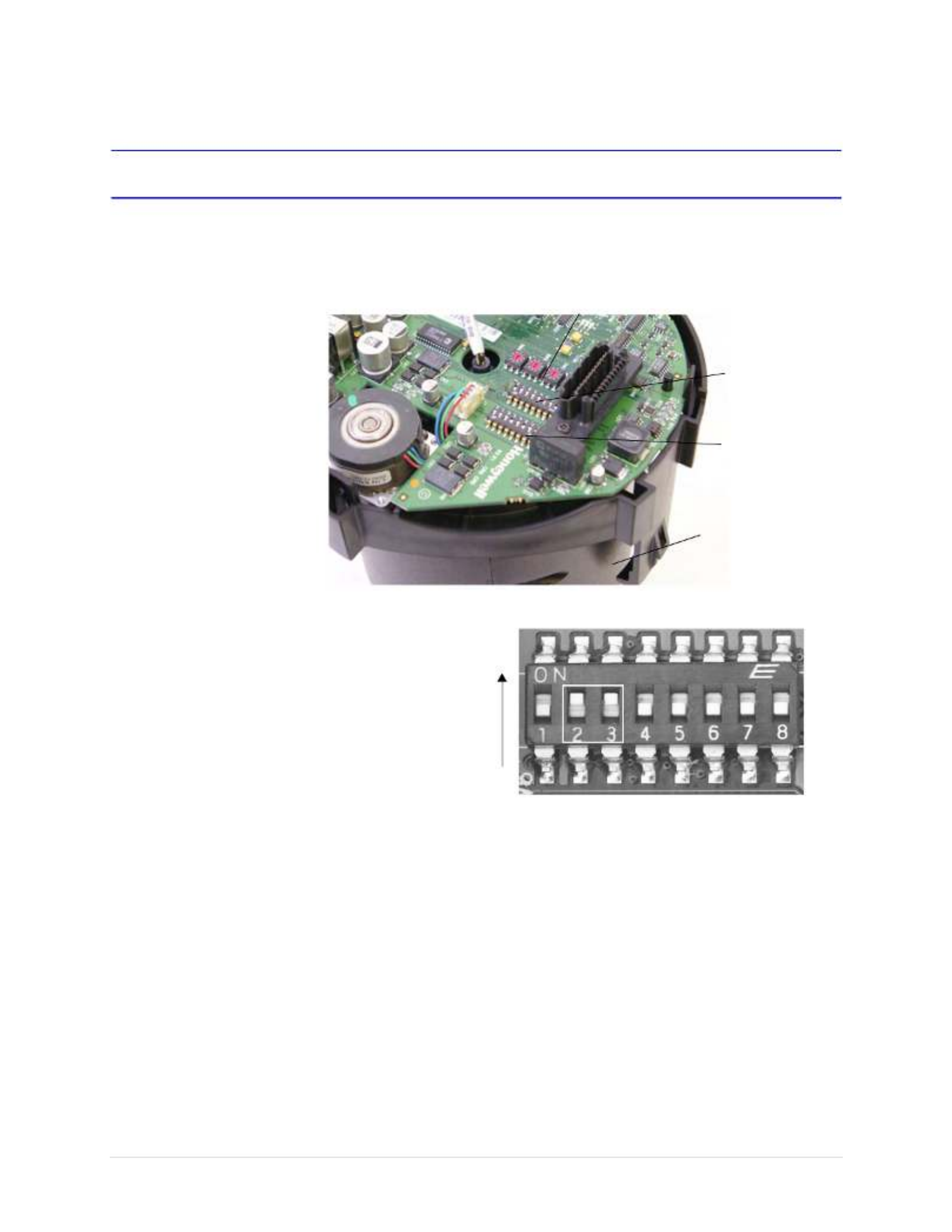
Step 2: Set the Switches on the Scan Assembly Circuit Board
Figure 3-6 (1) Circuit Board and Switch Locations (2) DIP Switch Example
SW5
SW6
Printed circuit board location
(PCB) on top of the scan assembly
Scan assembly
(includes camera)
ON
OFF
Positions 2, 3 set ON
Positions 1, 4, 5, and 6 set OFF
Example of a SW6 DIP switch setting
38400 baud rate and no parity
1
2
SW1, 2, 3, and 4 dome address
settings (for ACUIX analog only)

ACUIXTM PTZ Installation and Configuration Guide
Document 800-03140 Rev A 39
12/08
Setting the Baud Rate, Parity and Protocol (SW5 and SW6)
Note If there are invalid protocol or baud settings on SW5 or SW6 the system
defaults to MAXPRO-mode at 9600 baud rate.
1. Set the protocol on switch SW5 in the required positions using Table 3-4.
MAXPRO-mode is the default.
2. Set the baud rate and parity on switch SW6 in the required positions using
Table 3-5. 9600 baud and even parity are the defaults.
Leave SW5-8 ON. Setting the DIP switch SW5-8 to OFF enables a user to change the
address, protocol, baud rate and parity from the OSD menu (which is not recommended
with most installations).
Table 3-4 DIP Switch SW5 Protocol Settings
Protocol Name Switch Position
1 2 3 4 5 6 7 8
IntelliBus™ OFF OFF OFF OFF OFF OFF OFF ON
MAXPRO-mode OFF ON OFF OFF OFF OFF OFF ON
VCL - RS485 ON ON OFF OFF OFF OFF OFF ON
VCL Video Telemetry
(Control over Coax)
OFF OFF ON OFF OFF OFF OFF ON
Diamond ON OFF OFF OFF OFF OFF OFF ON
Pelco P ON ONOFF OFF OFF OFF OFF ON
Pelco D OFF ON ON OFF OFF OFF OFF ON

40
Installing the ACUIX Dome
Setting the Dome Address (SW1 to SW4)
1. Turn the arrows on rotary switches SW1, SW2, SW3 and SW4 to the number
required using Table 3-6 and Figure 3-7 for reference. For example:
• To set the dome address to CAM 0001, set SW1 = 1, SW2 = 0, SW3 = 0,
SW4 = 0.
• To set the dome address to CAM 0125, set SW1 = 5, SW2 = 2, SW3 = 1,
SW4 = 0.
Table 3-5 DIP Switch SW6 Baud Rate and Parity Settings
Baud Rate
and Parity
Values
Baud Rate Switch Position Parity Switch
Position
Other*
1 2 3 4 5 6 7 8
600 OFF OFF OFF OFF
1200 ON OFF OFF OFF
2400 OFF ON OFF OFF
4800 ON ON OFF OFF
9600 OFF OFF ON OFF
19200 ON OFF ON OFF
38400 OFF ON ON OFF
57600 ON ON ON OFF
115200 OFF OFF OFF ON
None OFF OFF OFF OFF
Even ON OFF OFF OFF
Odd OFF ON OFF OFF
* The defaults for SW6-7 and SW6-8 are OFF.
Each dome requires a unique address between 0000 and 9999. The addressing scheme
may be restricted due to the limitations of the controller. For example, the
HEGS5000/HEGS5001 controllers control dome addresses 1 to 256 whereas the HJZTP
control dome addresses 1 to 128.

ACUIXTM PTZ Installation and Configuration Guide
Document 800-03140 Rev A 41
12/08
Note If the dome is set to address 0000, it responds to control commands for any
address. For example, if an operator sends control commands to address
0002, the dome that has the address 0000 performs the same commands.
Figure 3-7 Circuit Board Address Switches SW1 to SW4
Step 3: Install the Mount, Adapter or Bracket
Note All the mounting hardware and field wiring is supplied by the installer.
In-Ceiling Housing
This step is part of Step 4: Install the Housing, page 47.
Table 3-6 Address Switch Assignments
Address Value
SW1 Units digit
SW2 Tens digit
SW3 Hundreds digit
SW4 Thousands digit

42
Installing the ACUIX Dome
Installing Indoor or Outdoor Pendant Mounts and Adapters
The indoor and outdoor pendant housing has optional mounts and adapters available.
• Wall mount (HDXWM1)
• Pole mount adapter (HDXPMA1)
• Corner adapter (HDXCMA1)
• Parapet or roof mount (HDPRM2)
• Ceiling mount: (HDCM1)
Installing a Wall Mount and Optional Pole or Corner Adapters
The wall mount is designed specifically for the ACUIX dome and can be mounted directly
to a vertical load-bearing surface. It supports up to 25 pounds (11.7 kg). The optional
corner and pole adapters can be used with the wall mount or with the rugged bracket.
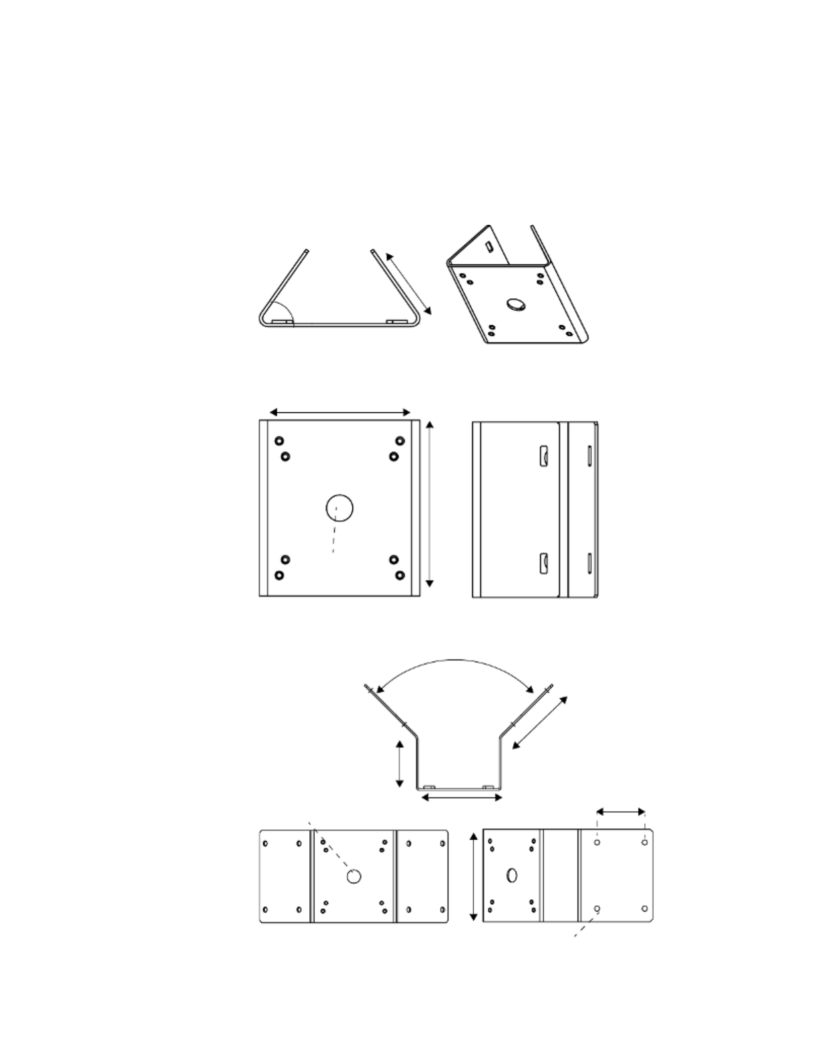
Figure 3-8 Wall Mount Dimensions
1. Route field wiring as required through the wall, pendant housing wiring access hole,
and then through the wall mount.
Approximately one foot (0.3 m) of cable must extend past the mount for all
installations.
• If installing with a corner or pole adapter also route the field wiring through the
corner or pole adapter hole.
2. (Optional) If you are installing the wall mount with a corner adapter (HDXCMA1) or
pole mount adapter (HDXPMA1) then:
Pole Adapter
• Secure the pole mounting bracket to the pole using hardware specifically
designed for the surface/material. There are four cutouts (two on each side),
0.24” x 0.75” (6 mm x 19 mm), to accommodate straps to secure the pole
mounting bracket to a pole. See Figure 3-9.
Corner Adapter
• Secure the corner bracket using hardware specifically designed for the
surface/material. The bracket has eight 0.39” (10.0 mm) holes; four on each
side. See Figure 3-10.
3. (Optional): If you are installing with a corner or pole adapter, line up the hole pattern
on the wall mount with the hole pattern on the corner or pole adapters.
4.13” (105.0 mm)
0.28” dia. (7.00 mm)
3.94” (100.0 mm)
5.71” (145 mm)
9.84”(250 mm)
ACUIXTM PTZ Installation and Configuration Guide
Document 800-03140 Rev A 43
12/08
4. Secure the wall mount to the wall using hardware specifically designed for the
surface. There are four 0.28” (7.00 mm) diameter mounting holes for securing the
mount.
Figure 3-9 Pole Mount Adapter Dimensions
Figure 3-10 Corner Adapter Dimensions
6.1" (155 mm)
6.69" (170 mm)
1" (25.4 mm)
diameter
4 cutouts (2 on each side)
3.3" (84 mm)
55 degrees
90 degrees
5.43" (138 mm)
6.3" (160 mm)
3.94" (100 mm)
6.89" (175 mm)
0.39" (10 mm) diameter (x8 through)
3.54" (90 mm)
1" (25.4 mm) diameter

44
Installing the ACUIX Dome
Installing a Parapet or Roof Mount
Note The parapet and roof mount is designed for installing a dome on the inside of
a roof parapet or onto a flat roof surface. The mount has a maximum load
rating of 20 pounds (9 kg).
1. Route the field wiring through the dome wiring access hole and through the center
of the parapet mount.
Approximately one foot (0.3 m) of cable must extend past the mount.
2. Secure the mount to the parapet or roof using as many of the mounting holes as
possible. The minimum recommended is five fasteners on each side of the
mounting plate. See Figure 3-11.
Figure 3-11 Parapet and Roof Mount Parts and Dimensions
1 Nut and socket
2 Mounting arm (2 pc)
3 Coupling (x1)
4 Base plate (x1)
5 Support angle (x2)
6 Bracket angle (x1)
7Hexagon head bolt, nuts and spring
washers M10 (x12
Not shown
Panhead screw M4 x 8 (x2)
Set screw M5 x 6 (x3)
Wrench head bolt M6 x 30 (x3)
Pipe fastener (x1)
Hexagon nut M6 (x3)
HEX Allen wrench, 2.5 mm (x1)
HEX Allen wrench, 5 mm (x1)
Flat washer M10 (x12)
Teflon seal tape (x1)
2
3
1
4
5
6
7
24.72” (628 mm)
39.60” (1006 mm)
Parapet
Roof
12.20” (310 mm)
35.83”
(910 mm)
5.9”
(150 mm)
17.71” (450 mm)

ACUIXTM PTZ Installation and Configuration Guide
Document 800-03140 Rev A 45
12/08
Installing a Ceiling Mount
For both indoor and outdoor pendant housings, the ceiling mount is installed directly to
a horizontal load-bearing surface and supports up to 25 pounds (11.7 kg).
1. Route field wiring as required into the dome wiring access hole and through the
center of the ceiling mount.
Approximately one foot (0.3 m) of cable must extend past the mount.
2. Secure the ceiling mount to the ceiling using hardware specifically designed for the
surface.
There are four 0.47” (12.00 mm) diameter mounting holes for securing the mount.
See Figure 3-12.
Figure 3-12 Ceiling Mount Dimensions
Installing the Rugged Dome Bracket and Adapters
Note If you are using the optional pole or corner adapters, also see Figures 3-9 and
3-10 respectively.
1. Use the hole pattern on the bracket to drill holes in the wall, ceiling or roof. Use the
appropriate hardware for the mounting surface.
2. (Optional) If you are installing the rugged bracket with a corner adapter (HDXCMA1)
or pole mount adapter (HDXPMA1) then:
Pole Adapter
• Secure the pole mounting bracket to the pole using hardware specifically
designed for the surface/material. There are four cutouts (two on each side),
0.24” x 0.75” (6 mm x 19 mm), to accommodate straps to secure the pole
mounting bracket to a pole.
14.76” (375.0 mm)
5.51” (140.0 mm)
PF 1.5”
3.58" (91.0 mm) 4.56” (116.0 mm)
0.47” (12.0 mm) diameter

ACUIXTM PTZ Installation and Configuration Guide
Document 800-03140 Rev A 47
12/08
Figure 3-14 Rugged Bracket Dimensions
Step 4: Install the Housing
ACUIX Power Requirements
• Each ACUIX requires a 24 VAC ± 10% power source measured at the housing.
• For outdoor installations, ensure a 24 VAC at 2.5A power source is available.
• For indoor installations, ensure a 24 VAC at 1.9 A power source is available.
0.21" (5.3 mm)
diameter (x4)
0.31" (8 mm)
diameter (x4)
3.9" (100 mm)
3.5" (89 mm)
6.5 " (165 mm)
2.6" (67 mm)
4.1" (105 mm)
1.7" (44 mm)
2.6" (67 mm)
3.5" (89 mm)
The outer holes can be used with the
corner and pole adapter

48
Installing the ACUIX Dome
Installing the In-Ceiling Housing (Hard or Dropped Ceiling)
Note The in-ceiling housing field wiring access hole is 1.039 in (26.4 mm) in
diameter and accepts ¾ in electrical fittings.
The following explains how to install into a dropped (false) ceiling or a hard ceiling. For
dropped ceiling installations, use a separately ordered ceiling plate (Honeywell part
number 517082-7130). In addition to the other items normally supplied by the installer,
the following may be required:
• Tape or plastic channel to prevent dust and material from dropping from the ceiling.
• Safety cable - a 3/32” (approximately 2.4 mm) plastic coated aircraft cable is
recommended and a looping sleeve.
Figure 3-15 In-ceiling Housing with Wing Tab Spacing
Field wiring access hole [1. 04"
(26.44 mm) diameter]
Wing tabs (x 3)
Attach safety cable to bracket
Turning screws on wing tabs
The correct way to space wing tabs

50
Installing the ACUIX Dome
Installing the Indoor and Outdoor Pendant Housing
Figure 3-17 Indoor Pendant Housing
1. If not already done, route the field wiring:
• Through the housing mount, then
• Through the field wiring access hole in the housing, and then
• Through the access hole in the interface board installed in the housing.
Note The wiring must extend at least one foot (0.3 m) past the mount for wiring
purposes.
2. Install the housing on the mount. Make sure there is Teflon ® tape on the threaded
nipple part of the housing.
Installing the Rugged Housing
Figure 3-18 Rugged Housing and Bracket
1. Complete the bracket installation as described previously.
2. If not already done, route the field wiring:
a. Through the field wiring access hole in the housing, and
b. Through the access hole in the interface board installed in the housing.
3. Install a 0.75"(19 mm) conduit fitting in the hole on the housing.
Threaded nipple
Field wiring
access hole

52
Installing the ACUIX Dome
Figure 3-20 Terminal Blocks J6 (Data) and J7 (Video)
Figure 3-21 Terminal Block J4 (Contacts)
J6
RS485 Data
Wiring
J7
UTP Wiring
Contact 1
Contact 2 Contact 3
Contact 4
Table 3-7 Terminal Strip Pins and Functions (J1, J4, J6 and J7)
Terminal Strip J1 Function
Pin 1 24 VAC input A
Pin 2 ESD (electrostatic discharge) grounding
Pin 3 24 VAC input B
Terminal Strip J4 Function
Pin 1 Contact 1 (A1)
Pin 2 Contact common (CM)
Pin 3 Contact 2 (A2)
Pin 4 Contact 3 (A3)
Pin 5 Contact common (CM)
Pin 6 Contact 4 (A4)
Terminal Strip J6 Function
Pin 1 RS485 data (+) communication signal
Pin 2 RS485 data (-) communication signal
Pin 3 Shield (SH)
Terminal Strip J7 Function
Pin 1 Video + (V+) (UTP wiring)
Pin 2 Video – (V–) (UTP wiring)

ACUIXTM PTZ Installation and Configuration Guide
Document 800-03140 Rev A 53
12/08
Connecting the Wiring
Note Use the above tables and figures as references during installation.
1. Route the field wiring ((data, power, video, contact):
a. Through the field wiring access hole in the housing, and
b. Through the access hole in the interface board installed in the housing.
Note At the appropriate time during the installation, ensure the field wiring access
hole is sealed to prevent anything from getting inside the housing.
2. Remove the plug-in terminal blocks on terminal strips J1 (24 VAC) and J6.
3. (Optional): If required, set up the contact (alarm) input terminal block:
Note The terms contact and alarm are used interchangeably to mean the same
thing. Alarm is currently displayed on the OSD, although contact is a better
description since it is not an audible alarm but a change in electrical state to
the contacts resulting in a programmed response.
a. Remove the plug-in terminal block on terminal strip J4.
b. Connect a twisted-pair cable from each peripheral contact to each input at the
number terminal and the common terminal on terminal strip J4. The contact is a
dry contact between the terminal and the common terminal. The contacts can
be configured as normally open (NO) or normally closed (NC).
Note The common terminals are doubled up.
All contact input connections MUST be passive contacts.

54
Installing the ACUIX Dome
Note The contact cabling should not be terminated until standard operation of the
dome is tested.
c. Configure the contacts as required.
4. Loosen the screws on the terminal strip and insert the 24 VAC power wires, data
wires, video wires (if UTP is selected) and contact wires in the correct positions on
terminal strips J1, J4, J6, and J7. See Terminal Block and PIN Connections, page
51.
• Ensure the yellow labeled terminal strip is plugged into the yellow labeled
connector and the white labeled terminal strip is plugged into the white labeled
connector.
Note Both terminal strips J1 and J6 accept 26–12 AWG wire. If larger or smaller
field-run wire is required, a 26–12 AWG wire must be spliced onto the field
wire for insertion into the terminal strip.
Note Ensure the correct connections are made with terminal strip J6 - RS485 data
(-) and data (+) otherwise polarity can be an issue.
Note You can connect the data cable shield to Pin 3 (SH) on terminal strip J1. Use
this connection for looping the shield through to the next dome in the
daisychain. It is not connected to the housing interface board.
5. Tighten the screw on the terminal strip to secure the wires.
6. Connect incoming coaxial cable to coaxial pigtail on the housing interface board.
Tighten the screw on the terminal strip to secure the wiring.
7. Plug the terminal strips into the respective connectors on the interface board. If you
are using a coaxial cable for video, connect the field run coaxial cable to J3.
Note When connecting field wiring, connect to either J3 or J7, not to both at the
same time.
8. If applicable, secure the wires from the terminal strip and BNC connector together
with a wire tire to ensure the cabling does not prevent the secure closure of the
housing and lower dome.
9. Feed extra wire and cable up through the hole in the housing and route it so that it
doesn't interfere with the scan assembly when it is inserted.

ACUIXTM PTZ Installation and Configuration Guide
Document 800-03140 Rev A 55
12/08
Step 6: Install the Scan Assembly into the Housing
Note Scan assembly installation is the same with all housing types.
1. Carefully remove the plastic lens cap from the scan assembly. Do not touch the
lens.
2. Rotate and line up the scan assembly yellow label to the mounted housing yellow
label.
3. Gently push the scan assembly into the housing until the two guides on the scan
assembly lock/snap into the holes on the housing guides.
4. Gently pull down on the assembly to ensure it has properly latched into place.
Figure 3-22 Installing the Scan Assembly into the Housing
Scan assembly locking guides Up
Rotate to align with the
housing yellow labels
56
Installing the ACUIX Dome
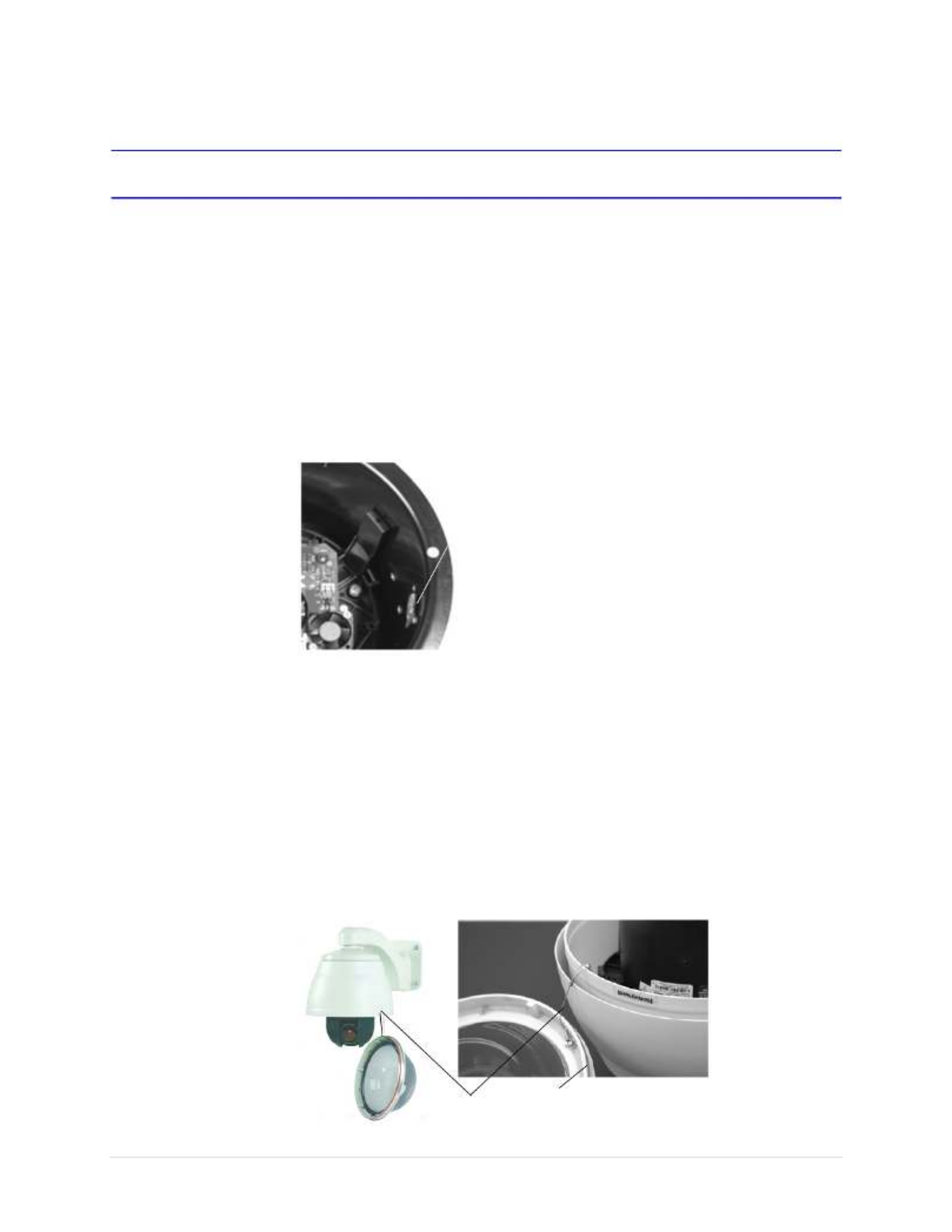
Step 7: Install the Lower Dome onto the Housing
Installing the In-Ceiling Lower Dome
1.Clip the lanyard to the mounting post inside the housing.
2. Align the lower dome tab hooks with the three mounting posts on the housing.
3. Twist to lock the lower dome into the housing.
4. If applicable, continue the next steps to configure the dome.
Figure 3-23 In-ceiling Housing Lanyard Bracket
Installing the Indoor or Outdoor Pendant Lower Dome
1. Clip the lower dome lanyard to the housing bracket.
2. Confirm that the o-ring is in place around the lower dome and press the lower dome
into the housing
3. Tighten the screws to secure the lower dome to the housing.
4. If applicable, continue the next steps to configure the dome.
Figure 3-24 Lower Dome with Lanyard Attached to Pendant Housing
Clip the lanyard from the lower
dome to the bracket inside the
housing
Lanyard O-ring on lower dome

58
Installing the ACUIX Dome

ACUIXTM PTZ Installation and Configuration Guide
Document 800-03140 Rev A 59
12/08
Before You Begin Configuring
Complete the following before configuring your ACUIX dome:
•Important Information about Controllers and Protocols, page 59
•Step 1: Prepare the Controller and Monitor for Use, page 60
•Step 2: Turn on the Dome and Find the Mechanical Home, page 60
•Step 3: (Optional) Learn about the HJZTP Joystick Controller, page 61
•Step 4: Learn How to Use the Special Presets, page 63
•Step 5: Open the OSD Menu and Start Configuring, page 65
Important Information about Controllers and Protocols
The ACUIX is compatible with the following controllers and protocols:
• HJZTP controller using the VCL, MAXPRO-mode or Diamond protocols
• HMAX082/HMAX162 Matrix Switcher and HKJMMTP controller using VCL UTP / coax
control protocol
• Pelco P and Pelco D third party protocols and controllers
• HEGS5000/5001 controller with Diamond protocol
• IntelliBus protocol
In general, protocols allow cross compatibility between products and manufacturers.
Because the ACUIX dome is designed to work with a variety of controllers, DVRs and other
hardware, deciding what protocol to use when setting up a system is challenging. It is also
not possible to describe all the tasks using all combinations of protocols and hardware.
Therefore, this guide is a supplement to the hardware users guides and are based on the
use of the Honeywell HJZTP joystick controller.

60
Before You Begin Configuring
Note The current HJZTP Controller User Guide indicates it can be set to either VCL
or Diamond protocols. The ACUIX default protocol is MAXPRO-mode. For the
HJZTP controller ONLY, MAXPRO-mode can be considered exactly the
same as Diamond protocol. From the user’s perspective, the
MAXPRO-mode allows access to the same special presets as with the VCL
protocol.
If other controllers, DVRs or protocols are used, MAXPRO-mode, Pelco P or Pelco D
protocols also operate in a similar way as described for the VCL protocol. That is to
say, how you access the special presets and on-screen display (OSD) is approximately the
same.
Step 1: Prepare the Controller and Monitor for Use
Before making configuration changes with any controller, you need to:
1. Ensure the dome is assigned to the controller being used. Refer to the applicable
controller user guide for instructions.
2. Confirm video is displaying on the monitor.
3. Confirm there is manual control of the dome using the controller. To manually control
an ACUIX and pan, tilt, zoom, focus, and iris, the address must be selected as the
control dome. If the dome ID is turned on in the Display Options menu, the letter M is
displayed on the monitor.
Step 2: Turn on the Dome and Find the Mechanical Home
The dome locates other referenced positions (such as presets) using a mechanical home
(or index) position as a reference point. The dome also needs to locate the mechanical
home/index position before responding to the first pan, tilt, and zoom command. For all
protocols the operator can send any command to the dome, but what happens when the
dome is first turned on depends on options as listed in Table 4-1.

ACUIXTM PTZ Installation and Configuration Guide
Document 800-03140 Rev A 61
12/08
How to Find Home (MAXPRO-mode or Diamond Protocols)
• On the controller, press and hold the Fn key, then press F1.
Note For protocols VCL, VCL UTC, Pelco P and Pelco D there is no command to
find home during regular operation.
Step 3: (Optional) Learn about the HJZTP Joystick Controller
The joystick on any controller is used to control the pan and tilt functions. The speed of pan
and tilt is relative to the amount of movement applied to the joystick. The following is a brief
overview of the operation of the HJZTP controller (Diamond, MAXPRO-mode or VCL
protocols available).
For the HJZTP controller:
• the maximum pan speed can be between 120°, 240°, or 480° per second.
• the maximum tilt speed is one-half the maximum pan speed.
• if the maximum pan speed is set to 240° per second, the maximum tilt speed is set to
120° per second.
Table 4-1 Display Options at Dome Power Up
When the dome first
powers up
If Then
Start up screen text The startup screen msg is
ON
the protocol, baud rate, parity, data bits, camera
model, and firmware release dates and versions
display on the monitor.
The startup screen msg is
OFF
an X displays on the monitor.
Finding home The dome is set to find home
on startup
the message Finding Home... displays on the
monitor followed by Home Found...
If the dome is not set to find
home on startup
it finds home when the first control command is
received at which time the operator can control the
dome with the controller.

62
Before You Begin Configuring
Figure 4-1 HJZTP Controller Layout
Function buttons Number buttons: Joystick controller
Iris and focus buttons
Preset buttons
Wash, wipe, aux
and lock
camera, preset, sequence,
monitor FN
auto 180, autopan
Mode
123456
78
910
Table 4-2 HJZTP Controller Functions
No. Button Use
1 F1, F2, F3,
F4
F5 (enter)
F6 (menu)
• Move up (F1), down (F2), left (F3)and right (F4)
• Press F5 to enter a menu or item.
• Press F6 to enter or exit the current menu; In MAXPRO-mode/Diamond mode, it
sends the ESC command to the dome.
2 0 – 9 Press the number corresponding to the submenu or list selection.
3 iris + / -
auto iris
• Press + (Open) or - (Close) to manually change the camera’s iris. The camera
auto-exposure must be off.
• Press auto above the iris control buttons to put the camera in auto-iris mode.
focus + / -
auto focus
• Press + (Far) or - (Near) on the controller to manually focus the camera when you
zoom in and out.
• Use the OSD menus to set auto focus. The auto focus can be set to come on when
the camera is zoomed or when the dome undertakes a pan, tilt or zoom action. When
the zoom is changed it must automatically focus; optionally when pan, tilt or zoom is
changed it must also auto focus.
4 presets 1–4 Press 1 to 4 preset number to go to a programmed location.
5 move
up/down,
left/right
Tilt the joystick up or down.
Move the joystick left and right to pan.
Note If the pan and/or tilt functions of the ACUIX are reversed through the on-screen
setup menus (Pan Reverse or Tilt Reverse is enabled), joystick up performs tilt
down, joystick down performs tilt up, joystick left performs pan right and joystick
right performs pan left.
zoom in/out Rotate the top of the joystick clockwise to zoom in and counter-clockwise to zoom out.

ACUIXTM PTZ Installation and Configuration Guide
Document 800-03140 Rev A 63
12/08
Step 4: Learn How to Use the Special Presets
There are several special presets reserved for controlling and programming the dome.
Depending on the protocol, approximately 150 presets are available for custom
programming. Presets 72–99 are reserved for the available special presets listed in
Table 4-3 and described in this guide.
Note The text displayed on the OSD with MAXPRO-mode is a shortened version of
the descriptions in Table 4-3.
Various presets are available for programming with all protocols with exceptions as noted.
6 mode Press to toggle between modes. To toggle between PTZ mode ON and DVR and MUX
OFF, press and hold Fn, then press the mode button to select PTZ.
Note The PTZ domes can be controlled while the controller is in any mode (for example,
MUX, DVR, or PTZ).
7 wash
wipe
aux
lock
• Press and hold wash to toggle ON and OFF and insert a line.
• Press wipe to toggle ON and OFF and delete a line.
• Press aux as part of the sequence to open the OSD or while in list menus, to display
the next page of items.
• Press lock to exit OSD and LCD menus and return the dome and controller to normal
operation.
8 camera
preset
sequence
monitor
• Press a dome number X camera to select that dome to display on the monitor.
• Press preset X [preset number] to access presets and tours.
• Press sequence to send 'S' to the dome and save settings.
• Pressing a number (1 to 4) followed by monitor selects that auxiliary monitor for
control by the controller (the spot monitor number is displayed on the LCD). If you
press monitor without first entering a number, the controller goes back to the main
monitor (MAIN displays on the LCD).
9 auto 180°
autopan
• Press auto 180° to view a person walking underneath the dome; pan the dome 180°
at the maximum speed.
• Autopan is used with presets and tours.
10 Fn • To return to manual control, press and hold , then press Fn F6 (menu). The 'return to
manual' command is used to cancel automatic dome actions.
• To return to mechanical home, press and hold , to send the dome Fn, then press F1
to its mechanical home position.
Table 4-2 HJZTP Controller Functions
No. Button Use

66
Before You Begin Configuring
Opening a Submenu or Selecting a Menu
• Press a number beside the menu option. The numbers either toggle between the
available choices or opens another menu.
• Move the joystick up or down the menu and press F5 (enter).
Exiting or Escaping from a Menu
Note Depending on the protocol used, for example with the HJZTP controller, the
monitor displays different exit instructions.
To exit or escape from a menu (VCL):
• The monitor displays press Iris Close. Press Iris (-).
In VCL protocol, press Iris (+) to open a menu and Iris (-) to close a
menu. The OSD uses the terms Iris Open and Iris Close to mean the
same thing respectively. In some menus, you can also use these
keys to toggle between values.
To exit or escape from a menu (MAXPRO-mode or Diamond):
• The monitor displays press Esc. When using an HJZTP controller, press lock.
Iris open
Iris close

Document 800-03140 Rev A 67
12/08
5
Configuring the ACUIX Dome
In this section:
•Opening and Displaying the OSD Camera Menu, page 67
•Configuring Display Settings, page 69
•Configuring the Pan, Tilt and Zoom (PTZ) Dome Settings, page 72
•Configuring the Image Quality and Video Display Settings, page 74
•HDXG Cameras: Configuring Camera Settings, page 80
•Configuring Contacts/Alarms, page 83
•Configuring the Controller Settings - Pan and Tilt Reverse, page 85
•Configuring the Lift and Gain Settings and PWM, page 86
•Configuring Mimic Tours, page 87
•Configuring Default Functions: Presets and Tours, page 89
•Configuring Presets and Preset Tours, page 90
•Configuring Privacy Zones, page 93
•Configuring Sectors, page 96
Opening and Displaying the OSD Camera Menu
• Open the OSD by pressing 90 X Preset.
After each step it is assumed that you exit and save after each task using the
applicable method based on the protocol and controller.
68
Configuring the ACUIX Dome
Figure 5-1 On Screen Display (OSD) Menu Tree
1. Language English (default); Spanish (Espanol); Polish (Polski); German (Deutsch); Italian (Italiano); French (Francais); Dutch (Nederlands); Czech
2. Display Options 3. Control Options 4. Dia
g
nostic O
p
tion
s
1
5. Camera O
p
tions
1
6. Function Programming 7. Enhanced Features
1. Camera Msg 1. PASS 1. Coordinates 1. Zoom and Focus 1. PTZ Mimic Tour Menu 1. Video Gain/PWM Settings
(1) Max Digital Zoom Mag (1) Run a Mimic Tour (1) Video Gain (UTP)
(2) Manual Zoom Speed (2) Program a Mimic Tour (2) Lift PWM Level 0-100
Available all cameras
(3) Delete a Mimic Tour (3) Gain PWM Level 0-100
(4) Char White Level 0-100
2. Sectors 2. Auto-Pivot 2. N/A 2. Exposure Control 2. Program a Preset Tour 2. N/A
(1 or 2) Auto Exposure Level
(2 or 8) Backlight Comp
3. Preset Names 3. Program Alarms 3. Clear the Memory 3. NightShot Control 3. Privacy Zone Options
3
3. N/A
(1) Program Alarms (1) NightShot Mode (1) Change PrivZone Priority
(2) Set Alarm Condition (2) NightShot (2) Enable/Disable PrivacyZone
(3) Activate (3) Privacy Zone Color
(4) Deactivate
4. Digital Zoom Mag 4. Set Pan and Tilt Options 4. N/A 4. White Balance 4. List PS/PT/Sectors 4. N/A
(1) Manual Speed (deg/s) (1) High Light WB Mode (1) Presets
(2) Pan Reverse (2) Low Light WB Mode (2) Preset Tours
(3) Tilt Reverse (3) Enter High Lght 28dB (3) Sectors
(4) - 5 deg Tilt Limit (4) Enter Low Lght 28dB
(5) Find Home on Startup (5) Manual White Balance
(6) Pan Offset
Offset
Set Pan Offset
(7) Startup State Restore
5. Start up Screen Msg 5. Set Default Function 5. N/As 5. Still Preset 5. Program Sector
3
5. Time and Date Settings
(1) Display Time
(2) Display Date
(3) Time Format
(4) Change Time
(5) Change Date
6. Change Camera Name Loc 6. Auto Focus 6. Restore Default Settings 6. Vert Phase Edge 6. Program Privacy Zone
3
6. Display Supply Voltages
7. Change Sector Name Loc 7. Preset Tour Auto Focus 7. Scan and Camera Reset 7. Vert Phase 7. Delete PS/PT/PZ/Sectors
8. Crosshairs 8. Electronic Image Stabilization
2
9. Dome Name Settings 9. WDR/Motion Detection
(1) Set Dome Name (1) Wide Dynamic Range
(2) Display Dome Name (2) Motion Detection
(3) Change Dome Name
Location
1 Feature and menu availability is camera dependent
2 HDXG only
3 MAXPRO-mode, VCL, UTC and Pelco P and D protocols only
ACUIX On-Screen Display (OSD) Menus

ACUIX PTZ Installation and Configuration Guide
Document 800-03140 Rev A 69
12/08
Configuring Display Settings
Note This section also includes Enhanced Features menu options.
Note Remember you access the OSD by pressing 90 X Preset.
Task/Action with Default Notes
Changing the On-screen Language
• Scroll to select 1 Language X English (default), French
(Francais), German (Deutsch), Italian (Italiano), Spanish
(Espanol), Dutch (Nederlands), Polish (Polski).
Displaying the Dome (Camera Msg) Number
• Select 2 Display Options X1 Camera Msg X ON (default) or
OFF.
See Note 1 page 71.
Changing the Digital Zoom Magnification Level (Digital Zoom Mag)
• Select 2 Display Options X X4 Digital Zoom Mag ON or OFF
(default).
Displays the magnification level on the
right side beside the dome ID. If the
location changes based on dome name,
this text also moves.

70
Configuring the ACUIX Dome
Changing the Start up Screen Msg
• Select 2 Display Options X5 Start up Screen Msg X ON
(default) or OFF.
Changing Dome (Camera) Name/Msg Loc (Location)
• Select 2 Display Options X6 Change Camera Name Loc X
Depending on the protocol, use either arrows or the joystick to
move the text up or down the monitor to position as required.
See Note 1 page 71.
Displaying Crosshairs
• Select 2 Display Options X8 Crosshairs XON or OFF
(default).
Useful with pan offset.
Setting a Dome Name
• Select 2 Display Options X9 Dome Name Settings X1 Set
Dome Name X enter a 24-alphanumeric name for the dome.
Depending on the protocol, use either arrows or the joystick to
scroll the number and letter choices.
See Note 2 page 71.
Displaying a Dome Name
• Select 2 Display Options X9 Dome Name Settings X2
Display Dome Name XON or OFF (default).
See Note 2 page 71.
Changing Dome Name Location
• Select 2 Display Options X9 Dome Name Settings X3
Change Dome Name Location X Depending on the protocol,
use either arrows or the joystick to move the text up or down
the monitor to position as required. The default is top left.
See Note 2 page 71.
Displaying the Time
1. Select 7 Enhanced Features X 5 Time and Date Settings X
1 Display Time X
2. Select ON to display the time at the lower left center of the
monitor in HH:MM:SS (24 hour format) or AM/PM (12-hour
format) or OFF (default).
Displaying the Date
1. Select 7 Enhanced Features X 5 Time and Date Settings X
2 Display Date X
2. Select ON to display the time at the lower right center of the
monitor in DD-MMM-YYYY format or OFF (default).
Task/Action with Default Notes

ACUIX PTZ Installation and Configuration Guide
Document 800-03140 Rev A 71
12/08
Setting the Time Format to Display
1. Select 7 Enhanced Features X 5 Time and Date Settings X
3 Time Format X
2. Select 24 hours (default) to display the time as HH:MM:SS or
12 Hours to display the time with AM or PM.
Setting the Time
1. Select 7 Enhanced Features X 5 Time and Date Settings X
4 Change Time X
2. Enter the new time in HH:MM:SS (hours:minutes:seconds)
format.
The time must be entered in 24-hour format.
3. Press Enter to change to the new time or press ESC to leave
the time as originally displayed.
Setting the Date
1. Select 7 Enhanced Features X 5 Time and Date Settings X
4 Change Date X
2. Enter the new date in YYYY-MM-DD (year-month-day) format.
3. Press Enter to change to the new date or press ESC to leave
the date as originally displayed.
Display Options Notes
(1) Applies to the numerical number assigned to each dome (displays on the monitor as CAM) during installation
using the address switches on the scan assembly. To name and position the text on the display see Changing
Dome Name Location on page 70.
(2) Applies to the user assigned alpha-numeric name you can assign to each dome. The dome may also have a
number assigned during installation when the address switch settings are assigned.
Task/Action with Default Notes

72
Configuring the ACUIX Dome
Configuring the Pan, Tilt and Zoom (PTZ) Dome Settings
Note Remember you access the OSD by pressing 90 X Preset.
Task/Action with Default Notes
Turning the Pan and Tilt Speed Range (PASS) ON and OFF
• Select 3 Control Options X1 PASS X ON (default) or OFF. PASS is a function of the lens zoom
angle. The maximum pan and tilt speeds
are reduced when the lens zooms in. For
example, the pan and tilt functions are
slow when the camera is set at 12X zoom.
The higher the zoom magnification, the
slower the speed.
Turning the Auto Pivot ON or OFF
1. Select 3 Control Options X2 Auto Pivot XON or OFF
(default).
Track people passing directly underneath
the dome. The dome automatically turns
180° when it reaches its lower limit. It
continues to tilt up as long as the control
tilt function remains in the down position.
When the dome reaches its tilt up limit, it
returns to normal operation.
Changing the Manual Pan and Tilt Speed
• Select 3 Control Options X4 Set Pan and Tilt Options X1
Manual Speed X 120°/sec, 240°/sec, or 480°/sec (default).
The maximum tilt speed is half of the
maximum pan speed.

ACUIX PTZ Installation and Configuration Guide
Document 800-03140 Rev A 73
12/08
Turning the -5° Tilt Limit ON or OFF
1. Select 3 Control Options X4 Set Pan and Tilt Options X4
–5° Tilt Limit X
2. Select ON to position the unit tilt to 5° above horizontal or OFF
(default).
Allows the camera to tilt 5 degrees above
horizontal.
Finding the Mechanical Home on Startup
1. Select 3 Control Options X4 Set Pan and Tilt Options X5
Find Home on Startup X
2. Select:
•OFF (default) to set the unit to find home when powered up
and the dome performs a control command.
• ON to set the dome to find the mechanical home (or index)
position after an initial startup delay of 15 seconds.
3. If you selected ON, the message Extreme Caution: This
will cause the scan to move immediately on
startup... displays.
• Select Y (yes) to continue or N (no) to cancel.
When a privacy zone is enabled, no video
is shown during the finding home process
and privacy zones are not recognized
until the dome reaches home. Once the
dome finds home, a picture can be
viewed on the monitor unless a privacy
zone overlaps with this home setting.
Turning the Pan Offset ON or OFF
• Select 3 Control Options X4 Set Pan and Tilt Options X6
Pan Offset X1 Pan Offset XON or OFF (default).
Pelco P and D protocols only: The pan
offset feature is not available due to the
preset index starting at 1 instead of 0.
Setting the Pan Offset
1. Select 3 Control Options X 4 Set Pan and Tilt Options X6
Pan Offset X1 Pan Offset .XON
2. Press 0 X Preset.
3. Position the dome where preset 0 is expected to be. If it does
not go to the previously known position for preset 0, the offset
function cannot be used.
4. Select 3 Control Options X X 4 Set Pan and Tilt Options 6
Pan Offset
X .2 Set Pan Offset
5. Test the setting. Reposition the unit, and select 0
X Preset to
confirm it returns to the position programmed.
Pelco P and D protocols only: The pan
offset feature is not available due to the
preset index starting at 1 instead of 0.
For all other protocols, preset 0 is used to
define the location of the pan setting; you
must know the original positioning of
preset 0 to complete these steps.
The pan offset feature is useful when a
new scan assembly is installed in a dome
and you want to transfer programming
from the previous scan assembly to the
new dome using the upload/download
feature.
Task/Action with Default Notes
74
Configuring the ACUIX Dome
Configuring the Image Quality and Video Display Settings
Note The Camera Options menu is highly variable and camera model dependent.
Note Remember you access the OSD by pressing 90 X Preset.
Turning the Start Up State Restore ON or OFF
1. Select 3 Control Options X4 Set Pan and Tilt Options X 6
Pan Offset X 7 Startup State Restore X
2. Select
•OFF (default).
•ON to set the dome to return to the state of operation at the
last loss of power.
3. If you selected ON, the message Extreme Caution: This
will move the dome to previous shutdown
position on startup... displays.
• Select Y (yes) to continue or N (no) to cancel.
Displaying Pan and Tilt Coordinates
1. Select 4 Diagnostic Options X1 Coordinates X
2. Select ON to display the pan (azimuth) and tilt
(elevation/declination) along the bottom of the monitor or OFF
(default).
Task/Action with Default Notes
Only qualified technical personnel should use the Camera Options menu to change
configurations as these changes can make the recorded images unusable.

ACUIX PTZ Installation and Configuration Guide
Document 800-03140 Rev A 77
12/08
Activating NightShot (TDN)
1. Set NightShot mode to Auto.
2. Select 5 Camera Options X 3 NightShot Control X 3
Activate NightShot.
3. Toggle between the available gain and shutter speed values.
a. Gain Settings
• 0dB, 2dB, 4dB, 6dB, 8dB, 10dB, 12dB, 14dB, 16dB,
18dB, 20dB, 22dB, 24dB, 26dB, 28dB.
b. Shutter Speed Settings
• PAL = 1/3 sec, 1/6 sec, 1/12 sec, 1/25 sec, or 1/50 sec.
• NTSC = 1/4 sec, 1/8 sec, 1/15 sec, 1/30 sec, or 1/60
sec.
Available with camera models HDXJ,
HDXF and HDXG (NOT HDXA).
Keep the activation and deactivation
settings slightly apart to ensure that there
is always some deadband between the
activate and deactivate levels. The
amount of deadband can be adjusted to
prevent the dome from oscillating
between the NightShot activated and
deactivated modes.
Deactivating NightShot (TDN)
1. Select 5 Camera Options X 3 NightShot Control X 4
Deactivate NightShot.
• Toggle between the available gain and shutter speed values.
a. Gain Settings
• 0dB, 2dB, 4dB, 6dB, 8dB, 10dB, 12dB, 14dB, 16dB,
18dB, 20dB, 22dB, 24dB, 26dB, 28dB.
b. Shutter Speed Settings
• PAL = 1/3 sec, 1/6 sec, 1/12 sec, 1/25 sec, or 1/50 sec.
• NTSC = 1/4 sec, 1/8 sec, 1/15 sec, 1/30 sec, or 1/60
sec.
Available with camera models HDXJ,
HDXF and HDXG (NOT HDXA).
Task/Action with Default Notes

ACUIX PTZ Installation and Configuration Guide
Document 800-03140 Rev A 79
12/08
Setting the Red and Blue Gain
1. Turn Manual White Balance ON.
2. Select 5 Camera Options X4 White Balance X
• [2 or 6] Red Gain
• [3 or 7] Blue Gain
3. Toggle to select a value based on camera model:
• For models HDXA, HDXJ and HDXF, select from a range
between 0 (low) and (high). The default is 200.255
• For model HDXG, select from a range between 0 (low) and
511 (high). The default is 128.
Available with all camera models.
For models HDXA, HDXJ and HDXF, the
menu selection is 6 Red Gain and 7 Blue
Gain.
For HDXG, the menu selection is 2 Red
Gain and 3 Blue Gain.
Enabling or Disabling Vertical Phase Edge (Line Lock)
Caution Requires an AC power supply.
• Select 5 Camera Options X X6 Vert Phase Edge Enabled or
Disabled (default).
Available with all camera models.
If you enable the Vertical Phase Edge,
you can set the Vertical Phase from 0 to
359.9.
Setting the Vertical Phase Edge (Line Lock)
Caution Requires an AC power supply.
1. Enable the Vertical Phase Edge.
2. Select 5 Camera Options X 7 Vert Phase X enter a number
between 0 (default) and 359.9.
Available with all camera models.
Turning Motion Detection ON or OFF
1. Select 5 Camera Options X9 Motion Detection.
The message This will Disable Motion Detection.
Are you sure that you want to do this? displays.
2. Select Y (yes) to disable motion detection or N (no) to cancel.
3. Select ON or OFF.
• If set to ON, interlace scanning, EIS and the default
functions are all automatically disabled.
• If set to ON and an operator sends a command to the
dome, then motion detection is automatically set to OFF
and disabled. The operator must access the setup menu to
re-enable it.
• If set to ON and manual operation is in progress, the
feature is disabled for 30 seconds and returns to normal
operation after the PTZ operation concludes.
Available with camera models HDXJ,
HDXF and HDXG (NOT HDXA).
When motion is detected, the message
Motion Detected is displayed on the
monitor and remains on the video until
the dome receives a pan, tilt, or zoom
command.
Motion detection is automatically
disabled as soon as motion is detected to
avoid multiple triggers from the same
event. The feature is turned on again after
a one minute delay of any event.
If the dome is in IntelliBus protocol, for
each Motion Detect Event an IntelliBus
Motion Detect message is sent to the
IntelliBus master.
Task/Action with Default Notes

80
Configuring the ACUIX Dome
HDXG Cameras: Configuring Camera Settings
Note The following tasks are applicable only to the HDXG camera models.
Table 5-1 HDXG 35X Camera Feature Dependencies
If: Then:
Motion detection is enabled Interlace scanning and image stabilization are
disabled.
Image stabilization is enabled Motion detection is disabled.
Interlace scanning is enabled Wide Dynamic Range (WDR) and motion detection
are disabled.
Wide Dynamic Range (WDR)
is enabled
Interlace scanning must be disabled and the
ACUIX must be in auto iris mode.
Task/Action with Default (HDXG Camera Models Only) Notes
Setting the Auto AE Mode
1. Select 5 Camera Options X 2 Exposure Control X1 Auto
AE Mode.
2. Select from the available settings (see Table 5-2) displayed
below the menu options. The default mode is AE.
The controller and the camera must be in
auto iris mode.
Table 5-2 Auto Exposure Control Mode Settings
Setting NightShot
Control
Auto
NightShot
Sensitivity
Digital Slow
Shutter
Auto AE Mode MAN NA OFF
Auto AER1 Mode AUTO HIGH OFF
Auto AER1 Mode AUTO MID OFF
Auto AE+ Mode MAN NA AUTO
Auto AE+ 1 Mode AUTO HIGH AUTO
Auto AER-5 Mode AUTO MID AUTO
Auto AER +3 Mode AUTO LOW AUTO

ACUIX PTZ Installation and Configuration Guide
Document 800-03140 Rev A 81
12/08
Setting the Manual AE Mode
1. Select 5 Camera Options X 2 Exposure Control X 2 Manual
AE Mode.
2. Select:
•Iris (default): to control the iris manually where the camera
controls the gain and shutter automatically.
•Gain: to manually control the gain where the camera
controls the iris and shutter automatically.
•Shutter: to control the shutter manually where the camera
controls the iris and gain automatically.
The controller must be set to manual iris
mode.
HDXG cameras only.
Changing the Exposure Level
1. Select 5 Camera Options X3 Video Setup X 1 Exposure
Level.
2. Enter a number between 0 and 255 where:
• 91 (default)
• 0 = dark
• 255 = bright
HDXG cameras only.
Changing the Max AGC Level
1. Select 5 Camera Options X 3 Video Setup X2 Max AGC
Level.
2. Enter a number between 0 and 255 where:
• 216 (default)
• 0 = picture is dim with no noise
• 255 = picture is bright with noise
HDXG cameras only.
Changing the Chroma Level
1. Select 5 Camera Options X 3 Video Setup X3 Chroma
Level.
2. Enter a number between 0 and 255 where:
• 140 (default)
• 0 = no color
• 255 = color is saturated
HDXG cameras only.
Turning Backlight Comp ON or OFF
1. Ensure Auto Exposure mode is ON (Press 92 X Preset).
2. Ensure wide dynamic range (WDR) is OFF (default).
3. Select 5 Camera Options X X3 Video Setup 4 Backlight
Comp X ON or OFF (default).
HDXG cameras only.
Task/Action with Default (HDXG Camera Models Only) Notes

82
Configuring the ACUIX Dome
Setting the Auto Slow Shutter Limit
1. Select 5 Camera Options X3 Video Setup X 5 Auto Slow
Shutter Lim.
2. Select NTSC options: 1/60, 1/30, 1/15, 1/8, 1/4 (default), 1/2
HDXG cameras only.
Turning Wide Dynamic Range (WDR) ON or OFF
1. Ensure Auto Iris Mode is ON.
2. Select 5 Camera Options X3 Video Setup X 6 Wide
Dynamic Range X ON or OFF (default).
HDXG cameras only.
Turning Interlace Scanning ON or OFF
1. Select 5 Camera Options X 3 Video Setup X7 Interlace
Scanning.
The message This will Disable WDR & Motion
Detection. Are you sure that you want to do
this? displays.
2. Select Y (yes) to continue and N (no) to cancel.
3. Select ON to disable the WDR and motion detection features or
OFF (default) to keep these features enabled.
HDXG cameras only.
Turning Image Stabilization (EIS) ON or OFF
1. Select 5 Camera Options X .8 Image Stabilization
The message This will Disable Interlace Scanning
and Image Stabilization. Are you sure that you
want to do this? displays.
2. Select Y (yes) to continue or N (no) to cancel.
3. Select ON or OFF (default). If set to ON, the motion detection
feature is disabled.
When EIS is enabled, the digital zoom is
limited to 2x.
HDXG cameras only.
Task/Action with Default (HDXG Camera Models Only) Notes

ACUIX PTZ Installation and Configuration Guide
Document 800-03140 Rev A 83
12/08
Configuring Contacts/Alarms
Note The terms contact and alarm are used interchangeably to mean the same
thing. Alarm is currently displayed on the OSD, although contact is a better
description since it is not an audible alarm but a change in electrical state to
the contacts resulting in a programmed response.
Note Remember you access the OSD by pressing 90 X Preset.
Up to four contacts (called alarms on the display) can be programmed. The contacts are
sampled 16 times per second. See Table 5-3 for a list of possible contact states.
Table 5-3 Program Contact Submenu: Contact States
If: Then:
Contact is disabled The dome ignores a change of state in the contact input.
Contact is enabled and
not programmed
The dome ignores a change of state in the contact input.
Contact is enabled and
programmed
The dome performs the action programmed for the contact input when a change of state
occurs.
More than one contact
occurs
The dome performs the action for the first contact followed by any others in numerical
order.
• After a contact is triggered, the system confirms that the contact is both enabled
and programmed. As long as no other contact is active, the newly triggered
contact performs as programmed.
• The dome stays in the contact state until the contact is acknowledged. Any further
triggered contacts are not serviced until after the first one is acknowledged, and
then the subsequent contacts are activated in numerical order, starting at the
lowest number.
• A contact cannot be reactivated until it has been both acknowledged and returned
to its normal position. After acknowledgment and the contact change of state, the
cycle can begin again.
If any contacts are
active
AL displays on the monitor near to the dome’s ID and lists all active contacts in
numerical order. You cannot tell which contact is currently active except by viewing the
function occurring on the monitor. AL remains on the monitor until all contacts are
acknowledged.

84
Configuring the ACUIX Dome
Task/Action with Default Notes
Programming Contacts
1. Select 3 Control Options X3 Program Alarms X 1 Program
Alarms.
2. Locate and select the contact number (e.g. 1) to set.
3. In the FUN (function) column, select P, V, or T.
4. In the NUM (number) column, enter the applicable preset (P),
preset tour (V) or mimic tour (T) number.
5. In the ENA (enabled) column, select
•Y to enable the contact.
•N to disable.If a contact is disabled, the dome does not
respond to a change of state nor does it perform the
programmed preset, preset tour, or mimic tour.
6. Repeat as required for all contacts.
If preset 1 is entered, but not pre
programmed, PS = Does Not Exist
displays. If a preset is reserved for a
special function; PS = PS Reserved
displays.
Setting a Contact Condition
1. Select 3 Control Options X3 Program Alarms X 2 Set
Alarm Condition.
2. Locate and select the contact number between 1 and 4 to set
from the Alarm # column.
3. In the Condition column, select OPEN to trigger an contact
when the contact opens or CLOSE to trigger an contact when
the contact closes. See Table 5-3 to help determine how to set
as open or closed.
Acknowledging a Contact
• Send a Return to Manual command using the controller.
• Take manual control of the dome to acknowledge ALL the contacts present—even those waiting to be
serviced.
• To acknowledge contacts sequentially: press any button to acknowledge the first contact, then press another
button to acknowledge the second contact, and so on.
• Use the default function.

ACUIX PTZ Installation and Configuration Guide
Document 800-03140 Rev A 85
12/08
Configuring the Controller Settings - Pan and Tilt Reverse
Note Remember you access the OSD by pressing 90 X Preset.
Task/Action with Default Notes
Turning the Pan Reverse ON or OFF
1. Select 3 Control Options X4 Set Pan and Tilt Options X2
Pan Reverse.
2. Select:
•OFF (default).
•ON so that a left pan command causes the dome to pan
right and vice versa.
Turning the Tilt Reverse ON or OFF
1. Select 3 Control Options X4 Set Pan and Tilt Options X3
Tilt Reverse.
2. Select:
•OFF (default).
•ON so that a tilt up command causes the dome to tilt down
and vice versa.

86
Configuring the ACUIX Dome
Configuring the Lift and Gain Settings and PWM
Also see Step 1: Set the Switches on the Housing Interface Board on page 34.
Note Remember you access the OSD by pressing 90 X Preset.
Task/Action with Default Notes
Turning the Video Gain/PWM ON or OFF
1. Select 7 Enhanced Features X 1 Video Gain (UTP) X
2. Select ON to adjust the lift and gain levels of the video when
running the video on unshielded twisted pair (UTP) wiring and
based on cabling distances or OFF (default).
Adjusting the Lift and Gain PWM (Pulse Width Modulation) Levels
1. Turn the Video Gain ON.
2. Select 7 Enhanced Features X
• 2 Lift PWM
• 3 Gain PWM
3. Enter the required setting between 0–100. See the table below
for recommended lift and gain settings based on cable length.
The lift setting boosts the high frequency
in the video to compensate for high
frequency losses caused by capacitive
roll-off of the cable distance. The longer
the distance of UTP wiring, the higher the
setting.
Table 5-4 Recommended Lift and Gain Settings for Cable
Lengths
Cable Length Lift
Setting
Gain
Setting
1200+ ft (365+ m) 100 55
900 ft (275 m) 80 42
600 ft (183 m) 40 35
300 ft (91 m) 25 25

ACUIX PTZ Installation and Configuration Guide
Document 800-03140 Rev A 87
12/08
Configuring Mimic Tours
Note Remember you access the OSD by pressing 90 X Preset.
Adjusting the Char White PWM (Pulse Width Modulation) Level
1. Turn the Video Gain ON.
2. Select 7 Enhanced Features X 4 Char White.
3. Enter a value between 0–100, where:
• 0 is dark
• 100 is bright
• 50 is the default
Caution This setting is used to brighten
or darken the characters in the OSD.
Selecting values greater than 50 can
cause the phosphor in some monitors to
burn the character images into the
monitor.
Task/Action with Default Notes
Continuous mimic tour operation (no times with zero motion and auto focus set on pan,
tilt, and zoom) is not recommended. Continuous operation results in increased zoom
lens wear and maintenance expense. Similarly, avoid setting auto focus to continuous.
Task/Action with Default Notes
Programming a Mimic Tour
1. Select 6 Function Programming X 1 PTZ Mimic Tour Menu
X 2 Program a Tour, or
•83 X Preset to create mimic tour 1.
•84 X Preset to create mimic tour 2.
•85 X Preset to create mimic tour 3.
2. During the 120 second countdown, pan and tilt the dome and
adjust the lens zoom setting as required.
3. To end the programming mode, either wait for the countdown to
reach 0 or send a 86 XPreset.
The dome stores the commands in the
order performed during the 120 second
tour (two minutes).

88
Configuring the ACUIX Dome
Running a Mimic Tour
1. Select the applicable preset number or use the function
programming menu:
• 76 X Preset to run a mimic tour between 1 and 16
•80 X Preset to run mimic tour 1.
•81 X Preset to run mimic tour 2.
•82 X Preset to run mimic tour 3.
• Select 6 Function Programming X 1 PTZ Mimic Tour
Menu X 1 Run a Tour.
Pelco protocols only: You can run mimic
tours 1 to 3 although the Pelco keyboard
has a key labeled Pattern that sends out a
command to perform Pattern tour 0. The
ACUIX mimic tours numbered 1, 2, and 3
are mapped to Pelco’s Pattern tours
numbered 0, 1, and 2, respectively.
Stopping a Mimic Tour
Stop any mimic tour by manually controlling the dome or by sending the dome to a preset, preset tour, or another
mimic tour command.
Deleting a Mimic Tour
• Select 6 Function Programming X1 PTZ Mimic Tour Menu
X X 3 Delete Mimic Tour Enter the pre programmed tour
number to delete.
Existing programming does not have to
be deleted to be reprogrammed. You can
edit the coordinates for an existing mimic
tour by following the programming
procedures.
Task/Action with Default Notes
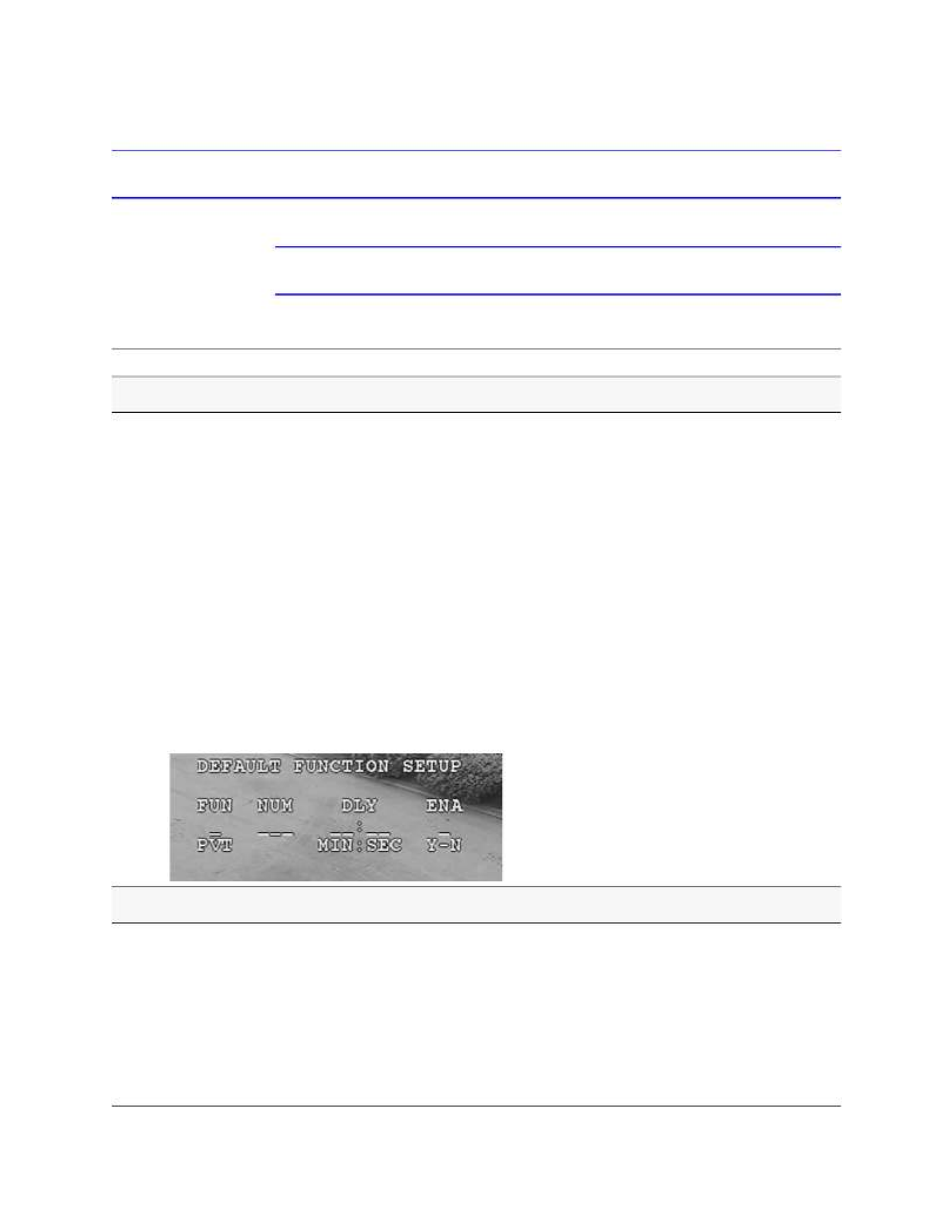
ACUIX PTZ Installation and Configuration Guide
Document 800-03140 Rev A 89
12/08
Configuring Default Functions: Presets and Tours
Note Remember you access the OSD by pressing 90 X Preset.
Task/Action with Default Notes
Setting the Default Function Values
1. Select 3 Control Options X5 Set Default Function X enter
values into each field as required:
a. From the FUN column, select P, V, or T.
This is the function that performs after being idle for the
specified delay time. The function displays on the screen
as PS=preset, PT=preset tour, or MT= mimic tour.
b. In the NUM column, enter the preset or preset tour number.
• If a preset is reserved for a special function; PS = PS
Reserved displays.
• If preset 1 is entered, but not pre programmed, PS =
Does Not Exist displays.
c. In the DLY column, enter the MIN:SEC (minutes:seconds)
of delay before the function is performed.
The maximum delay is 99 minutes and 59 seconds.
d. In the ENA column, select Y to enable or N to disable the
default function.
If the function is programmed, the text
displays. For example, if P (preset) 1 is
entered pre programmed and named, PS
= Entrance Door displays.
Enabling or Disabling the Default Function
1. Select 3 Control Options X5 Set Default Function X
2. Select Enable or Disable as required.
• IF enabled, and the dome is idle for the programmed DLY
(delay) setting, THEN the dome performs the function
(preset, preset tour, or mimic tour) programmed in the
default function setup menu after the programmed delay
with no activity.
• IF disabled, THEN the unit remains at its present position
until a control command is received.
If contacts are present then the dome
automatically acknowledges the current
contact, resets its delay timer, and
processes the next contact in numerical
order. All contacts are processed before
performing the default function.
If motion detection is enabled, then the
default function is automatically disabled.

90
Configuring the ACUIX Dome
Configuring Presets and Preset Tours
Note Presets are also called PreShots on some controllers.
Note Remember you access the OSD by pressing 90 X Preset.
• If an operator runs a preset tour continuously, the dome goes from the last preset to
the first preset. The amount of time the ACUIX takes to go to each preset depends on
the programmed velocity and the distance to the next preset’s pan and tilt
coordinates. The velocity is programmable from 1° to 480° per second.
• The preset tour repeats continuously until an operator manually controls the dome
(pan, tilt, zoom, focus, or iris) or the dome receives a preset, preset tour, mimic tour,
or find home command.
Note If you are using a TDN camera, the focus changes when the IR cut filter is
removed. Therefore, when a preset is programmed during the day it may be
out of focus at night when the IR cut filter is removed. The only way around
this is to have day presets and night presets.
Continuous preset tour operation for extended periods of time (more than eight hours)
is not recommended. Continuous operation results in increased zoom lens wear and
maintenance expense. Similarly, avoid setting auto focus to continuous.
Table 5-5 Preset Title Operation
If: Then:
Preset title is ON The preset title displays on the monitor.
Camera MSG is ON The Camera ID and the letter A are displayed on the
monitor.
An operator sends the dome to
an unprogrammed preset
The message DOES NOT EXIST displays on the
monitor.

ACUIX PTZ Installation and Configuration Guide
Document 800-03140 Rev A 91
12/08
Task/Action with Default Notes
Programming Preset Tours
1. Select 6 Function Programming X .2 Program a Preset Tour
2. Select a preset tour NUM (number) to program.
3. Select each Preset already programmed to use in the preset
tour.
4. Select a Velocity between each preset (1 to 480/s).
The default is 360°/second.
5. Select a Dwell time for how long the dome waits before it goes
to the next preset in the list. Select from 1 to 99 seconds.
6. Select S to save, E to exit or D to delete.
Inserting presets: To insert a preset
between presets, position the cursor on
the second preset and press Focus (+)
to insert a line.
Deleting presets: To delete a preset,
place the cursor on the preset line and
press Focus (-). The entire preset line is
deleted.
Turning Preset Tour Auto Focus ON or OFF
1. Select 3 Control Options .X7 Preset Tour Auto Focus
2. Select:
•OFF (default) to prevent auto focusing during preset tours
and allows the lens to focus based on the stored position.
•ON to auto focus the lens while running a preset tour.
Running Preset Tours Using Special Presets 87-89
1. Select the applicable special preset number:
•87 X Preset to run preset tour 1.
•88 X Preset to run preset tour 2.
•89 X Preset to run preset tour 3.
2. IF the dome is sent to an unprogrammed preset, DOES NOT
EXIST displays on the monitor, otherwise the preset tour starts.
Stopping a Preset Tour
• Take manual control (pan, tilt, zoom, or focus) of the dome.
• Send the dome to a preset.
• Start a mimic tour, a different preset tour, or any other command addressed to that dome.
Program Preset Tour
NUM PRESET VELOCITY DWELL
1 -- --- --
2 -- --- --
3 -- --- --
4 -- --- --
5 -- --- --
6 -- --- --
7 -- --- --
D = Delete E = Exit S = Save

ACUIX PTZ Installation and Configuration Guide
Document 800-03140 Rev A 93
12/08
Configuring Privacy Zones
Note Remember you access the OSD by pressing 90 X Preset.
Note Note the following when configuring privacy zones:
• When a dome is powered up, it automatically starts to find home. When a
privacy zone is enabled, no video is shown during this process and
privacy zones are not recognized until the dome reaches home. Once the
dome finds home, a picture can be viewed on the monitor unless a
privacy zone overlaps with this home setting.
• If a dome is sent to a preset and any portion of a privacy zone would be
visible while traveling to the preset, the video is masked with the box
where any portion of a privacy zone is visible.
• To prevent any privacy zones being visible if the dome loses power, the
video is blanked upon power-up until the unit finds home.

94
Configuring the ACUIX Dome
Table 5-6 Privacy Zone Functions
Task/Action with Default Notes
Programming a Privacy Zone
1. Position the dome so the area to be covered by the privacy
zone is on the monitor.
2. Select 6 Function Programming X 6 Program Privacy Zone.
3. Enter the 4 digit PIN. The default is 1000.
4. Select a privacy zone number between 1 and 24 to assign the
area. Privacy zones are assigned a priority between 1 and 24 in
the order programmed. For example, if user programs Zone 24
before Zone15, Zone 24 is a Priority 1 and Zone 15 is a
Priority 2.
• If a privacy zone is disabled, it does not display on the PTZ
Priority Menu.
• When a privacy zone is enabled, it is assigned the highest
unused priority available.
5. Press Focus Far (-) to switch to PTZ mode to gain control over
the joystick. Adjust the coordinates of the privacy zone as
required using the joystick and moving it up or right to create a
mask/box.
The tilt cannot be greater than 70° and the zoom cannot be
more than 1x.
6. Press Focus Near (+) to switch to menu mode to access the
controller keyboard. Press Iris Open (+) to save the
coordinates.
7. Program another privacy zone or exit.
This menu is available only when using
MAXPRO-mode, VCL, UTP and Pelco P or
D protocols.
Changing the Privacy Zone Mask Color
1. Select 6 Function Programming X 3 Privacy Zone Options
X 3 Privacy Zone Color.
2. Select the color of the mask, Black, Blur or White.
This menu is available only when using
MAXPRO-mode, VCL, UTP and Pelco P or
D protocols.
Assigning or Editing Privacy Zone Priority Order
1. Select 6 Function Programming X 3 Privacy Zone Options
X 1 Change Priv Zone Priority.
2. From the Zone Name or Zone ID columns, select a privacy
zone to edit and assign a different priority number.
• Priority 1 has the highest priority and Priority 24
the lowest no matter the privacy zone number assigned.
That is to say, there is no relation between zone id and
zone priority.
3. In the From field, enter the current priority number, for example,
4.
4. In the To field, enter the new priority number, for example, 1.
The priority order is useful if privacy zones
overlap.
This menu is only available in
MAXPRO-mode, VCL, UTP and Pelco P or
D protocols.
CHANGE PRIV ZONE PRIORITY
PRIORITY PZ_NAME ZONE-ID
1 Privacy 1 1
2 Privacy 2 2
3 Privacy 3 3
Change Priority _-- to --

ACUIX PTZ Installation and Configuration Guide
Document 800-03140 Rev A 95
12/08
Enabling or Disabling Privacy Zones (PZ)
1. Select 6 Function Programming X 3 Privacy Zone Options
X X 2 Enable/Disable PZ
2. Navigate to the Enabled column and select Y (yes) for enable
(default) or N (no) for disable.
• When a privacy zone is enabled, it is assigned the highest
unused priority available.
• If a privacy zone is disabled, the programming is saved, but
the video is not masked when the dome moves into the
programmed privacy zone area.
• This menu is available only when
using MAXPRO-mode, VCL, UTP
and Pelco P or D protocols.
• To move between the rows on the
same page, move the joystick up or
down (MAXPRO-mode, VCL,
VCL-UTC, Pelco P or D).
• To move between pages (if there are
more than six privacy zones) move
the joystick left or right
(MAXPRO-mode, VCL, VCL-UTC,
Pelco P or D).
Deleting Privacy Zones One at a Time
1. Select 6 Function Programming X 3 Privacy Zone Options
X 4 Delete Privacy Zones.
2. Locate and select the applicable privacy zone to delete.
The message Delete Success displays or, if the selected
privacy zone number is not programmed, Does Not Exist
displays.
Existing programming does not have to
be deleted to be reprogrammed. You can
edit the coordinates for an existing mimic
tour, privacy zone, preset, or Sector by
following the applicable programming
procedures
This menu is only available with
MAXPRO-mode, VCL, UTP and Pelco P or
D protocols.
Deleting all Privacy Zones
1. Press 75 .X Preset
The Administrator Login Screen opens.
2. Enter the 4-digit PIN. The default is 1000.
The Password Settings window opens.
3. Select 4 Delete all Privacy Zones.
This menu is only available with
MAXPRO-mode, VCL, UTP and Pelco P or
D protocols.
Table 5-6 Privacy Zone Functions
Task/Action with Default Notes
ENABLE/DISABLE PZONE MENU
ZONE
-ID ZONE
-NAME ENABLED
1 PRIVACY 1 Y
2 PRIVACY 2 Y
3 PRIVACY 3 Y

ACUIX PTZ Installation and Configuration Guide
Document 800-03140 Rev A 97
12/08
Viewing a List of Sectors
• Select 6 Function Programming X 4 List PS/PT/Sectors X3
Sectors.
The list is generated on screen of all
programmed sectors
Deleting a Sector
1. Select 6 Function Programming X 7 Delete
PS/PT/MT/Sectors.
2. Locate and select the applicable sector number.
The message Delete Success displays or if the selected
function and number is not programmed, the message Does
Not Exist displays instead.
Existing programming does not have to
be deleted to be reprogrammed. You can
edit the coordinates for an existing sector
by following the programming procedure
Task/Action with Default Notes

98
Configuring the ACUIX Dome

Document 800-03140 Rev A 99
12/08
6
System Administration and Equipment
Handling
In this section:
•Working with Passwords and PINs, page 99
•Restoring Default Settings or Resetting the Dome or Lens, page 101
•Resetting the Scan, Dome or Camera, page 102
•Changing Dome Address, Protocol, Parity or Baud Rate, page 102
•Sending Common Commands to all Domes, page 103
•Handling and Cleaning Equipment, page 104
Working with Passwords and PINs
Enabling the User or Privacy Zone Login PIN
Note Even if the user or privacy zone login PIN is disabled, a password is still
required to enter the Admin Login/Password Settings menu.
1. Ensure you have manual control of the dome.
2. Press 75 X Preset.
3. Enter the 4-digit PIN. The default is 1000.
4. Select 1 User Login PIN X Enabled or Disabled (default).

100
System Administration and Equipment Handling
Changing a 4-Digit User or Privacy Zone Login PIN
1. Press 75 X Preset.
2. Enter the 4-digit PIN. The default is 1000.
3. Select 2 Change PIN.
4. Enter a new PIN.
5. Re-enter the PIN to verify as above.
• If you enter the wrong 4-digit number, Invalid PIN, try again displays and
the dome returns to the Enter PIN screen.
• If you entered the correct PIN, PIN changed displays and the Password
Settings menu opens.
Recovering an Encrypted User or Privacy Zone Login PIN
1. Press 75 X Preset.
An encrypted PIN number displays on the monitor.
2. Write down the number.
3. Contact Honeywell Technical Support to recover the actual PIN.
Resetting a Privacy Zone Password (Diamond or IntelliBus Only)
Note Up to a 24-alphanumeric characters can be programmed as a password. The
default password is a blank line.
1. Press 75 X X Preset enter the current alphanumeric password.
2. Select 3 Reset Privacyzone Password.
The password is reset to the factory default password, which is blank. To enter a
blank password, press Enter at the password prompt.

ACUIXTM PTZ Installation and Configuration Guide
Document 800-03140 Rev A 101
12/08
Restoring Default Settings or Resetting the Dome or Lens
There are two types of factory defaults that can be restored either directly on the dome via
the OSD Diagnostic Options menu or using a DIP switch. There is an important distinction
between the two.
• Using the OSD menu restores all of the camera and dome configuration settings to
the factory defaults, but DOES NOT delete user programmed configurations (presets,
preset tours, mimic tours, sectors and privacy zones).
• Using DIP switch SW5-7 restores all the settings to defaults and DOES delete user
programmed configurations (presets, preset tours, mimic tours, sectors and privacy
zones).
Restoring Defaults Using the OSD
1. Select 4 Diagnostic Options X .6 Restore Default Settings
2. Select:
• N to cancel.
• Y to continue.
This will restore all user default settings to their default
values displays.
Restoring to Factory Defaults Using a Switch
Note The switch is read only at power up.
1. Locate switch SW5-7.
2. Carefully place the switch in the required position.
• (Default) Select OFF to keep normal operation.
• Select ON to restore factory default settings and delete any user programmed
configurations (presets, preset tours, mimic tours, sectors and privacy zones).
3. After the factory default is restored, set switch back to position to prevent OFF
unwanted deletion of user programmed configurations.

102
System Administration and Equipment Handling
Resetting the Scan, Dome or Camera
Resetting the Scan and Dome
Note Resetting the dome is the same as cycling the power to the dome. It does not
restore the factory defaults but preserves all of the dome setup information.
Once you select this menu option, there is no warning before the reset
begins.
• Select 4 Diagnostics Options X .7 Scan and Dome Reset
Resetting the Camera Lens
• Select 98 X Preset.
Changing Dome Address, Protocol, Parity or Baud Rate
Changing the Address Using a DIP Switch
Note It is recommended for most installations that SW5–8 is kept ON during
normal operation so that the logical address cannot be changed from the
on-screen setup menus.
1. Locate switch SW5 position 8.
2. Carefully place the switch in the required position to set the dome address from
memory.
• (Default) Select ON to force the dome to read the information from the switches.
• Select OFF to allow changes to settings using the OSD.
ACUIXTM PTZ Installation and Configuration Guide
Document 800-03140 Rev A 103
12/08
Changing the Address, Protocol, Parity or Baud Rate Using the OSD
Access to the OSD Is determined by the DIP switch SW5-8 setting. If this switch is set to
OFF, the current address and protocol settings can be viewed but not changed.
1. Select 75 X Preset X
• 1 Change Dome (Camera) address
• 2 Change Protocol
• 3 Change Baud Rate
• 4 Change Parity
2. Select the applicable settings:
• Enter a numerical dome address.
• Select a protocol: Diamond, MAXPRO-mode, , VCL-485 VCL UTC, Pelco P,
Pelco D, IntelliBus.
• Select a baud rate: 600 1200 2400 4800 9600 19200 38400 57600, , , , , , , , or
115200.
• Select a parity: Even, Odd, or None.
Sending Common Commands to all Domes
Special presets 73 and 74 enable and disable the broadcast command receive mode.
When enabled, all domes receive all the commands sent from the controller to any dome
address. For example, an operator might want to standardize the on-screen display (OSD)
language displayed on the monitors for all the domes in the system.
Note This option is not applicable to IntelliBus protocol as this protocol uses a
different addressing mechanism to communicate with domes.
Changing these settings can cause loss of communication between the controller and
the dome. Do not go above the limit of the controller as this may result in you losing
control of the dome.
Only enable the Broadcast Command mode when common settings require changing
and these common settings are for the same value across the network. Otherwise the
dome performs all the commands even if not required or sent to that dome.
Especificaciones del producto
| Marca: | Honeywell |
| Categoría: | Cámara de vigilancia |
| Modelo: | Acuix HDVJNWAC |
¿Necesitas ayuda?
Si necesitas ayuda con Honeywell Acuix HDVJNWAC haz una pregunta a continuación y otros usuarios te responderán
Cámara de vigilancia Honeywell Manuales

23 Septiembre 2024
20 Septiembre 2024
26 Agosto 2024
25 Agosto 2024
24 Agosto 2024
23 Agosto 2024
22 Agosto 2024
22 Agosto 2024
22 Agosto 2024
21 Agosto 2024
Cámara de vigilancia Manuales
- Cámara de vigilancia Sony
- Cámara de vigilancia Samsung
- Cámara de vigilancia Xiaomi
- Cámara de vigilancia Bosch
- Cámara de vigilancia Braun
- Cámara de vigilancia Philips
- Cámara de vigilancia Panasonic
- Cámara de vigilancia Grundig
- Cámara de vigilancia Gigaset
- Cámara de vigilancia JVC
- Cámara de vigilancia Motorola
- Cámara de vigilancia Toshiba
- Cámara de vigilancia Canon
- Cámara de vigilancia Abus
- Cámara de vigilancia Ag Neovo
- Cámara de vigilancia Allnet
- Cámara de vigilancia Alecto
- Cámara de vigilancia Apc
- Cámara de vigilancia Aldi
- Cámara de vigilancia Aluratek
- Cámara de vigilancia Airlive
- Cámara de vigilancia Anker
- Cámara de vigilancia Aritech
- Cámara de vigilancia Acti
- Cámara de vigilancia ACME
- Cámara de vigilancia Edimax
- Cámara de vigilancia Strong
- Cámara de vigilancia Flamingo
- Cámara de vigilancia Hikvision
- Cámara de vigilancia Nedis
- Cámara de vigilancia Thomson
- Cámara de vigilancia Yale
- Cámara de vigilancia Pyle
- Cámara de vigilancia Asus
- Cámara de vigilancia Caliber
- Cámara de vigilancia SereneLife
- Cámara de vigilancia Eminent
- Cámara de vigilancia Avanti
- Cámara de vigilancia Renkforce
- Cámara de vigilancia Overmax
- Cámara de vigilancia Niceboy
- Cámara de vigilancia Sitecom
- Cámara de vigilancia Blaupunkt
- Cámara de vigilancia TP Link
- Cámara de vigilancia Megasat
- Cámara de vigilancia Logitech
- Cámara de vigilancia Manhattan
- Cámara de vigilancia Exibel
- Cámara de vigilancia Ezviz
- Cámara de vigilancia Elro
- Cámara de vigilancia EMOS
- Cámara de vigilancia KlikaanKlikuit
- Cámara de vigilancia Denver
- Cámara de vigilancia DataVideo
- Cámara de vigilancia Schneider
- Cámara de vigilancia Axis
- Cámara de vigilancia Sanyo
- Cámara de vigilancia Vitek
- Cámara de vigilancia Imou
- Cámara de vigilancia Hama
- Cámara de vigilancia Maginon
- Cámara de vigilancia Mitsubishi
- Cámara de vigilancia Velleman
- Cámara de vigilancia Smartwares
- Cámara de vigilancia Profile
- Cámara de vigilancia Marquant
- Cámara de vigilancia Trebs
- Cámara de vigilancia Ednet
- Cámara de vigilancia AVerMedia
- Cámara de vigilancia Eufy
- Cámara de vigilancia Steren
- Cámara de vigilancia Perel
- Cámara de vigilancia Burg-Wachter
- Cámara de vigilancia Lumens
- Cámara de vigilancia Flir
- Cámara de vigilancia Netis
- Cámara de vigilancia Genius
- Cámara de vigilancia Adj
- Cámara de vigilancia Digitus
- Cámara de vigilancia Olympia
- Cámara de vigilancia Uniden
- Cámara de vigilancia Dahua Technology
- Cámara de vigilancia Ion
- Cámara de vigilancia GeoVision
- Cámara de vigilancia Arlo
- Cámara de vigilancia Netgear
- Cámara de vigilancia Nest
- Cámara de vigilancia LevelOne
- Cámara de vigilancia DIO
- Cámara de vigilancia Boss
- Cámara de vigilancia Siedle
- Cámara de vigilancia Ricoh
- Cámara de vigilancia Hive
- Cámara de vigilancia Netatmo
- Cámara de vigilancia Marshall
- Cámara de vigilancia Switel
- Cámara de vigilancia Chacon
- Cámara de vigilancia InFocus
- Cámara de vigilancia Hombli
- Cámara de vigilancia Reolink
- Cámara de vigilancia First Alert
- Cámara de vigilancia UniView
- Cámara de vigilancia Planet
- Cámara de vigilancia ZyXEL
- Cámara de vigilancia Western Digital
- Cámara de vigilancia Clas Ohlson
- Cámara de vigilancia Naxa
- Cámara de vigilancia Powerfix
- Cámara de vigilancia Konig
- Cámara de vigilancia Trevi
- Cámara de vigilancia Foscam
- Cámara de vigilancia BRK
- Cámara de vigilancia Orion
- Cámara de vigilancia Zebra
- Cámara de vigilancia EVE
- Cámara de vigilancia Technaxx
- Cámara de vigilancia D-Link
- Cámara de vigilancia Swann
- Cámara de vigilancia Tenda
- Cámara de vigilancia Xavax
- Cámara de vigilancia Marmitek
- Cámara de vigilancia Minox
- Cámara de vigilancia Delta Dore
- Cámara de vigilancia M-e
- Cámara de vigilancia Lorex
- Cámara de vigilancia Ubiquiti Networks
- Cámara de vigilancia Marshall Electronics
- Cámara de vigilancia Vaddio
- Cámara de vigilancia Gira
- Cámara de vigilancia Jung
- Cámara de vigilancia Interlogix
- Cámara de vigilancia Ring
- Cámara de vigilancia Trendnet
- Cámara de vigilancia DSC
- Cámara de vigilancia Boyo
- Cámara de vigilancia Laserliner
- Cámara de vigilancia Iget
- Cámara de vigilancia CRUX
- Cámara de vigilancia Conceptronic
- Cámara de vigilancia EverFocus
- Cámara de vigilancia Adesso
- Cámara de vigilancia Satel
- Cámara de vigilancia Vivotek
- Cámara de vigilancia Notifier
- Cámara de vigilancia Hawking Technologies
- Cámara de vigilancia Lanberg
- Cámara de vigilancia Friedland
- Cámara de vigilancia Revo
- Cámara de vigilancia Quantum
- Cámara de vigilancia Monoprice
- Cámara de vigilancia Broan
- Cámara de vigilancia Avidsen
- Cámara de vigilancia Furrion
- Cámara de vigilancia Beafon
- Cámara de vigilancia SPC
- Cámara de vigilancia Stabo
- Cámara de vigilancia Crestron
- Cámara de vigilancia Chuango
- Cámara de vigilancia ORNO
- Cámara de vigilancia ETiger
- Cámara de vigilancia INSTAR
- Cámara de vigilancia Grandstream
- Cámara de vigilancia Provision ISR
- Cámara de vigilancia Monacor
- Cámara de vigilancia Logilink
- Cámara de vigilancia Aqara
- Cámara de vigilancia Moxa
- Cámara de vigilancia Advantech
- Cámara de vigilancia Digital Watchdog
- Cámara de vigilancia Ferguson
- Cámara de vigilancia Ganz
- Cámara de vigilancia MEE Audio
- Cámara de vigilancia Kwikset
- Cámara de vigilancia Elmo
- Cámara de vigilancia Intellinet
- Cámara de vigilancia Ebode
- Cámara de vigilancia Oplink
- Cámara de vigilancia Kerbl
- Cámara de vigilancia Dorr
- Cámara de vigilancia Sonic Alert
- Cámara de vigilancia Linear PRO Access
- Cámara de vigilancia BirdDog
- Cámara de vigilancia AVer
- Cámara de vigilancia Summer Infant
- Cámara de vigilancia SMC
- Cámara de vigilancia Topica
- Cámara de vigilancia Kogan
- Cámara de vigilancia Iiquu
- Cámara de vigilancia Speco Technologies
- Cámara de vigilancia Verint
- Cámara de vigilancia ZKTeco
- Cámara de vigilancia Brinno
- Cámara de vigilancia Raymarine
- Cámara de vigilancia Rostra
- Cámara de vigilancia Caddx
- Cámara de vigilancia Spyclops
- Cámara de vigilancia Schwaiger
- Cámara de vigilancia EKO
- Cámara de vigilancia Inovonics
- Cámara de vigilancia Kguard
- Cámara de vigilancia Woonveilig
- Cámara de vigilancia Mobi
- Cámara de vigilancia V-Tac
- Cámara de vigilancia Surveon
- Cámara de vigilancia Hollyland
- Cámara de vigilancia Epcom
- Cámara de vigilancia EVOLVEO
- Cámara de vigilancia Indexa
- Cámara de vigilancia AViPAS
- Cámara de vigilancia Kramer
- Cámara de vigilancia Lutec
- Cámara de vigilancia Whistler
- Cámara de vigilancia Hanwha
- Cámara de vigilancia ClearView
- Cámara de vigilancia VideoComm
- Cámara de vigilancia IMILAB
- Cámara de vigilancia 3xLOGIC
- Cámara de vigilancia Pelco
- Cámara de vigilancia EtiamPro
- Cámara de vigilancia Inkovideo
- Cámara de vigilancia Pentatech
- Cámara de vigilancia Weldex
- Cámara de vigilancia SecurityMan
- Cámara de vigilancia Brilliant
- Cámara de vigilancia Lindy
- Cámara de vigilancia Canyon
- Cámara de vigilancia CNB Technology
- Cámara de vigilancia Tapo
- Cámara de vigilancia Aigis
- Cámara de vigilancia Exacq
- Cámara de vigilancia Brickcom
- Cámara de vigilancia Laxihub
- Cámara de vigilancia Securetech
- Cámara de vigilancia EFB Elektronik
- Cámara de vigilancia Ernitec
- Cámara de vigilancia NetMedia
- Cámara de vigilancia Videotec
- Cámara de vigilancia Illustra
- Cámara de vigilancia Atlona
- Cámara de vigilancia AVMATRIX
- Cámara de vigilancia Nivian
- Cámara de vigilancia Arenti
- Cámara de vigilancia E-bench
- Cámara de vigilancia Blow
- Cámara de vigilancia Syscom
- Cámara de vigilancia Tecno
- Cámara de vigilancia Night Owl
- Cámara de vigilancia Guardzilla
- Cámara de vigilancia Astak
- Cámara de vigilancia Blink
- Cámara de vigilancia Milestone Systems
- Cámara de vigilancia Zavio
- Cámara de vigilancia Campark
- Cámara de vigilancia IPX
- Cámara de vigilancia Dedicated Micros
- Cámara de vigilancia Hamlet
- Cámara de vigilancia Equip
- Cámara de vigilancia Annke
- Cámara de vigilancia AVTech
- Cámara de vigilancia Qoltec
- Cámara de vigilancia Approx
- Cámara de vigilancia Digimerge
- Cámara de vigilancia Y-cam
- Cámara de vigilancia Alfatron
- Cámara de vigilancia Feelworld
- Cámara de vigilancia KJB Security Products
- Cámara de vigilancia Wisenet
- Cámara de vigilancia BZBGear
- Cámara de vigilancia WyreStorm
- Cámara de vigilancia Infortrend
- Cámara de vigilancia Epiphan
- Cámara de vigilancia HiLook
- Cámara de vigilancia Mach Power
- Cámara de vigilancia Compro
- Cámara de vigilancia Aida
- Cámara de vigilancia Ikegami
- Cámara de vigilancia Accsoon
- Cámara de vigilancia Vimtag
- Cámara de vigilancia Sonoff
- Cámara de vigilancia Gewiss
- Cámara de vigilancia Alula
- Cámara de vigilancia Insteon
- Cámara de vigilancia Costar
- Cámara de vigilancia ALC
- Cámara de vigilancia Security Labs
- Cámara de vigilancia Comtrend
- Cámara de vigilancia Seneca
- Cámara de vigilancia Avigilon
- Cámara de vigilancia American Dynamics
- Cámara de vigilancia Vosker
- Cámara de vigilancia Sentry360
- Cámara de vigilancia Owltron
- Cámara de vigilancia Petcube
- Cámara de vigilancia Enabot
- Cámara de vigilancia Luis Energy
- Cámara de vigilancia Sir Gawain
- Cámara de vigilancia VisorTech
- Cámara de vigilancia Atlantis Land
- Cámara de vigilancia B & S Technology
- Cámara de vigilancia I3International
- Cámara de vigilancia IDIS
- Cámara de vigilancia Promise Technology
- Cámara de vigilancia Ecobee
- Cámara de vigilancia Turing
- Cámara de vigilancia Qian
- Cámara de vigilancia Wasserstein
- Cámara de vigilancia Qolsys
- Cámara de vigilancia Control4
- Cámara de vigilancia Milesight
- Cámara de vigilancia GVI Security
- Cámara de vigilancia Conbrov
- Cámara de vigilancia HuddleCamHD
- Cámara de vigilancia Setti+
- Cámara de vigilancia Defender
- Cámara de vigilancia Mobotix
- Cámara de vigilancia IOIO
- Cámara de vigilancia BIRDFY
- Cámara de vigilancia I-PRO
- Cámara de vigilancia DVDO
- Cámara de vigilancia TCP
Últimos Cámara de vigilancia Manuales
27 Octubre 2024
27 Octubre 2024
27 Octubre 2024
27 Octubre 2024
27 Octubre 2024
27 Octubre 2024
27 Octubre 2024
27 Octubre 2024
27 Octubre 2024
27 Octubre 2024