Asus RS720-E7/RS12 Manual de Usario
Lee a continuación 📖 el manual en español para Asus RS720-E7/RS12 (189 páginas) en la categoría servidor. Esta guía fue útil para 2 personas y fue valorada con 4.5 estrellas en promedio por 2 usuarios
Página 1/189

2U Rackmount Server
RS720-E7/RS12
RS720-E7/RS12-E
User Guide

ii
Copyright © 2012 ASUSTeK COMPUTER INC. All Rights Reserved.
No part of this manual, including the products and software described in it, may be reproduced, transmitted,
transcribed, stored in a retrieval system, or translated into any language in any form or by any means,
except documentation kept by the purchaser for backup purposes, without the express written permission
of ASUSTeK COMPUTER INC. (“ASUS”).
ASUS provides this manual “as is” without warranty of any kind, either express or implied, including but not
limited to the implied warranties or conditions of merchantability or tness for a particular purpose. In no
event shall ASUS, its directors, ofcers, employees, or agents be liable for any indirect, special, incidental,
or consequential damages (including damages for loss of prots, loss of business, loss of use or data,
interruption of business and the like), even if ASUS has been advised of the possibility of such damages
arising from any defect or error in this manual or product.
Specications and information contained in this manual ae furnished for informational use only, and are
subject to change at any time without notice, and should not be construed as a commitment by ASUS.
ASUS assumes no responsibility or liability for any errors or inaccuracies that may appear in this manual,
including the products and software described in it.
Product warranty or service will not be extended if: (1) the product is repaired, modied or altered, unless
such repair, modication of alteration is authorized in writing by ASUS; or (2) the serial number of the
product is defaced or missing.
Products and corporate names appearing in this manual may or may not be registered trademarks or
copyrights of their respective companies, and are used only for identication or explanation and to the
owners’ benet, without intent to infringe.
E7520
Revised Edition V2
June 2012

iii
Contents
Notices ........................................................................................................ vii
Safety information .................................................................................... viii
About this guide ......................................................................................... ix
Chapter 1: Product introduction
1.1 System package contents ........................................................... 1-2
1.2 Serial number label ......................................................................1-2
1.3 Systemspecications .................................................................1-3
1.4 Front panel features .....................................................................1-5
1.5 Rear panel features ......................................................................1-6
1.6 Internal features ...........................................................................1-7
1.7 LED information ...........................................................................1-8
1.7.1 Front panel LEDs ............................................................1-8
1.7.2 LAN (RJ-45) LEDs ..........................................................1-9
1.7.3 HDD status LED ..............................................................1-9
Chapter 2: Hardware setup
2.1 Chassis cover ............................................................................... 2-2
2.2 Central Processing Unit (CPU) ...................................................2-3
2.2.1 Installing the CPU ...........................................................2-3
2.2.2 Installing the CPU heatsink and airduct ..........................2-8
2.3 System memory .........................................................................2-10
2.3.1 Overview .......................................................................2-10
2.3.2 Memory Congurations .................................................2-10
2.3.3 Installing a DIMM ..........................................................2-12
2.4 Hard disk drives .........................................................................2-13
2.5 Expansion slots ..........................................................................2-15
2.5.1 Installing an expansion card .........................................2-15
2.5.2 Conguring an expansion card .....................................2-16
2.5.3 Interrupt assignments ...................................................2-16
2.5.4 PCI Express x16 slots (x16 link) ...................................2-17
2.5.5 PCI Express x16 slot (x8 link) .......................................2-17
2.5.6 PIKE slot .......................................................................2-17
2.6 Cable connections .....................................................................2-18
2.7 SATA/SAS backplane cabling ...................................................2-19
2.8 Removable/optional components .............................................2-21
2.8.1 System fans ..................................................................2-21

iv
Contents
2.8.2 Redundant power supply module 2-22 .................................
2.8.3 Installing ASUS PIKE RAID card ..................................2-23
2.8.4 Installing ASMB6 series management board(Default) ..2-24
Chapter 3: Installation options
3.1 Installing friction rail kit items .................................................... 3-2
3.1.1 Attaching the xing latches to the server ........................3-2
3.1.2 Mounting the server to the rack ......................................3-5
Chapter 4: Motherboard information
4.1 Motherboard layouts .................................................................... 4-2
4.2 Jumpers ........................................................................................4-4
4.3 Internal connectors ......................................................................4-8
Chapter 5: BIOS Setup
5.1 Managing and updating your BIOS ............................................ 5-2
5.1.1 ASUS CrashFree BIOS 3 utility ......................................5-2
5.1.2 ASUS EZ Flash 2 Utility ..................................................5-3
5.1.3 BUPDATER utility............................................................ 5-4
5.2 BIOS setup program ....................................................................5-6
5.2.1 BIOS menu screen ..........................................................5-7
5.2.2 Menu bar .........................................................................5-7
5.2.3 Menu items .....................................................................5-8
5.2.4 Submenu items ...............................................................5-8
5.2.5 Navigation keys ...............................................................5-8
5.2.6 General help ...................................................................5-8
5.2.7 Conguration elds .........................................................5-8
5.2.8 Pop-up window ...............................................................5-8
5.2.9 Scroll bar .........................................................................5-8
5.3 Main menu ....................................................................................5-9
5.3.1 System Date ..................................................................5-9
5.3.2 System Time ..................................................................5-9
5.4 Advanced menu .........................................................................5-10
5.4.1 CPU Conguration ........................................................5-10
5.4.2 CPU Power Management Conguration .......................5-12
5.4.3 Chipset Conguration ...................................................5-14
5.4.4 PCH SATA Conguration ..............................................5-20

v
Contents
5.4.5 PCH SCU SAS Conguration ....................................... 15-2
5.4.6 PCI Subsystem Settings ...............................................5-22
5.4.7 Onboard LAN Conguration ..........................................5-25
5.4.8 Intel TXT(LT-SX) Conguration .....................................5-26
5.4.9 USB Conguration ........................................................5-27
5.4.10 Trusted Computing ........................................................5-28
5.4.11 ACPI Settings ................................................................5-29
5.4.12 WHEA Conguration .....................................................5-30
5.4.13 APM setting ...................................................................5-30
5.4.14 Serial Port Console Redirection ....................................5-31
5.4.15 ME Subsystem ..............................................................5-34
5.4.16 Legacy Devices Conguration ......................................5-34
5.4.17 Runtime Error Logging ..................................................5-35
5.5 Server Mgmt menu .....................................................................5-36
5.5.1 System Event Log .........................................................5-37
5.5.2 BMC network conguration ...........................................5-38
5.6 Event Logs menu .......................................................................5-39
5.6.1 Change Smbios Event Log Settings .............................5-39
5.7 Boot menu ..................................................................................5-41
5.8 Monitor menu .............................................................................5-43
5.9 Security menu ............................................................................5-44
5.10 Tool menu ...................................................................................5-45
5.11 Exit menu ....................................................................................5-46
Chapter6: RAIDconguration
6.1 Setting up RAID ............................................................................ 6-2
6.1.1 RAID denitions ..............................................................6-2
6.1.2 Installing hard disk drives ................................................6-2
6.1.3 RAID controller selection ................................................6-3
6.1.4 Setting the RAID item in BIOS ........................................6-3
6.2 LSISoftwareRAIDCongurationUtility ...................................6-4
6.2.1 Creating a RAID set ........................................................6-5
6.2.2 Adding or viewing a RAID conguration ........................
6-11
6.2.3 Initializing the virtual drives ...........................................6-12
6.2.4 Rebuilding failed drives .................................................6-16
6.2.5 Checking the drives for data consistency .....................6-18

vi
Contents
6.2.6 Deleting a RAID conguration ....................................... 16-2
6.2.7 Selecting the boot drive from a RAID set ......................6-22
6.2.8 Enabling WriteCache ....................................................6-23
6.3 Intel® Rapid Storage Technology enterprise SCU/SATA Option
ROM Utility ..................................................................................6-24
6.3.1 Creating a RAID set ......................................................6-26
6.3.2 Creating a Recovery set ...............................................6-27
6.3.3 Deleting a RAID set ......................................................6-29
6.3.4 Resetting disks to Non-RAID ........................................6-30
6.3.5 Exiting the Intel® Rapid Storage Technology utility ........ 6-31
6.3.6 Rebuilding the RAID .....................................................6-31
6.3.7 Setting the Boot array in the BIOS Setup Utility ............6-33
6.4 Intel® Rapid Storage Technology enterprise Utility (Windows) 6-34
6.4.1 Creating a RAID set ......................................................6-35
6.4.2 Change Volume Type ....................................................6-37
6.4.3 Delete volume ...............................................................6-38
6.4.4 Preferences ...................................................................6-39
Chapter 7: Driver installation
7.1 RAID driver installation ............................................................... 7-2
7.1.1 Creating a RAID driver disk ............................................7-2
7.1.2 Installing the RAID controller driver ................................7-5
7.2 Intel® chipset device software installation ............................... 7-14
7.3 Intel@ Network Connections Software installation.................. 7-16
7.4 VGA driver installation............................................................... 7-19
7.5 Intel® C600 Series Chipset SAS RAID (SATA mode) Drivers .. 7-22
7.6 Microsoft .NET Framework 3.5 SP1 ..........................................7-23
7.7 Intel® Rapid Storage Technology enterprise 3.0 installation . 7-24
7.8 Intel® I350 Gigabit Adapters Driver installation ....................... 7-27
7.9 Management applications and utilities installation ................7-31
7.9.1 Running the support DVD .............................................7-31
7.9.2 Drivers menu .................................................................7-31
7.9.3 Utilities menu ................................................................7-32
7.9.4 Make disk menu ............................................................7-32
7.9.5 Contact information .......................................................7-32
ASUS contact information .......................................................................A-1

vii
Notices
Federal Communications Commission Statement
This device complies with Part 15 of the FCC Rules. Operation is subject to the
following two conditions:
• This device may not cause harmful interference, and
• This device must accept any interference received including interference that
may cause undesired operation.
This equipment has been tested and found to comply with the limits for a Class
B digital device, pursuant to Part 15 of the FCC Rules. These limits are designed
to provide reasonable protection against harmful interference in a residential
installation. This equipment generates, uses and can radiate radio frequency
energy and, if not installed and used in accordance with manufacturer’s instructions,
may cause harmful interference to radio communications. However, there is no
guarantee that interference will not occur in a particular installation. If this equipment
does cause harmful interference to radio or television reception, which can be
determined by turning the equipment off and on, the user is encouraged to try to
correct the interference by one or more of the following measures:
• Reorient or relocate the receiving antenna.
• Increase the separation between the equipment and receiver.
• Connect the equipment to an outlet on a circuit different from that to which the
receiver is connected.
• Consult the dealer or an experienced radio/TV technician for help.
Canadian Department of Communications Statement
This digital apparatus does not exceed the Class A limits for radio noise emissions
from digital apparatus set out in the Radio Interference Regulations of the
Canadian Department of Communications.
This Class A digital apparatus complies with Canadian ICES-003.
WARNING! The use of shielded cables for connection of the monitor to the
graphics card is required to assure compliance with FCC regulations. Changes
or modications to this unit not expressly approved by the party responsible for
compliance could void the user’s authority to operate this equipment.
REACH Information
Complying with the REACH (Registration, Evaluation, Authorization, and Restriction
of Chemicals) regulatory framework, we publish the chemical substances in our
products at ASUS REACH website at http://green.asus.com/english/REACH.htm.

x
References
Refer to the following sources for additional information, and for product and
software updates.
1. ASUS Server Web-based Management (ASWM) user guide
This manual tells how to set up and use the proprietary ASUS server
management utility.
2. ASUS websites
The ASUS websites worldwide provide updated information for all ASUS
hardware and software products. Refer to the ASUS contact information.
Conventions
To ensure that you perform certain tasks properly, take note of the following
symbols used throughout this manual.
Typography
Bold text Indicates a menu or an item to select.
Italics
Used to emphasize a word or a phrase.
<Key> Keys enclosed in the less-than and greater-than
sign means that you must press the enclosed key.
Example: <Enter> means that you must press
the Enter or Return key.
<Key1+Key2+Key3> If you must press two or more keys simultaneously,
the key names are linked with a plus sign (+).
Example: <Ctrl+Alt+Del>
Command Means that you must type the command
exactly as shown, then supply the required
item or value enclosed in brackets.
Example: At the DOS prompt, type the
command line: format A:/S
DANGER/WARNING: Information to prevent injury to yourself when
trying to complete a task.
Information to prevent damage to the components when CAUTION:
trying to complete a task.
: Tips and additional information to help you complete a task.NOTE
IMPORTANT: Instructions that you MUST follow to complete a task.

This chapter describes the general
features of the chassis kit. It includes
sections on front panel and rear panel
specications.
Chapter 1
Product introduction
Chapter 1: Product introduction1-2
*ASUS System Web-based Management
If any of the above items is damaged or missing, contact your retailer.
1.1 System package contents
Check your system package for the following items.
Model Name RS720-E7/RS12; RS720-E7/RS12-E
Chassis ASUS Rackmount ChassisR20D 2U
Motherboard ASUS Z9PE-D16 Server Board
Component 1 x 770W Redundant Power Supply
1 x SATA HDD Backplane (RS720-E7/RS12)
1 x SATA/SAS HDD Backplane with expander (RS720-E7/RS12-E)
12 x hot-swap HDD trays
1 x Front I/O Shield
1 x Front USB Board
4 x System Fans (80 x 38mm)
1 x Redundant Power Supply Distribution Board (PDB-R20A)
1 x Air Duct
Accessories 1 x RS720-E7/RS12; RS720-E7/RS12-E User’s Guide
1 x ASWM Enterprise User’s Guide
1 x RS720-E7/RS12; RS720-E7/RS12-E Support DVD
1 x Bag of Screws
1 x ASWM Enterprise DVD
1 x ASMB6 Series DVD
1 x ASMB6 User’s Guide
2 x AC Power Cable
1 x Friction Rail Kit
1 x Air Duct
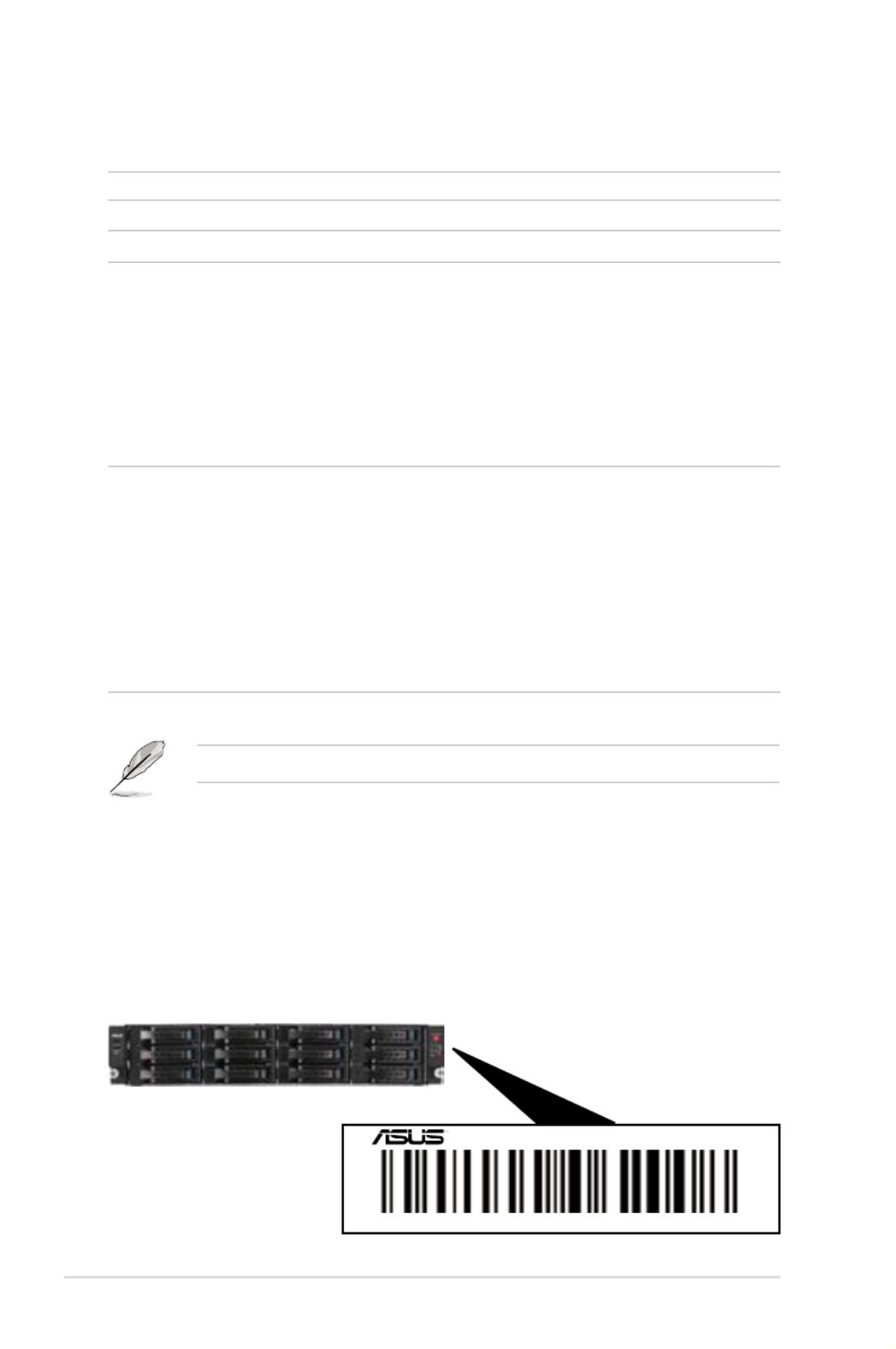
1.2 Serial number label
Before requesting support from the ASUS Technical Support team, you must
take note of the product’s serial number containing 14 characters such as
xxS0xxxxxxxxxx. See the gure below.
With the correct serial number of the product, ASUS Technical Support team
members can then offer a quicker and satisfying solution to your problems.
xxS0xxxxxxxxxx
RS720-E7/RS12

ASUS RS720-E7/RS12; RS720-E7/RS12-E 1-3
1.3 Systemspecications
The ASUS RS720-E7/RS12 and RS720-E7/RS12-E feature the ASUS Z9PE-D16
server board. The server supports Intel® LGA2011 Xeon ® series processors, plus
other latest technologies through the chipsets onboard.
(continued on the next page)
Model Name RS720-E7/RS12 RS720-E7/RS12-E
Processor / System Bus
2 x Intel ® LGA 2011
Intel®
Xeon ® E5-2600 Processor Family
QPI 6.4 / 7.2 / 8.0 GT/s
Core Logic Intel®
C602-A
ASUS Features
Smart Fan √
ASWM
Enterprise √
Memory
Total Slots 16 DDR3 DIMM Slots (4-channel per CPU, 8 DIMMs per CPU)
Capacity
Maximum up to 128GB (UDIMM)
Maximum up to 512GB (RDIMM)
Maximum up to 512GB (LRDIMM)
Memory Type
DDR3 800/1066/1333/1600 RDIMM
DDR3 1066/1333 ECC UDIMM/Non-ECC UDIMM
DDR3 1066/1333 LR-DIMM
Memory Size
1GB, 2GB, 4GB, 8GB, 16GB and 32GB* (RDIMM)
1GB, 2GB, 4GB and 8GB* (UDIMM)
8GB, 16GB and 32GB* (LRDIMM)
Expansion Slots
Total PCI/PCI-X/
PCI-E Slots 6
Slot Type
Low-prole slots:
- Slot 1: PCI-E x16 (X8 Gen3 link, MIO supported, White,
from CPU 1)
- Slot 2: PCI-E x16 (X16 Gen3 link, Auto switch to p13-x8 link if
PCIE 1 is occupied, White, from CPU 1)
- Slot 3: PCI-E x16 (X16 Gen3 link, Black, from CPU 2)
- Slot 4: PCI-E x16 (X16 Gen3 link, White, from CPU 1)
- Slot 5: PCI-E x16 (X16 Gen3 link, Black, from CPU 2)
- Slot 6: PCI-E x16 (X8 Gen3 link, Black, from CPU 2)
Additional Slot 1 x PIKE Slot for Storage expansion (White, from CPU 1)
Storage SATA Controller
Intel®
C602-A :
<AHCI>
2 SATA 6Gb/s ports; 4 SATA
3Gb/s ports
Intel®
RSTe (for Windows
only)
(Support software RAID 0,
1, 10 & 5)
LSI® MegaRAID (for Linux/
Windows)
(Support software RAID 0,
1, 10)
N/A

ASUS RS720-E7/RS12; RS720-E7/RS12-E 1-5
1.4 Front panel features
The barebone server displays a simple yet stylish front panel with easily accessible
features. The power and reset buttons, LED indicators, optical drive, and two USB
ports are located on the front panel.
Refer to section for the LED descriptions.1.7.1 Front panel LEDs
USB ports Power button
Front panel
LEDs
Location
switch
Reset button
USB ports Power button
Front panel
LEDs
Location
switch
Reset button
HDD 1 (SAS/SATA) HDD 2 (SAS/SATA) HDD 3 (SAS/SATA) HDD 4 (SAS/SATA)
HDD 5 (SAS/SATA) HDD 6 (SAS/SATA) HDD 7 (SAS/SATA) HDD 8 (SAS/SATA)
HDD 9 (SATA) HDD 10 (SATA) HDD 11 (SATA) HDD 12 (SATA)
RS720-E7/RS12
RS720-E7/RS12-E
HDD 9 (SAS/SATA) HDD 10 (SAS/SATA) HDD 11 (SAS/SATA) HDD 12 (SAS/SATA)
HDD 1 (SAS/SATA) HDD 2 (SAS/SATA) HDD 3 (SAS/SATA) HDD 4 (SAS/SATA)
HDD 5 (SAS/SATA) HDD 6 (SAS/SATA) HDD 7 (SAS/SATA) HDD 8 (SAS/SATA)

Chapter 1: Product introduction1-6
• The ports for the PS/2 keyboard, PS/2 mouse, USB, VGA, and Gigabit LAN
do not appear on the rear panel if motherboard is not present.
• *The port is for ASUS ASMB6-iKVM controller card only.
1.5 Rear panel features
The rear panel includes the expansion slots, system power socket, and rear fans.
The middle part includes the I/O shield with openings for the rear panel connectors
on the motherboard.
PS/2 keyboard port
USB ports
LAN port 1
VGA port
6 Expansion slots
LAN port 2
Power cord
connector
PS/2 mouse port
Redundant power
supply
DM_LAN 1 port *
LAN port 3
LAN port 4

ASUS RS720-E7/RS12; RS720-E7/RS12-E 1-7
1.6 Internal features
The barebone server includes the basic components as shown.
The barebone server does not include a oppy disk drive. Connect a USB oppy
disk drive to any of the USB ports on the front or rear panel if you need to use a
oppy disk.
*WARNING
HAZARDOUS MOVING PARTS
KEEP FINGERS AND OTHER BODY PARTS AWAY
1. Power supply and power
fan
2. ASUS Z9PE-D16 Server
Board
3. System fans
4. SATA/SAS backplane
(hidden)
5. Hot-swap HDD tray 1–
12 (SAS and SATA)
6. Front USB I/O Board
(USB-R20A)
7. Front LED Board (FPB-
R20A)
A protection lm is pre-attached to the front cover before shipping. Please
remove the protection lm before turning on the system for proper heat
dissipation.
1
2
3
5
67
4

Chapter 1: Product introduction1-8
1.7 LED information
1.7.1 Front panel LEDs
Message LED
LAN2/4 LED
HDD Access LED
LAN1/3 LED
Power LED
Location LED
LED Icon Display
status Description
Power LED ON System power ON
HDD
Access
LED
OFF No activity
Blinking Read/write data into the HDD
Message
LED
OFF System is normal; no incoming event
ON
1. Without ASMB6-iKVM installed: CPU over-heated
2. With ASMB6-iKVM installed: a hardware monitor event is
indicated
Location
LED
OFF Normal status
ON Location switch is pressed (Press the location switch again to
turn off)
LAN LEDs
OFF No LAN connection
Blinking LAN is transmitting or receiving data
ON LAN connection is present

ASUS RS720-E7/RS12; RS720-E7/RS12-E 1-9
1.7.3 HDD status LED
SATA/SAS HDD LED Description
HDD Activity LED (Green)
OFF HDD not present
ON HDD present, no activity
Blinking 1. Read/write data from/into the SATA/SAS HDD
2. Locating (blinking with the HDD status LED)
HDD Status LED (Red)
OFF HDD not present
ON HDD has failed and should be swapped immediately
Blinking 1. RAID rebuilding
2. Locating (blinking with the HDD activity LED)
1.7.2 LAN (RJ-45) LEDs
ACT/LINK LED SPEED LED
Status Description Status Description
OFF No link OFF 10 Mbps connection
GREEN ORANGE 100 Mbps connectionLinked
BLINKING GREEN 1 Gbps connectionData activity
SPEED LED
ACT/LINK LED
HDD Activity LED (Green)
HDD Status LED (Red)

Chapter 2: Hardware setup2-2
2.1 Chassis cover
2. Firmly hold the cover and slide it
toward the rear panel for about half
an inch until it is disengaged from
the chassis.
3. Lift the cover from the chassis.
1. Loosen the two thumbscrews on the rear panel to release the rear cover from
the chassis.
Removing the rear cover
Thumbscrews
1/2 inch distance

2-3ASUS RS720-E7/RS12; RS720-E7/RS12-E
2.2.1 Installing the CPU
To install a CPU:
1. Locate the CPU socket on the motherboard.
2.2 Central Processing Unit (CPU)
The motherboard comes with a surface mount LGA2011 socket designed for the
Intel® Xeon E5-2600 family processor.
• Upon purchase of the motherboard, ensure that the PnP cap is on
the socket and the socket contacts are not bent. Contact your retailer
immediately if the PnP cap is missing, or if you see any damage to the PnP
cap/socket contacts/motherboard components. ASUS will shoulder the cost
of repair only if the damage is shipment/transit-related.
• Keep the cap after installing the motherboard. ASUS will process Return
Merchandise Authorization (RMA) requests only if the motherboard comes
with the cap on the LGA2011 socket.
• The product warranty does not cover damage to the socket contacts
resulting from incorrect CPU installation/removal, or misplacement/loss/
incorrect removal of the PnP cap.
Before installing the CPU, ensure that the socket box is facing towards you and
the load lever is on your left.

Chapter 2: Hardware setup2-4
2. Press the left load lever with your
thumb (A), then move it to the left
(B) until it is released from the
retention tab.
To prevent damage to the socket
pins, do not remove the PnP cap
unless you are installing a CPU.
B
A
E
D
C
4. Press the right load lever with your
thumb (C), then move it to the right
(D) until it is released from the
retention tab. Lift the load lever in
the direction of the arrow (E).
3. Slightly lift the load lever in the
direction of the arrow.
Load lever
Chapter 2: Hardware setup2-8
2. Twist each of the four screws with
a Philips (cross) screwdriver just
enough to attach the heatsink to
the motherboard. When the four
screws are attached, tighten them
one by one to completely secure
the heatsink.
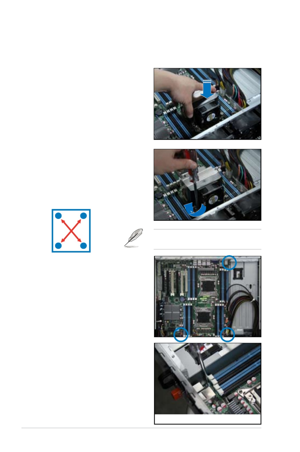
2.2.2 Installing the CPU heatsink and airduct
To install the CPU heatsink:
1. Place the heatsink on top of the
installed CPU, ensuring that the four
fasteners match the holes on the
motherboard.
To install the airduct:
1. Locate the three screws on the
motherboard and remove the three
screws.
Tighten the four heatsink screws in a
diagonal sequence.
A B
BA
2. Remove the three screws from
motherboard.

Chapter 2: Hardware setup2-10
2.3 System memory
2.3.1 Overview
The motherboard comes with eight (per CPU) Double Data Rate 3 (DDR3) Dual
Inline Memory Modules (DIMM) sockets.
2.3.2 MemoryCongurations
You may install 2GB, 4GB, 8GB, and 16GB RDIMMs or 2GB, 4GB and 8GB* with
ECC/Non-ECC UDIMMs or 8GB, 16GB and 32GB* LR-DIMMs into the DIMM
sockets using the memory congurations in this section.

2-11ASUS RS720-E7/RS12; RS720-E7/RS12-E
• Always install DIMMs with the same CAS latency. For optimum
compatibility, we recommend that you obtain memory modules from the
same vendor. Refer to the Qualied Vendors List on the ASUS web site.
• You may install varying memory sizes in Channel A, Channel B and
Channel C. The system maps the total size of the lower-sized channel for
the dual-channel or triple-channel conguration. Any excess memory from
the higher-sized channel is then mapped for single-channel operation.
• Due to the memory address limitation on 32-bit Windows OS, when you
install 4GB or more memory on the motherboard, the actual usable memory
for the OS can be about 3GB or less. For effective use of memory, we
recommend that you do any of the following:
• Use a maximum of 3GB system memory if you are using a 32-bit Windows
OS.
• Install a 64-bit Windows OS when you want to install 4GB or more on
the motherboard. For more details, refer to the Microsoft® support site at
http://support.microsoft.com/kb/929605/en-us.
• This motherboard does not support DIMMs made up of 256 Mb (32MB)
chips or less (Memory chip capacity counts in Megabit, 8 Megabit/Mb = 1
Megabyte/MB).
Memory population table
CPU1Conguration
A2 A1 B2 B1 C2 C1 D2 D1
1 DIMM
2 DIMMs
4 DIMMs
8 DIMMs
CPU1+CPU2Conguration
A2 A1 B2 B1 C2 C1 D2 D1 E2 E1 F2 F1 G2 G1 H2 H1
1 DIMM
2 DIMMs
4 DIMMs
8 DIMMs
12 DIMMs
16 DIMMs

Chapter 2: Hardware setup2-12
2.3.3 Installing a DIMM
3. Hold the DIMM by both of its ends,
then insert the DIMM vertically
into the socket. Apply force to both
ends of the DIMM simultaneously
until the retaining clip snaps back
into place, and the DIMM cannot
be pushed in any further to ensure
proper sitting of the DIMM. Locked Retaining Clip
3
1. Unlock a DIMM socket by pressing
the retaining clip outward.
2. Align a DIMM on the socket
such that the notch on the DIMM
matches the DIMM slot key on the
socket.
Unlocked retaining clip
DIMM notch
2
1
DIMM slot key
1. Press the retaining clip outward to
unlock the DIMM.
2. Remove the DIMM from the socket.
1
2
Removing a DIMM from a single clip DIMM socket
• To install two or more DIMMs, refer to the user guide bundled in the
motherboard package.
• Refer to the user guide for qualied vendor lists of the memory modules.
Support the DIMM lightly with your ngers when pressing the retaining clips.
The DIMM might get damaged when it ips out with extra force.
Always insert the DIMM into the socket VERTICALLY to prevent DIMM notch
damage.
A DIMM is keyed with a notch so that it ts in only one direction. DO NOT force
a DIMM into a socket in the wrong direction to avoid damaging the DIMM.

2-13ASUS RS720-E7/RS12; RS720-E7/RS12-E
2.4 Hard disk drives
The hard disk drive installed on the drive tray connects to the motherboard SATA/
SAS ports via the SATA/SAS backplane.
To install a hot-swap SATA/SAS HDD:
1. Release a drive tray by pushing the
spring lock to the right, then pulling
the tray lever outward. The drive tray
ejects slightly after you pull out the
lever.
spring lock
2. Firmly hold the tray lever and pull
the drive tray out of the bay.
3. Take note of the drive tray holes.
Each side has three holes to t
different types of hard disk drives.
Use two screws on each side to
secure the hard disk drive.
4. Place a SATA/SAS hard disk drive
on the tray, then secure it with four
screws.

Chapter 2: Hardware setup2-14
5. Carefully insert the drive tray and
push it all the way to the depth of
the bay until just a small fraction of
the tray edge protrudes.
6. Push the tray lever until it clicks,
and secures the drive tray in place.
The drive tray is correctly placed
when its front edge aligns with the
bay edge.
7. Repeat steps 1 to 6 if you wish to
install other SATA/SAS drive(s).
When installed, the SATA/SAS connector on the drive connects to the SATA/
SAS interface on the backplane.
Especificaciones del producto
| Marca: | Asus |
| Categoría: | servidor |
| Modelo: | RS720-E7/RS12 |
| Tipo de operación: | Buttons, Rotary, Touch |
| Color del producto: | Zilver |
| Pantalla incorporada: | Ja |
| Temporizador: | Ja |
| Peso.: | 46000 g |
| Ancho: | 600 mm |
| Profundidad: | 600 mm |
| Altura: | 858 mm |
| Clase-de-eficiencia-energética: | A |
| Peso del embalaje: | 50000 g |
| Ancho del embalaje: | 665 mm |
| Empaquetadura en profundidad: | 710 mm |
| Altura del embalaje: | 940 mm |
| Iluminación interior: | Ja |
| Cocinar por convección: | Ja |
| Tipo de material (arriba): | Glaskeramiek |
| Potencia quemador/zona de cocción 2: | 1400 W |
| Potencia quemador/zona de cocción 3: | 1800 W |
| Potencia quemador/zona de cocción 1: | 1400 W |
| Número de quemadores/zonas de cocción: | 4 zone(s) |
| tipo de placa: | Inductiekookplaat zones |
| Quemador/zona de cocción tipo 1: | Klein |
| Quemador/zona de cocción tipo 2: | Medium |
| Tipo de quemador/zona de cocción 3: | Groot |
| Capacidad interior total (hornos): | 56 l |
| Fuente de energía del horno: | Electrisch |
| Número de hornos: | 1 |
| Número de zonas de cocción electrónicas: | 4 zone(s) |
| Posición de control: | Boven voorzijde |
| Carga conectada (eléctrica): | 9905 W |
| Interruptor encendido / apagado: | Ja |
| Cantidad de paneles de puerta de vidrio: | 4 |
| Consumo de energía (convencional): | 0.89 kWu |
| Consumo de energía (convección forzada): | 0.79 kWu |
| Cocinar: | Ja |
| Potencia total del horno: | 1650 W |
| Horno de capacidad neta: | 56 l |
| puerta del refrigerador: | Ja |
| Tipo temporizador: | Digitaal |
| Función de impulso: | Ja |
| Horno de capacidad bruta: | 56 l |
| Número de parrillas del horno: | 1 |
| Número de estantes: | 1 schappen |
| Tipo de quemador/zona de cocción 4: | Extra groot |
| Potencia quemador/zona de cocción 4: | 2300 W |
| Potencia del horno: | 1650 W |
| Diámetro quemador/zona de cocción 1: | 140 mm |
| Quemador/zona de cocción diámetro 2: | 140 mm |
| Quemador/zona de cocción diámetro 3: | 180 mm |
| Quemador/zona de cocción diámetro 4: | 210 mm |
| Tipo-producto: | Vrijstaand fornuis |
¿Necesitas ayuda?
Si necesitas ayuda con Asus RS720-E7/RS12 haz una pregunta a continuación y otros usuarios te responderán
servidor Asus Manuales

7 Octubre 2024
3 Octubre 2024
21 Septiembre 2024
12 Septiembre 2024
9 Septiembre 2024
9 Septiembre 2024
2 Septiembre 2024
1 Septiembre 2024
28 Agosto 2024
28 Agosto 2024
servidor Manuales
- servidor Sony
- servidor HP
- servidor Medion
- servidor Abus
- servidor Acer
- servidor Allnet
- servidor Apc
- servidor Acti
- servidor Hikvision
- servidor SilverStone
- servidor Megasat
- servidor Maxdata
- servidor Lenovo
- servidor Black Box
- servidor Tripp Lite
- servidor Axis
- servidor Gigabyte
- servidor Nec
- servidor Technics
- servidor Cisco
- servidor AVerMedia
- servidor Matrox
- servidor Flir
- servidor Fujitsu
- servidor Digitus
- servidor Linksys
- servidor Buffalo
- servidor Supermicro
- servidor GeoVision
- servidor Netgear
- servidor QNAP
- servidor LaCie
- servidor Dell
- servidor Valcom
- servidor Asustor
- servidor Planet
- servidor ZyXEL
- servidor Western Digital
- servidor Intel
- servidor Fantec
- servidor D-Link
- servidor Eaton
- servidor Seagate
- servidor Iomega
- servidor Synology
- servidor Blackmagic Design
- servidor ATen
- servidor Veritas
- servidor Digi
- servidor Revox
- servidor Conceptronic
- servidor Gefen
- servidor Quantum
- servidor Areca
- servidor SEH
- servidor Ibm
- servidor Provision ISR
- servidor Sonnet
- servidor Monacor
- servidor TAIDEN
- servidor Moxa
- servidor Smart-AVI
- servidor StarTech.com
- servidor SIIG
- servidor Advantech
- servidor Extron
- servidor KanexPro
- servidor Avocent
- servidor Intellinet
- servidor Vimar
- servidor Silex
- servidor Kramer
- servidor Hanwha
- servidor In Win
- servidor Lindy
- servidor Ernitec
- servidor Sun
- servidor Atlona
- servidor MvixUSA
- servidor Dual Bay
- servidor Raidsonic
- servidor EMC
- servidor AMX
- servidor Rocstor
- servidor Infortrend
- servidor Opengear
- servidor G-Technology
- servidor EXSYS
- servidor Raritan
- servidor Chenbro Micom
- servidor Mr. Signal
- servidor Atlantis Land
- servidor C2G
- servidor Lantronix
- servidor Promise Technology
- servidor HGST
- servidor IStarUSA
- servidor NETSCOUT
- servidor Mobotix
- servidor Origin Storage
Últimos servidor Manuales
27 Octubre 2024
27 Octubre 2024
26 Octubre 2024
26 Octubre 2024
26 Octubre 2024
24 Octubre 2024
24 Octubre 2024
20 Octubre 2024
18 Octubre 2024
18 Octubre 2024