Humminbird 998C SI Manual de Usario
Humminbird
navegador
998C SI
Lee a continuación 📖 el manual en español para Humminbird 998C SI (160 páginas) en la categoría navegador. Esta guía fue útil para 20 personas y fue valorada con 4.5 estrellas en promedio por 2 usuarios
Página 1/160


i
Thank You!
Thank you for choosing Humminbird®, America's #1 name in fishfinders.
Humminbird® has built its reputation by designing and manufacturing
top-quality, thoroughly reliable marine equipment. Your Humminbird® is
designed for trouble-free use in even the harshest marine environment. In
the unlikely event that your Humminbird® does require repairs, we offer an
exclusive Service Policy - free of charge during the first year after purchase,
and available at a reasonable rate after the one-year period. For complete
details, see the Warranty section in this manual. We encourage you to read
this installation and operations manual carefully in order to get full benefit
from all the features and applications of your Humminbird® product.
Contact our Customer Resource Center at either or visit our1-800-633-1468
web site at .humminbird.com
WARNING! This electronic chart is an aid to navigation designed to facilitate the use of
authorized government charts, not to replace them. Only official government charts and
notices to mariners contain all of the current information needed for the safety of
navigation, and the captain is responsible for their prudent use.
WARNING! This device should not be used as a navigational aid to prevent collision,
grounding, boat damage, or personal injury. When the boat is moving, water depth may
change too quickly to allow time for you to react. Always operate the boat at very slow
speeds if you suspect shallow water or submerged objects.
WARNING! Disassembly and repair of this electronic unit should only be performed by
authorized service personnel. Any modification of the serial number or attempt to repair
the original equipment or accessories by unauthorized individuals will void the warranty.
WARNING! This product contains chemicals known to the State of California to cause
cancer and/or reproductive harm.
WARNING! Do not travel at high speed with the unit cover installed. Remove the unit
cover before traveling at speeds above 20 mph.
NOTE: Some features discussed in this manual require a separate purchase, and some
features are only available on international models. Every effort has been made to clearly
identify those features. Please read the manual carefully in order to understand the full
capabilities of your model.
XM WX® is a registered trademark of XM Satellite Radio and Weather to the Power of X® is a
registered trademark of XM Satellite Radio Inc. All rights reserved.
ProMap™ and LakeMaster® are trademarked by or registered trademarks of Waypoint
Technologies, Inc.
Navionics® Gold, HotMaps™, and HotMaps™ Premium, Navionics® Classic Charts, and Platinum™
Cartography are trademarked by or registered trademarks of Navionics®.
800 Series™, 900 Series™, Cannon®, CannonLink™, Contour XD™, Down Imaging™, DualBeam
PLUS™, Fish ID+™, HumminbirdPC™, Humminbird®, InterLink™, One-Touch® Zoom,
QuadraBeam PLUS™, RTS™ Window, Side Imaging®, SmartCast®, SwitchFire™, Structure ID®,
Total Screen Update™, UniMap™, WeatherSense®, WhiteLine™, and X-Press™ Menu are
trademarked by or registered trademarks of Humminbird®.
© 2010 Humminbird®, Eufaula AL, USA. All rights reserved.
ATTENTION INTERNATIONAL CUSTOMERS: Products sold in the U.S. are not
intended for use in the international market. Humminbird® international units
provide international features and are designed to meet country and regional
regulations. Languages, maps, time zones, units of measurement, and warranty
are examples of features that are customized for Humminbird® international
units purchased through our authorized international distributors.
To obtain a list of authorized international distributors, please visit our web
site at www.humminbird.com or contact our Customer Resource Center at
(334) 687-6613.

Table of Contents
ii
Introduction 1
How Sonar Works ....................................................................................................................1
High Definition Side Imaging® Sonar (898c SI and 998c SI only)............................................2
DualBeam PLUS™ Sonar (858c, 898c SI, 958c, 998c SI)..........................................................3
QuadraBeam PLUS™ Sonar (optional-purchase QuadraBeam PLUS™ transducer only) ..........3
Universal Sonar 2......................................................................................................................4
How GPS and Cartography Work ............................................................................................4
Fishing System Configuration..................................................................................................5
Accessory Bus ..........................................................................................................................5
Video-Out and RS 232 Connectors ..........................................................................................6
Installation Overview 6
Control Head Installation 6
Gimbal Mounting the Control Head........................................................................................7
Connecting the Control Head Power Cable to the Boat......................................................11
Transducer Installation Overview 12
858c & 958c Transom Mount Transducer Installation
DualBeam PLUS™ Transducer, XNT 9 20 T (858c and 958c only) 13
Overview..................................................................................................................................13
Locating the transducer mounting location..........................................................................14
Preparing the Mounting Location ........................................................................................15
Assembling the Transducer and Initial Mounting................................................................16
Routing the Cable ..................................................................................................................20
Test and Finish the Installation..............................................................................................21
Locking Down the Transducer (Optional)..............................................................................23
858c & 958c Inside the Hull Transducer Installation
DualBeam PLUS™ Transducer, XNT 9 20 T (858c and 958c only) 24
Locating the transducer mounting location ........................................................................24
Trial installation ......................................................................................................................25
Routing the cable....................................................................................................................26
Permanently mounting the transducer ................................................................................26
898c SI & 998c SI Transom Mount Transducer Installation
Side Imaging Transducer, XHS 9 HDSI 180T (898c SI or 998c SI only) 27
Overview..................................................................................................................................28
Locating transducer mounting location................................................................................28
Mounting the transducer bracket to the boat......................................................................29
Attaching the pivot to the transducer ..................................................................................30
Mounting the transducer pivot assembly to the bracket....................................................30
Adjusting the running position of the transducer................................................................31
Routing the cable....................................................................................................................32
Testing the installation ..........................................................................................................33
Trolling Motor Transducer Installation 33
Trolling Motor Transducer Options ........................................................................................33
Test and Finish the Transducer Installation ..........................................................................33
GPS Receiver Installation Overview 34
Stem Mounting with an Existing 1" - 14 Thread Stem........................................................35
Access Under Mounting Location ........................................................................................36
No Access Under Mounting Location ..................................................................................36
Finish Routing the Cable and Check GPS Receiver Operation............................................37
531743-1_B

Table of Contents
iii
Testing the System Installation 38
Power On the Control Head 39
What’s on the Control Head 39
Key Functions 40
POWER/LIGHT Key..................................................................................................................40
VIEW Key ................................................................................................................................40
MENU Key ..............................................................................................................................40
4-WAY Cursor Control Key (RIGHT, LEFT, UP, or DOWN Cursor Keys) ................................41
VIEW PRESET Keys ................................................................................................................41
EXIT Key ..................................................................................................................................41
INFO Key ................................................................................................................................42
MARK Key................................................................................................................................42
GOTO Key ................................................................................................................................42
ZOOM (+/-) Keys ....................................................................................................................42
Multi-Media Card (MMC)/SD Slots 43
Add Maps to Your Fishing System ........................................................................................43
Update Software ....................................................................................................................44
Export Navigation Data ..........................................................................................................44
What’s on the Sonar Display 45
Understanding the Sonar Display..........................................................................................46
Real Time Sonar (RTS™) Window ........................................................................................46
SwitchFire™ ............................................................................................................................46
Freeze Frame and Active Cursor ............................................................................................47
Instant Image Update ............................................................................................................47
Sonar Bottom Presentation....................................................................................................47
What’s on the Side Imaging® Display (898c SI and 998c SI only) 48
Understanding the Side Imaging® Display ..........................................................................49
Side Imaging® Frequencies and Coverage............................................................................50
For Best Performance ............................................................................................................51
On the Water Interpretation ..................................................................................................51
Views 53
Side Imaging® View
(898c SI and 998c SI only)
....................................................................55
Down Imaging™ View
(898c SI and 998c SI only)
................................................................56
Sonar View ..............................................................................................................................57
Sonar Zoom View....................................................................................................................58
Split Sonar View......................................................................................................................59
Snapshot and Recording View
(optional-purchase MMC/SD card required)
........................60
Side Beam View
(optional-purchase QuadraBeam PLUS™ transducer required)
..................65
Bird’s Eye View........................................................................................................................67
Chart View ..............................................................................................................................68
Combo Views ..........................................................................................................................69
Combo Views: Functions ........................................................................................................69
Side Imaging/Sonar Combo View
(898c SI and 998c SI only)
..............................................69
Chart/Bird’s Eye Combo View................................................................................................70
Chart/Chart Combo View ......................................................................................................70
Chart/Sonar Combo View ......................................................................................................71
Chart/Side Imaging Combo View
(898c SI and 998c SI only)
..............................................71
Down Imaging™/Side Imaging® Combo View
(898c SI and 998c SI only)
..........................72

Table of Contents
iv
Chart/Down Imaging™ Combo View
(898c SI and 998c SI only)
........................................72
Down Imaging™/Sonar Combo View
(898c SI and 998c SI only)
........................................73
Down Imaging™/Side Imaging/Sonar Combo View
(898c SI and 998c SI only)
................73
View Orientation ....................................................................................................................74
Viewing Cartography 74
Introduction to Navigation 76
Waypoints, Routes, and Tracks..............................................................................................76
Save, Edit, or Delete a Waypoint ..........................................................................................77
Navigate to a Waypoint or Position ......................................................................................78
Add a Waypoint Target or Trolling Grid ................................................................................78
Save, Edit or Delete a Route..................................................................................................79
Save or Clear a Current Track ................................................................................................80
Edit, Delete, or Hide Saved Tracks ........................................................................................80
Man Overboard (MOB) Navigation........................................................................................81
The Menu System 82
Start-Up Options Menu 82
Simulator ................................................................................................................................83
System Status ........................................................................................................................83
Self Test ..................................................................................................................................83
Accessory Test ........................................................................................................................84
GPS Diagnostic View ..............................................................................................................84
X-Press™ Menu 85
Main Menu 85
Quick Tips for the Main Menu ..............................................................................................86
Note for all Menu Settings ....................................................................................................86
User Mode (Normal or Advanced) ........................................................................................87
Sonar X-Press™ Menu 88
Active Side
(Combo Views only)
..............................................................................................88
Split Position
(Combo Views only)
..........................................................................................88
Sensitivity ................................................................................................................................89
Upper Range
(Advanced: Sonar, Split Sonar and Active Sonar Side Views only)
..................89
Lower Range ..........................................................................................................................90
Chart Speed ............................................................................................................................90
Quad Layout
(with optional-purchase QuadraBeam PLUS™ Transducer, Side Beam View only)
............90
Bottom Lock
(Sonar Zoom View only)
....................................................................................91
Bottom Range
(Sonar Zoom View only, when Bottom Lock is On)
........................................91
Cancel Navigation
(only when Navigating)
............................................................................91
Side Imaging® X-Press™ Menu
(Side Imaging Views only [898c SI, 998c SI])
92
Active Side
(Combo Views only)
..............................................................................................92
Split Position
(Combo Views only)
..........................................................................................92
SI Side......................................................................................................................................93
SI Sensitivity............................................................................................................................93
SI Enhance ..............................................................................................................................93
SI Range ..................................................................................................................................94
Chart Speed ............................................................................................................................94
SI Colors ..................................................................................................................................94

Table of Contents
v
Down Imaging X-Press™ Menu™
(Down Imaging™ Views only [898c SI, 998c SI])
95
Active Side
(Combo Views only)
..............................................................................................95
Split Position
(Combo Views only)
..........................................................................................95
Down Sensitivity ....................................................................................................................96
Upper Range
(Advanced: Down Imaging™ Views only)
........................................................96
Lower Range ..........................................................................................................................97
Chart Speed ............................................................................................................................97
SI Colors ..................................................................................................................................97
Cancel Navigation
(only when Navigating)
............................................................................97
Navigation X-Press™ Menu 98
Active Side
(Combo Views only)
..............................................................................................98
Split Position
(Combo Views only)
..........................................................................................98
Waypoint [Name]
(Only with an active cursor on a waypoint)
..............................................99
Cursor to Waypoint
(Chart or Combo View only)
....................................................................99
Save Current Track..................................................................................................................99
Clear Current Track ................................................................................................................99
Save Current Route
(only when Navigating)
........................................................................100
Skip Next Waypoint
(only when Navigating)
........................................................................100
Cancel Navigation
(only when Navigating)
..........................................................................100
Cancel MOB Navigation
(only when MOB Navigation is activated)
....................................100
Remove Target
(only if a Target is Active)
............................................................................100
Remove Grid
(only if a Grid is Active)
....................................................................................100
Waypoint [Name]
(Most recently-created waypoint)
............................................................101
Snapshot and Recording X-Press™ Menu
(Snapshot and Recording View only)
102
Start Recording
(optional-purchase MMC/SD Card, Snapshot and Recording View only)............................102
Stop Recording (optional-purchase MMC/SD Card only) ......................................................102
Delete Image (optional-purchase MMC/SD Card, Snapshot and Recording View only) ........102
Delete All Images
(optional-purchase MMC/SD Card, Snapshot and Recording View only)............................103
Delete Recording
(optional-purchase MMC/SD Card, Snapshot and Recording View only)............................103
Delete All Recordings
(optional-purchase MMC/SD Card, Snapshot and Recording View only)............................103
Pings Per Second
(optional-purchase MMC/SD Card, Snapshot and Recording View only)............................103
Playback Speed
(optional-purchase MMC/SD Card, Snapshot and Recording View only)............................103
Stop Playback (optional-purchase MMC/SD Card only) ........................................................104
Alarms Menu Tab 105
Depth Alarm..........................................................................................................................105
Fish ID Alarm ........................................................................................................................105
Low Battery Alarm................................................................................................................106
Aux. Temp Alarm
(with optional-purchase temp. probe or Temp/Speed only)
....................106
Temp. Alarm ..........................................................................................................................106
Off Course Alarm ..................................................................................................................106
Arrival Alarm..........................................................................................................................107
Drift Alarm ............................................................................................................................107
Alarm Tone ............................................................................................................................107

Table of Contents
vi
Sonar Menu Tab 108
Beam Select ..........................................................................................................................108
Side View Frequency
(Side Imaging® and Down Imaging™ Views only [898c SI, 998c SI]) ................................
109
Surface Clutter......................................................................................................................109
SwitchFire™ ..........................................................................................................................109
Fish ID+™..............................................................................................................................110
Fish ID Sensitivity..................................................................................................................110
Real Time Sonar (RTS™) Window ......................................................................................111
Sonar Colors..........................................................................................................................111
Bottom View..........................................................................................................................111
Zoom Width
(Sonar Zoom View only)
..................................................................................112
83 kHz Sensitivity
(Advanced)
..............................................................................................112
455 kHz Sensitivity
(Advanced, with optional purchase QuadraBeam PLUS™ transducer) ..................................
112
Depth Lines
(Advanced)
........................................................................................................113
Noise Filter
(Advanced)
........................................................................................................113
Max Depth
(Advanced)
..........................................................................................................114
Water Type
(Advanced)
........................................................................................................114
Transducer Select..................................................................................................................114
Color Bar................................................................................................................................115
Temperature Graph
(Sonar View only, with Temperature input)
..........................................115
Down Imaging™ Beam Width
(Advanced)
..........................................................................115
Navigation Menu Tab 116
Current Track ........................................................................................................................116
Saved Tracks..........................................................................................................................117
Waypoints..............................................................................................................................117
Routes....................................................................................................................................118
Chart Orientation..................................................................................................................118
North Reference....................................................................................................................118
Waypoint Decluttering
(Advanced)
......................................................................................118
Trolling Grid Rotation............................................................................................................119
Trackpoint Interval ................................................................................................................119
Track Min Distance
(Advanced)
............................................................................................119
Track Color Range ................................................................................................................119
Map Datum
(Advanced)
........................................................................................................120
Course Projection Line..........................................................................................................120
3D View Outline ....................................................................................................................120
Export All Nav Data
(Advanced)
..........................................................................................120
Delete All Nav Data
(Advanced)
..........................................................................................120
Continuous Navigation Mode..............................................................................................120
GPS Receiver Override
(Advanced)
......................................................................................120
Chart Menu Tab 121
Lat/Lon Grid ..........................................................................................................................121
Navaids on Bird’s Eye View..................................................................................................121
Chart Select ..........................................................................................................................121
Set Simulation Position
(Advanced)
....................................................................................122
Set Map Offset
(Advanced)
..................................................................................................122
Clear Map Offset
(Advanced)
................................................................................................122
Shaded Depth ......................................................................................................................122
Chart Detail Level
(optional-purchase Navionics® charts only)
............................................123

Table of Contents
vii
Map Borders..........................................................................................................................123
Spot Soundings
(optional-purchase Navionics® charts only)
................................................123
NVB Chart Preference ........................................................................................................124
Contour Lines
(optional-purchase LakeMaster® charts only)
................................................124
Depth Colors
(optional-purchase LakeMaster® charts only)
..................................................124
Depth Highlight
(optional-purchase LakeMaster® charts only)
............................................124
Depth Highlight Range (+/-)
(optional-purchase LakeMaster® charts only) ........................
124
Water Level Offset
(optional-purchase LakeMaster® charts only)
........................................124
Shallow Water Highlight
(optional-purchase LakeMaster® charts only)
..............................125
Lake List
(optional-purchase LakeMaster® charts only)
........................................................125
Setup Menu Tab 126
Units - Depth ........................................................................................................................126
Units - Temp
(International only)
..........................................................................................126
Units - Distance
(with Speed input only)
..............................................................................126
Units - Speed
(with Speed input only)
..................................................................................127
User Mode ............................................................................................................................127
Language
(International only)
................................................................................................127
Triplog Reset
(with Speed input only)
..................................................................................127
Restore Defaults....................................................................................................................127
Select Readouts
(Advanced)
................................................................................................128
Depth Offset
(Advanced)
......................................................................................................129
Aux. Temp Offset
(Advanced)
................................................................................................129
Temp. Offset
(Advanced)
......................................................................................................129
Speed Calibration
(Advanced, with Speed paddlewheel only)
............................................129
Local Time Zone
(Advanced)
................................................................................................129
Daylight Saving Time
(Advanced)
........................................................................................129
Position Format
(Advanced)
..................................................................................................130
Time Format
(Advanced, International only)
..........................................................................130
Date Format
(Advanced, International only)
..........................................................................130
Digits Format
(Advanced)
......................................................................................................130
NMEA Output
(Advanced)
....................................................................................................130
Sonar......................................................................................................................................131
Demonstration ......................................................................................................................131
Sound Control ......................................................................................................................131
Video Out ..............................................................................................................................131
Views Menu Tab 132
Accessories Menu Tab 132
Screen Snapshot
(optional-purchase MMC/SD Cards only)
................................................133
AIS
(optional-purchase AIS equipment only)
........................................................................133
Troubleshooting 136
Fishing System Doesn’t Power Up ......................................................................................136
Fishing System Defaults to Simulator with a Transducer Attached ................................136
Display Problems 137
Finding the Cause of Noise 138

Table of Contents
viii
1-Year Limited Warranty 139
Humminbird® Service Policy 139
Fishing System Accessories 141
Specifications 142
Glossary 144
Appendix A
Side Imaging® Transducer Mounting Template (XHS 9 HDSI 180 T)
149
Contact Humminbird® 150
NOTE: Entries in this Table of Contents which list (International Only) are only
available on products sold outside of the U.S. by our authorized international
distributors. To obtain a list of authorized international distributors, please visit
our web site at humminbird.com or contact our Customer Resource Center at
(334) 687-6613.
NOTE: Some of the entries in this Table of Contents may require the purchase
of separate accessories. You can visit our web site at tohumminbird.com
order these accessories online or contact our Customer Resource Center at
1-800-633-1468.


Introduction
1
Introduction
Your Humminbird® Fishing System is configured as follows:
• Wide Screen Fishing System withHumminbird® 858c Combo:
DualBeam PLUS™ Sonar and Chartplotting. GPS Receiver included.
• Wide Screen Fishing System withHumminbird® 898c SI Combo:
Side Imaging® Sonar, DualBeam PLUS™ Sonar, and Chartplotting.
GPS Receiver included.
• Ultra Wide Screen Fishing System withHumminbird® 958c Combo:
DualBeam PLUS™ Sonar and Chartplotting. GPS Receiver included.
• Ultra Wide Screen Fishing SystemHumminbird® 998c SI Combo:
with Side Imaging® Sonar, DualBeam PLUS™ Sonar, and
Chartplotting. GPS Receiver included.
How Sonar Works
Sonar technology is based on sound waves. The Fishing System uses sonar
to locate and define structure, bottom contour and composition, as well as
depth directly below the transducer.
Your Fishing System sends a sound wave signal and determines distance by
measuring the time between the transmission of the sound wave and when
the sound wave is reflected off of an object; it then uses the reflected signal
to interpret location, size, and composition of an object.
Sonar is very fast. A sound wave can travel from the surface to a depth of
240 ft (70 m) and back again in less than 1/4 of a second. It is unlikely that
your boat can "outrun" this sonar signal.
SONAR is an acronym for SOund and
NAvigation Ranging. Sonar utilizes precision
sound pulses or "pings" which are emitted into
the water in a teardrop-shaped beam.
The sound pulses "echo" back from objects in
the water such as the bottom, fish and other
submerged objects. The returned echoes are
displayed on the LCD screen. Each time a new
echo is received, the old echoes are moved
across the LCD, creating a scrolling effect.
When all the echoes are viewed side by side,
an easy to interpret "graph" of the bottom, fish
and structure appears.

2
Introduction
The sound pulses are transmitted at various
frequencies depending on the application.
Very high frequencies (455 kHz) are used for
greatest definition, but the operating depth is
limited. High frequencies (200 kHz) are
commonly used on consumer sonar and
provide a good balance between depth
performance and resolution. Low frequencies
(83 kHz) are typically used to achieve greater
depth capability.
The power output is the amount of energy
generated by the sonar transmitter. It is
commonly measured using two methods:
• Root Mean Square (RMS) measures power
output over the entire transmit cycle.
• Peak to Peak measures power output at the
highest points.
The benefits of increased power output are
the ability to detect smaller targets at greater
distances, ability to overcome noise, better
high speed performance and enhanced depth
capability.
High Definition
Side Imaging®Sonar
(898c SI and 998c SI only)
The 898c SI Combo and 998c SI Combo
use Side Imaging® sonar to provide a
wide yet precise survey of a large area
of water, including detailed bottom
topography and fish-attracting structure
orientation. The Side Imaging®
transducer returns are processed into an
image similar to an aerial photograph.
Typically, the Side Imaging® sonar can
search an area that is 480 feet wide (240
to each side), with a typical depth
performance of 150 feet when the Side
Imaging® Sonar frequency is set for
455kHz. The side beams can be
operated at one of two frequencies:
455 kHz or 800 kHz. Selecting 800 kHz
produces the sharpest image, but the
search area to each side and the depth
capability are limited as compared to the
455 kHz frequency. See What’s on the
Side Imaging® Display and
Understanding Side Imaging® for more
information.
60°
83kHz
20°
200kHz
86°
455kHz
86°
455kHz

Introduction
3
DualBeam PLUS™ Sonar
(858c, 898c SI, 958c, 998c SI)
The Fishing System uses a 200/83 kHz
DualBeam PLUS™ sonar system with a wide
(60°) area of coverage. DualBeam PLUS™
sonar has a narrowly focused 20° center
beam, surrounded by a second beam of 60°,
expanding your coverage to an area equal to
your depth. In 20 feet of water, the wider
beam covers an area 20 feet wide.
DualBeam PLUS™ sonar returns can be
blended together, viewed separately, or
compared side-by-side. DualBeam PLUS™ is
ideal for a wide range of conditions - from
shallow to very deep water in both fresh and
salt water. Depth capability is affected by
such factors as boat speed, wave action,
bottom hardness, water conditions, and
transducer installation.
QuadraBeam PLUS™ Sonar
(optional-purchase QuadraBeam PLUS™
transducer only)
Your Fishing System supports the
optional-purchase QuadraBeam PLUS™
transducer. QuadraBeam PLUS™ sonar
provides a wide (90°) area of coverage.
QuadraBeam PLUS™ starts with two
fan-shaped 35° 455 kHz Side Structure
locating sonar beams to spot fish, bait,
and structure to the left and right of the
boat over an area of the bottom that’s
always equal to twice your depth.
For a detailed view below the boat,
QuadraBeam PLUS™ uses DualBeam
PLUS™ technology, with precision 20°
and wide 60° beams. QuadraBeam
PLUS™ finds more fish faster, and can
even tell you where to put your bait by
showing if fish are to the left, right, or
directly beneath your boat.
90° Total Coverage
Bottom Coverage
=
2 x Depth
35° 60° 20° 35°
455 kHz 455 kHz
83 kHz
200 kHz

Introduction 4
Universal Sonar 2
Your Fishing System supports Universal Sonar 2, a state-of-the-art,
integrated and protected transducer that is built into the lower unit of
Minnkota trolling motors. With Universal Sonar 2, all wiring is concealed
inside the indestructible composite shaft—out of sight and out of harm’s
way, with no clamps, ties, or exposed wires. Universal Sonar 2 features new
temperature sensing and the performance of DualBeam PLUS™ technology.
An expanded view and greater bottom detail gives you a totally new
perspective of the water below, along with optimal sonar performance to
help you find fish.
How GPS and Cartography Work
Your Fishing System also supports GPS (Global Positioning System) and
chartplotting. It uses GPS and sonar to determine your position, display it on
a grid, and provide detailed underwater information.
GPS uses a constellation of satellites that
continually send radio signals to the earth. The
GPS receiver on your boat receives signals from
satellites that are visible to it. Based on time
differences between each received signal, the
GPS receiver determines its distance to each
satellite. With distances known, the GPS
receiver mathematically triangulates its own
position. With once per second updates, the
GPS receiver then calculates its velocity and
bearing.
GPS was originally intended for military use; however, civilians may also take
advantage of its highly accurate position capabilities, typically within +/- 4
meters, depending on conditions. This means that 95% of the time, the GP
receiver will read a location within 4.5 meters of your actual position. Yo
GPS Receiver also uses information from WAAS (the Wide Are
Augmentation System), EGNOS (the European Geostationary Navigat
Overlay Service), and MSAS (the MTSAT Satellite Augmentation Syst
satellites if they are available in your area.
The following GPS functionality is currently supported by the Fishing Syst
when it is connected to the included GPS receiver:
• View current position
• View current track (breadcrumb trail)
• View precision speed and heading from your GPS receiver
• Save tracks, waypoints, and routes
• Travel a route and navigate from one waypoint to the next.
See Chart View Multi-Media Card (MMC)/SD Slotsand Introduction to
Add Maps to Your Fishing System for more information.

Installation Introduction
5
Fishing System Configuration
The Fishing System has a wide variety of configurations that will influence t
installation. The accessory bus, video output, and RS 232 connectors allow yo
to expand your Fishing System capabilities. As you expand the configuratio
the menu options that correspond with the connected accessory will be added
to the menu system.
Please read all instructions that are relevant for your configuration befor
beginning the installation process.
Accessory Bus
Use the Accessory Bus to expand the
functionality of your Fishing System.
Accessories plug directly into the Fishing
System and enable advanced features such as
WeatherSense®, SmartCast®, and the AS WX 1
Satellite Weather Receiver.
When an accessory is plugged into the Fishing
System, additional functions will be added
to the menu system automatically. See
Accessories Menu Tab Fishing Systemand
Accessories in this manual. Also, see the
accessory’s operations manual for additional
details.
NOTE: Accessories to enable WeatherSense®, SmartCast®, and the AS WX
Satellite Weather Receiver require separate purchases. Visit our web site at
humminbird.com 1-800-633-1468or contact our Customer Resource Center at
for details.
Accessory Bus
The Fishing System has a wide variety of configurations
Video Out
1
RS 232 Connector
2
Power
3
Optional “Y” Cable
GPS Receiver
SmartCast® Wireless Sonar Link
6
7
8
Temperature
4
WeatherSense®
9
5
1
2
3
4
5
6
7
8
9
Sonar Transducer with Temperature
10
10
Speed
5

Installation Introduction 6
Video-Out and RS 232 Connectors
Your unit has a built-in Video Out connector and a dual RS 232 connector,
which can be used with optional-purchase equipment such as AIS
(Automatic Identification System). If you purchase a video monitor and
attach it to your control head using the Video Out connector, your unit will
send a video signal if it detects a monitor. See Setup Menu Tab: Video Out
for more information.
NOTE: Accessories connected to the RS 232 or Video-Out connectors require a
separate power source.
Installation Overview
Inside the boat there is often a channel or conduit used for other wiring, this
can be used to route cables. Be sure to route the cable as far as practical
from the antenna cable of VHF radios or tachometer cables to reduce the
possibility of interference. The transducer and GPS receiver cables shou
not be cut, and care should be used not to damage the cable insulation.
Basic installation tasks that you must perform include:
• (choose gimbal or in-dash mounting,Installing the control head
where in-dash mounting requires a separate purchase)
• (choose the installation method thatInstalling the transducer
matches your transducer)
• (if included)Installing the GPS Receiver
• Testing the complete installation and locking the transducer position
NOTE: Accessories may require a separate purchase. You can visit our web site
at humminbird.com to order these accessories online or contact our Customer
Resource Center at 1-800-633-1468.
Control Head Installation
You have two choices for mounting your control head, Gimbal mounting
where you use a surface on the boat, such as the dash, to mount the control
head so that it can be tilted up or down, or , which requiresIn-dash mounting
a separate purchase.
RS 232
1
Video Output
2
Power
3
32 4
Temp/Speed
Communications/GPS
Transducer
4
5
6
1 5 6

Installation - Gimbal Mount 8
NOTE: Alternate hole patterns are available on the gimbal mounting bracket, and
may match existing holes on the boat. You may choose to use one of these
alternate hole patterns.
4. Place the gimbal bracket in the chosen position on the mounting
surface and mark the four mounting screw locations using a pencil
or center punch.
NOTE: Go to the installation instructions applicable to your transducer, GPS
Receiver and accessories. Make the required installations and then run the
cables to your control head mounting location. Do not cut any cabling (except the
power cable). If your cables are too short, extensions are available from your local
dealer or online from humminbird.com.
5. Set the gimbal bracket aside and drill the four mounting screw holes
using a 5/32" (4.0 mm) drill bit.
6a. If the cables must pass through a hole directly beneath the
mounting bracket, mark and drill an additional 1" (25 mm) hole
centered between the four mounting holes. Route the cables
through the 1" hole. Place the hole cover over the mounting surface
hole, then use it to mark the position of the two mounting screws.
Mounting Screws
1
Washer
2
Gimbal Mounting Bracket
3
1
3
2

Installation - Gimbal Mount
9
Remove the hole cover, drill the two mounting holes using a 9/64"
bit. Do not install the hole cover at this time.
6b. If the cables cannot be routed directly beneath the mounting
bracket, mark and drill a 1" (25 mm) hole that will allow you to run
the cables close to the bracket. Pass the cables through the 1" (25
mm) hole, routing the cables through the grommet and pressing the
grommet into place. Place the hole cover over the mounting surface
hole, then use it to mark the position of the two mounting screws.
Remove the hole cover, drill the two mounting holes using a 9/64"
(3.5 mm) bit, fill them with marine-grade silicone, then replace the
hole cover and insert the #8 Phillips countersink wood screws.
Hand-tighten only.
7. Place the mounting bracket on the mounting surface aligned with
the drilled holes and fill the mounting holes with marine grade
silicone. Insert the four #10 Slotted-Hex wood screws into the
mounting holes. .Hand-tighten only
8. If the cable pass through-hole is beneath the mounting bracket, you
will need to install the hole cover. Place the hole cover over the
mounting bracket cable pass through-hole and align with holes
drilled in step 6a. Insert the #8 Phillips countersink wood screws.
Hand tighten only.
NOTE: Be sure that the cables pass through the slots on the hole cover and that
there is enough cable slack to allow for the control head to pivot through its full tilt
range. Extra cable slack will also help when connecting/disconnecting the cables.
1
Cables Routed Directly Beneath Mounting Bracket
Gimbal Bracket
1
Hole Cover
2
2
Installation - Gimbal Mount 10
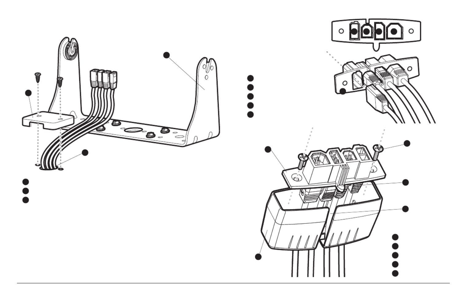
9. Insert cable connectors into the proper recesses on the cable
collector insert. The cable connectors are keyed to prevent reverse
installation, so be careful not to force the connectors into the wrong
slots. If you don’t have a cable for every hole in the insert, install the
blank plugs to protect the control head from the weather.
1
2
Cables Routed Behind Mounting Bracket
3
Gimbal Bracket
1
Grommet
2
Hole Cover
3
Cable Collector Insert
1
Screws
2
Cable Collector Cover
3
Tab on Insert
4
Slot on Cover
5
1
2
3
4
5
Power
1
Temp/Speed
2
Communications/GPS
3
Transducer
4
Cable Collector Insert
5
1 2 3 4
5

11 Installation - Power
10. While holding cables in place
in the cable collector insert,
thread the cables through
the slot in the bottom of the
cable collector cover, line up
the cable collector insert and
cover, then slide the cover
into place on the insert.
NOTE: The tab on the Cable Collector
insert goes into the slot on the cover.
11. Attach the cable collector insert to the cable collector cover using
the 2 Phillips screws provided.
12. Place the control head back onto the mounting bracket. Plug in the
cable collector assembly to the back of the control head. Cable
connectors and cable sockets are keyed to prevent reverse
installation, so be careful not to force the connectors into the wrong
sockets. Once the cable collector and all cables are plugged into the
back of the control head, lock the assembly into place by threading
the knurled screw into the threaded insert on the back of the
housing. Adjust the control head to the desired viewing angle and
secure by tightening the gimbal knobs.
NOTE: You may wish to dress the cabling with nylon wire ties in order to hold the
cables together and create a cleaner assembly.
The Humminbird® control head is now ready for operation.
Connecting the Control Head Power Cable to the Boat
A 6' (2 m) long power cable is included to supply power to the control head
You may shorten or lengthen the cable using 18 gauge multi-stranded
copper wire.
CAUTION: Some boats have 24 or 36 Volt electric systems, but the control head
MUST be connected to a 12 VDC power supply.
The control head power cable can be connected to the electrical system of
the boat at one of two places: a fuse panel usually located near the console,
or directly to the battery.
NOTE: Make sure that the power cable is disconnected from the control head at
the beginning of this procedure.
NOTE: Humminbird® is not responsible for over-voltage or over-current failur
The control head must have adequate protection through the proper selection
and installation of a 3 amp fuse.
Plug Cable Connector Assembly to
Back of Control Head
GROUND
GR
GR
GR
GR
O
O
O
O
UND
UND
UND
UND
POSITIVE
POS
POS
POS
POS
IT
IT
IT
IT IVE
IVE
IVE
IVE

12
Installation - Power
NOTE: In order to minimize the potential for interference with other marine
electronics, a separate power source (such as a second battery) may be
necessary.
You are now ready to install the transducer. Find the section that refers to
your specific transducer installation method.
Transducer Installation Overview
Proceed to the installation section that matches your transducer type. You
choices are as follows:
• DualBeam PLUS™ (XNT 9 20 T), Transom Mount858c, 958c:
• DualBeam PLUS™ (XNT 9 20 T), Inside the Hull Mount858c, 958c:
• Side Imaging® (XHS 9 HDSI 180T), Transom Moun898c SI, 998c SI:
• Trolling Motor Transducer InstallationAll units:
NOTE: Due to the wide variety of hulls, only general instructions are presented
in this installation guide. Each boat hull represents a unique set of requirements
that should be evaluated prior to installation. It is important to read the
instructions completely and understand the mounting guidelines before
beginning installation.
1a. If a fuse terminal is available, use crimp-on type electrical
connectors (not included) that match the terminal on the fuse
panel. Attach the black wire to ground (-), and the red wire to
positive (+) 12 VDC power. Install a 3 amp fuse (not included) for
protection of the unit. Humminbird® is not responsible for over-
voltage of over-current failures.
or...
1b. If you need to wire the control head directly to a battery, obtain
and install an inline fuse holder and a 3 amp fuse (not included)
for the protection of the unit. Humminbird® is not responsible for
overvoltage or over-current failures.
NOTE:
If the included transducer will not work for your application, you may
exchange it, NEW and UNASSEMBLED, with mounting hardware included, fo
a transducer appropriate for your application - often at very little or no charge
depending on the transducer. Call the Humminbird® Customer Resource
Center at for details and pricing, or visit1-800-633-1468 humminbird.com.

13 Transom Mount - DualBeam PLUS™
858c & 958c Transom Mount Transducer Installation
DualBeam PLUS™ Transducer, XNT 9 20 T (858c and 958c only)
The DualBeam PLUS™ transducer uses a Two Piece Kick-up transducer
mounting bracket.
NOTE: Due to the wide variety of hulls, only general instructions are presented in
this installation guide. Each boat hull represents a unique set of requirements that
should be evaluated prior to installation. It is important to read the instructions
completely and understand the mounting guidelines before beginning
installation.
NOTE: Your transducer may not look exactly like the transducer shown in the
illustrations, but it will mount in exactly the same way.
Overview
If you will be installing a DualBeam PLUS™ transom mounted transducer, u
the procedures in this section. There are several procedures you will have to
perform in order to install a transom-mounted transducer. They are as
follows:
• Locate the transducer mounting location
• Prepare the mounting location
• Assemble the transducer and perform initial mounting
• Route the transducer cable
• Connect the transducer cable
• Perform a final test of the transom transducer installation.
In addition to the hardware supplied with your transducer, you will need a
powered hand drill and various drill bits, various hand tools, including a rul
or straightedge, a level, a 12" plumb line (weighted string or monofilamen
line), marker or pencil, safety glasses and dust mask, and marine-grade
silicone sealant.
NOTE: When drilling holes in fiberglass hulls, it is best to start with a smaller bi
and use progressively larger drill bits to reduce the chance of chipping or flaking
the outer coating.

14
Transom Mount - DualBeam PLUS™
1. Locating the transducer mounting location
NOTE: If transom mounting is not possible because of a stepped hull or
cavitation noise, and you have a single layer fiberglass hull, In-hull installation is
an option. See Inside the Hull Transducer Installation for more information.
Turbulence: You must first determine the best location on the transom to
install the transducer. It is very important to locate the transducer in an area
that is relatively free of turbulent water. Consider the following to find the
best location with the least amount of turbulence:
• As the boat moves through the water, turbulence is generated by the
weight of the boat and the thrust of the propeller(s) - either clockwise
or counter-clockwise. This turbulent water is normally confined to areas
immediately aft of ribs, strakes or rows of rivets on the bottom of the
boat, and in the immediate area of the propeller(s). Clockwise
propellers create more turbulence on the port side. On outboard or
inboard/outboard boats, it is best to locate the transducer at least 15"
to the side of the propeller(s).
• The best way to locate turbulence-free water is to view the transom
while the boat is moving. This method is recommended if maximum
high-speed operation is a high priority. If this is not possible, select a
location on the transom where the hull forward of this location is
smooth, flat and free of protrusions or ribs.
• On boats with stepped hulls, it may be possible to mount the
transducer on the step. Do not mount the transducer on the transom
behind a step to avoid popping the transducer out of the water at
higher speeds; the transducer must remain in the water for the
control head to maintain the sonar signal.
Deadrise Angle
15”
Find a turbulence-free location at least 15" from the propeller(s)
and not in line with trailer bunks or rollers.
Level
Areas of Possible Turbulence
Rivets Strakes
Transom Hull
Stepped Hull
Step Rib

15 Transom Mount - DualBeam PLUS™
• If the transom is behind the propeller(s), it may be impossible to find
an area clear from turbulence, and a different mounting technique or
transducer type should be considered, such as an Inside the Hull
Transducer (see Inside the Hull Transducer Installation).
• If you plan to trailer your boat, do not mount the transducer too close
to trailer bunks or rollers to avoid moving or damaging the transducer
during loading and unloading of the boat.
• If high speed operation is critical, you may want to consider using an
In-Hull transducer instead of this Transom Mount transducer.
NOTE: The hydrodynamic shape of your transducer allows it to point straight down
without deadrise adjustment.
NOTE: If you cannot find a transom mount location that will work for your high-
speed application, find an In-Hull Transducer by contacting our Customer Resource
Center at either 1-800-633-1468 or by visiting our web site at humminbird.com.
2. Preparing the Mounting Location
In this procedure, you will determine the mounting location and drill two
mounting holes, using the transducer mounting bracket as a guide.
1. Make sure that the boat is level on the trailer, both from port to
starboard and from bow to stern, by placing your level on the deck of
the boat, first in one direction, then in the other.
2. Hold the mounting bracket against the transom of the boat in the
location you have selected. Align the bracket horizontally, using the
level; make sure that the lower corner of the bracket does not
protrude past the bottom of the hull, and there is at least 1/4"
clearance between the bottom of the bracket and the bottom of the
transom for fiberglass boats, and 1/8" clearance for aluminum
boats.
NOTE: If you have a flat-bottomed aluminum boat, some additional adjustment
may be needed to accommodate the rivets on the bottom of the boat (i.e. the gap
may need to be a little smaller than 1/8"). This will help you to avoid excessive
turbulence at high speeds.
NOTE: If your propeller moves clockwise (in forward, as you're facing the stern o
the boat from behind), mount the transducer on the starboard side, and align the
bottom right corner of the mounting bracket with the bottom of the boat. If your
propeller moves counter-clockwise (in forward, as you're facing the stern of the
boat from behind), mount the transducer on the port side, and align the bottom
left corner of the mounting bracket with the bottom of the boat.
Positioning the
Mounting Bracket
Level
Level
Boat Hull Types Require
Different Mounting Positions
1/4” for fiberglass
1/8” for aluminum

16
Transom Mount - DualBeam PLUS™
3. Continue to hold the bracket on the transom of the boat, and use a
pencil or marker to mark where to drill the two mounting holes.
Mark the drill holes near the top of each slot, making sure that your
mark is centered in the slot.
4. Make sure that the drill bit is perpendicular to the actual surface of
the transom, NOT parallel to the ground, before you drill. Using a
5/32” bit, drill the two holes only to a depth of approximately 1”.
NOTE: On fiberglass hulls, it is best to use progressively larger drill bits to reduce
the chance of chipping or flaking the outer coating.
3. Assembling the Transducer and Initial Mounting
In this procedure, you will assemble the transducer using the hardware
provided, then mount it and make adjustments to its position without lockin
it in place.
NOTE: You will initially assemble the transducer and the pivot arm by matchin
the two ratchets to a numbered position on the transducer knuckle. Further
adjustments may be necessary.
1a. If you already know your transom angle, refer to the chart below for
the initial position to use to set the ratchets. If your transom is
angled at 14 degrees (a common transom angle for many boats) use
position 1 for the ratchets. In either case, go to step 2.
or...
1b. If you do not know your transom angle, measure it using a plumb
line (weighted nylon string or monofilament line) exactly 12 inches
long. Hold the top of the plumb line against the top of the transom
with your finger, and wait until the line hangs straight down. Using
a ruler, measure the distance from the bottom of the plumb line to
the back of the transom, then use the chart.
-2 -1 0 1 2 3 4 5 6 7 8 9 10 11 12 13 14 15 16 17 18 19 20 21 22 23 24
Transom le Ang (°)
Bead Alignment
Number 1 4 2 5 3 1 4 2 5
25 26 27
3
28 29 30
1
Measured Distance (x)
1.1cm
1/2“
0.0 cm
0“
2.5 cm
1“
4.3 cm
1 5/8“
5.9 cm
2 3/8“
7.6 cm
3“
9.3cm
3 5/8“
11.1cm
4 3/8“
12.9cm
5“
14.9cm
5 7/8“
16.9cm
6 5/8“
Using the Mounting Bracket to Mark the Initial Drill Holes
Mark Initial Drill Holes
Fourth Hole
Third Hole
NOTE: The third hole should not be drilled until the angle and height of the
transducer is finalized, which you will not do until a later procedure.

17 Transom Mount - DualBeam PLUS™
NOTE: It is important to take your measurement in
the figure showing Measuring the Transom
Angle, from exactly 12 inches down from the top
of the transom.
2. Place the two ratchets, one on either
side of the transducer knuckle, so that
the beads on each ratchet line up with
the desired position number on the
knuckle. If you are setting the ratchets
at position 1, the beads on each ratchet
will line up with the rib on the
transducer knuckle to form one
continuous line on the assembly.
NOTE: The ratchets are keyed; make sure that
the square teeth on each ratchet face the
square teeth on the transducer knuckle, and
the triangular teeth face outward.
Hold the ratchets on the transducer knuckle with one hand and fit
the pivot arm over them until it snaps into place with the other
hand. Refer to the illustration.
Transom
Angle in
degrees
(°)
Measured
Distance (X)
Measuring the Transom Angle
Plumb
line
Weight
Transducer Knuckle Positions Ratchets Placed in Position 1
Ratchets Placed in Position 2 Fitting the Pivot Arm Over the Ratchet
Knuckle
Bead
Ratchet
Rib
Rib at
position 1
Beads
Ratchet

19 Transom Mount - DualBeam PLUS™
7. Adjust the transducer assembly vertically, until the seam on the
leading edge of the transducer (the edge closest to the transom of
the boat) is level and just slightly below the hull.
NOTE: The transducer has a natural downward slant of 4-5 degrees from leading
edge (closest to the boat transom) to trailing edge (farthest away from the boat).
Looking at the back of the transducer, the seam should be slightly below the
bottom of the hull.
8. Continue to adjust until the bracket is also level from port to
starboard (horizontally level as you look at the transducer from
behind the boat).
9. Mark the correct position on the transom by tracing the silhouette
of the transducer mounting bracket with a pencil or marker.
10. Tighten the pivot bolt, using the pivot screw and nut to lock the
assembly. Hand tighten only!
11. Snap open the assembly and hand-tighten the two mounting
screws, then snap the assembly closed.
Adjusting the Initial Transducer Angle
Leading edge
One click too high
Correctly aligned
(transducer side
seam aligned with
boat bottom)
Trailing edge
One click too low
NOTE:
You will drill the third mounting hole and finalize the installation after
you route the cable and test and finish the installation in the following
procedures.
Adjusting the Transducer
Mounting Position
Seam aligned with boat hull
Leveling the Mounting
Assembly Horizontally
Level
Level

20
Transom Mount - DualBeam PLUS™
4. Routing the Cable
The transducer cable has a low profile connector, which must be routed to
the point where the control head is mounted. There are several ways to route
the transducer cable to the area where the control head is installed. The
most common procedure routes the cable through the transom into the boat.
NOTE: Your boat may have a pre-existing wiring channel or conduit that you can
use for the transducer cable.
1. Unplug the other end of the transducer cable from the control head.
Make sure that the cable is long enough to accommodate the
planned route by running the cable over the transom.
CAUTION! Do not cut or shorten the transducer cable, and try not to damage the
cable insulation. Route the cable as far as possible from any VHF radio antenna
cables or tachometer cables to reduce the possibility of interference. If the cable
is too short, extension cables are available to extend the transducer cable up to
a total of 50'. For assistance, contact the Customer Resource Center at
humminbird.com 1-800-633-1468or call for more information.
NOTE: The transducer can pivot up to 90 degrees in the bracket. Allow enough
slack in the cable for this movement. It is best to route the cable to the side of
the transducer so the transducer will not damage the cable during movement.
2a. If you are routing the cable over the transom of the boat, secure the
cable by attaching the cable clamp to the transom, drilling 9/64"
diameter holes for #8 x 5/8" wood screws, then skip directly to
procedure 5, Connecting the Cable.
or...
2b. If you will be routing the cable
through a hole in the transom, drill a
5/8" diameter hole above the
waterline. Route the cable through
this hole, then fill the hole with
marine-grade silicone sealant and
proceed to the next step
immediately.
3. Place the escutcheon plate over the
cable hole and use it as a guide to
mark the two escutcheon plate
mounting holes. Remove the plate,
drill two 9/64" diameter x 5/8" deep
holes, and then fill both holes with
marine-grade silicone sealant. Place
the escutcheon plate over the cable
hole and attach with two #8 x 5/8"
wood screws.
4. Route and secure the cable by attaching the cable clamp to the
transom; drill one 9/64" diameter x 5/8" deep hole, then fill the hole
with marine-grade silicone sealant, then attach the cable clamp
using a #8 x 5/8" screw.
5. Plug the other end of the transducer cable back into the control
head connection holder.
Routing the Cable

21 Transom Mount - DualBeam PLUS™
NOTE: If there is excess cable that needs to
be gathered at one location (as shown in
the illustration), dress the cable routed from
both directions so that a single loop is left
extending from the storage location.
Doubling the cable up from this point, form
the cable into a coil. Storing excess cable
using this method can reduce electronic
interference.
5. Connecting the Cable
Insert the transducer cable into the appropriate terminal slot. The cable
connectors are labeled, and there are corresponding labels on the cable
holder on the rear of the control head. The slots are keyed to prevent
reversed installation, so be careful not to force the connector into the holder.
Refer to your manual and/or control head installation guide for the correct
procedure for installing the cable connectors to the control head.
1. Plug the other end of the transducer cable back into the control
head connection holder.
Your control head is now ready for operation.
6. Test and Finish the Installation
Once you have installed both the control head and the transom transducer,
and have routed all the cables, you must perform a final test before locking
the transducer in place. Testing should be performed with the boat in the
water, although you can initially confirm basic operation with the boat out
of the water.
1. Press POWER once to turn the control head on. If the unit does not
power up, make sure that the connector holder is fully seated in the
receptacle and that power is available.
2. If all connections are correct and power is available, the
Humminbird® control head will enter Normal operation.
3. If the bottom is visible on-screen with a digital depth readout, the
unit is working properly. Make sure that the boat is in water greater
than 2' but less than the depth capability of the unit, and that the
transducer is fully submerged, since the sonar signal cannot pass
through air.
NOTE: The transducer must be submerged in water for reliable transducer
detection.
4. If the unit is working properly, gradually increase the boat speed to
test high-speed performance. If the unit functions well at low
speeds, but begins to skip or miss the bottom at higher speeds, the
transducer requires adjustment.
5. If you have the correct angle set on the transducer, yet lose a bottom
reading at high speed, adjust the height and the running angle in
small increments to give you the ideal transducer position for your
boat. First, adjust the height in small increment.
Storing Excess Cable

22
Transom Mount - DualBeam PLUS™
NOTE: The deeper the transducer is in the water, the more likely that a rooster
tail of spray will be generated at high speeds, so make sure that the transducer
is as high as it can be and still be submerged in the water.
If you are still not getting good high speed readings, you may need
to disassemble the transducer mounting assembly and re-position
the ratchets.
If you do change the transducer position, re-trace the position of the
mounting bracket before proceeding.
NOTE: It is often necessary to make several incremental transducer adjustments
before optimum high speed performance is achieved. Due to the wide variety of
boat hulls, however, it is not always possible to obtain high speed depth
readings.
6. Once you have reached a consistently good sonar signal at the
desired speeds, you are ready to lock down the transducer settings.
Force the pivot to the Up position to gain access to the mounting
screws, then re-align the mounting bracket against the transom of
the boat to match the traced silhouette. Check the bracket position
with the level again to make sure it is still level, then mark the third
mounting hole using a pencil or marker. Unscrew and remove the
mounting screws and the transducer assembly and set aside.
7. Drill the third mounting hole, using a 5/32” drill bit. Use a marine-
grade silicone sealant to fill all three drilled mounting holes,
especially if the holes penetrated the transom wall.
NOTE: On fiberglass hulls, it is best to use progressively larger drill bits to reduce
the chance of chipping or flaking the outer coating.
8. Re-position the transducer assembly
against the transom of the boat, then
hand-install all three screws. Make
sure that the transducer location and
the pivot angle have not changed,
then fully tighten all three mounting
screws. Snap the pivot back down. If
you have performed the preceding
procedures correctly, the transducer
should be level and at the right
height for optimal operation.
Fully Tighten All Three
Mounting Screws

23 Transom Mount - DualBeam PLUS™
Locking Down the Transducer (Optional)
NOTE: You have the option to lock down the Two Piece Kick Up bracket if you do
not want the transducer to kick up. Please be aware, however, that the
transducer can be damaged if it is locked down and it strikes debris in the water.
1. To lock down the transducer, trace
the position of the mounting
bracket. Force the pivot to the Up
position to gain access to the
mounting screws, then re-align the
mounting bracket against the
transom of the boat to match the
traced silhouette. Check the bracket
position with the level again to make
sure it is still level, then mark the
fourth mounting hole using a pencil
or marker. Unscrew and remove the
mounting screws and the transducer
assembly and set aside.
2. Drill the fourth mounting hole, using a 9/64" drill bit. Use a marine
grade silicone sealant to fill all four drilled mounting holes,
especially if the holes penetrate the transom wall.
3. Re-position the transducer assembly
against the transom of the boat, then
hand install the first three screws
(two on the outside edges and one in
the 3rd mounting hole). Make sure
that the transducer location and the
pivot angle have not changed, then
fully tighten all three mounting
screws. Hand tighten only!
4. Snap the pivot back down. Install
#8 x 1" wood screw into the 4th hole
to lock down the pivot arm. Hand-
tighten only!
Fully Tighten All Three
Mounting Screws
Marking the Fourth Drill Hole
for Optional Lock Down
Mark Initial Drill Holes
Fourth Hole
Third Hole

24
858c & 958c Inside the Hull Transducer Installation
DualBeam PLUS™ Transducer, XNT 9 20 T (858c and 958c only)
NOTE: Do NOT install the Side Imaging transducer inside the hull, as the side®
looking beams cannot penetrate the hull. Only the DualBeam PLUS™ transducer
can be mounted inside the hull.
If you choose to mount your transducer of your boat, performinside the hull
the procedures in this section. In-hull mounting generally produces good
results in single thickness fiberglass-hulled boats. Humminbird® cannot
guarantee depth performance when transmitting and receiving through the
hull of the boat, since some signal loss occurs. The amount of loss depends
on hull construction and thickness, as well as the installation position and
process.
NOTE: In-hull mounting requires an installed and operational control head.
NOTE: The integral temperature probe will not work with in-hull mounting, so
you may either want to consider purchasing a Temperature/Speed accessory, a
Temp. Sensor, or obtaining a different transducer. Humminbird® offers a
transducer exchange program to swap the NEW and UNASSEMBLED transducer,
accompanied by mounting hardware, for one without an integral temperature
probe. Call the Humminbird® Customer Resource Center at 1-800-633-1468 for
details, or visit humminbird.com for more information.
NOTE: Your transducer may not look exactly like the transducer shown in the
illustrations, but it will mount in exactly the same way.
There are several procedures you will have to perform in order to install a
transducer inside the hull. They are as follows:
• Locate transducer mounting location
• Perform a trial installation
• Route the transducer cable
• Permanently mount the transducer
1. Locating the transducer mounting location
Decide where to install the transducer on the inside of the hull. Consider the
following to find the best location:
• Observe the outside of the boat hull to find the areas that are mostly
free from turbulent water. Avoid ribs, strakes and other protrusions,
as these create turbulence.
• As a general rule, the faster the boat can travel, the further aft and
closer to the centerline of the hull the transducer has to be located
in order to remain in contact with the water at high speeds.
This installation requires slow-cure two-part epoxy. Do not use silicone
or any other soft adhesive to install the transducer, as this material
reduces the sensitivity of the unit. Do not use five-minute epoxy, as it has
a tendency to cure before all the air bubbles can be purged, thus
reducing signal strength.
Inside the Hull Mount - DualBeam PLUS™

25 Inside the Hull Mount - DualBeam PLUS™
2. Trial installation
You will not be able to adjust the mounting after an inside the hull
transducer is installed. It is best, therefore, to perform a trial installation first
that includes running the boat at various speeds, in order to determine the
best mounting area before permanently mounting the transducer.
1. Plug the transducer into the control head, then power up the control
head. When the control head detects a functioning transducer, it
will automatically enter Normal operating mode.
2. View the sonar signal at its best by holding the transducer over the
side, immersed in the water, so that it is pointing straight down over
a known flat bottom. Use the display to benchmark against the
sonar signal that will be detected once the transducer is placed in
the hull.
3. Place the transducer body face down at the identified mounting
location inside the hull, with the end that has the mounting knuckle
pointed towards the bow of the boat.
4. Fill the hull with enough water to submerge the transducer body.
Use a sand-filled bag or other heavy object to hold the transducer in
position. The transducer cannot transmit through air, and the water
purges any air from between the transducer and the hull, and fills
any voids in the coarse fiberglass surface.
5. View the sonar signal on the display and compare against what you
observed in Step 2, making sure that the boat is in the same location
as it was during your observations in Step 2. If the results are
comparable, move on to Step 6. Otherwise, locate a new position in
the hull and repeat Steps 3 through 5.
Preferred Mounting Area
Areas of Possible Turbulence
Rivets Strakes
Transom Hull
Stepped Hull
Step Rib

26
Inside the Hull Mount - DualBeam PLUS™
6. Run the boat at various speeds and water depths while observing
the screen on the control head. If depth performance is required,
test the transducer in water at the desired depth. If the performance
is acceptable, move on to Step 7. If the performance is not
acceptable, repeat Steps 3 through 6.
7. Once you have determined the best mounting location using the
above steps, mark the position of the transducer.
3. Routing the cable
1. Once the mounting location is determined and you have marked the
position of the transducer, route the cable from the transducer to
the control head.
4. Permanently mounting the transducer
1. Make sure the position of the transducer is marked.
2. You may have to disconnect the cable to the control head and
reconnect it at the end of this procedure.
3. Remove the water from inside the hull and thoroughly dry the
mounting surface. If the surface is excessively rough, it may be
necessary to sand the area to create a smooth mounting surface.
4. Slowly and thoroughly mix an ample quantity of two-part slow cure
epoxy. Avoid trapping air bubbles.
5. Coat the face of the transducer and the inside of the hull with epoxy.
6. Press the transducer into place with a slight twisting motion to
purge any trapped air from underneath, keeping the end of the
transducer that has the mounting knuckle pointed forward, towards
the bow of the boat.
NOTE: Proper operation requires the end of the transducer that has the mounting
knuckle to face towards the bow of the boat.
7. Weight the transducer so that it will not move while the epoxy is
curing.
NOTE: When the epoxy cures, no water is necessary inside the hull.
8. If you unplugged the transducer cable at the beginning of this
procedure, plug it back into the control head.
NOTE: Neither water, spilled gasoline, nor oil will affect the performance of the
transducer.

29 Transom Mount - Side Imaging®
• The hydrodynamic shape of your transducer allows it to point straight
down without deadrise adjustment.
• On boats with stepped hulls, it may be possible to mount the trans-
ducer on the step. Do not mount the transducer on the transom
behind a step to avoid popping the transducer out of the water at
higher speeds; the transducer must remain in the water for the
control head to maintain the sonar signal.
• If the transom is behind the propeller(s), it may be impossible to find
an area clear from turbulence, and a different mounting technique or
transducer type should be considered (see Trolling Motor
Transducer Installation).
• The Side Imaging® transducer must NOT have anything obstructing
the ‘view’ of the side looking beams, i.e. nothing can be in the line
of sight of these beams (not a hull, motor, or other transducer, etc).
Mounting the transducer bracket to the boat
1. Remove the transducer mounting template from this manual. See
Appendix A for the Transducer Mounting Template.
2. Hold the template on the transom of the boat in the location where
the transducer will be installed. Align the template vertically,
matching the lower edge of the transom with the bottom corner of
the template. If your propeller moves clockwise as the boat moves
forward, mount the transducer on the starboard side, and use the
bottom left corner of the template. If your propeller moves counter-
clockwise as the boat moves forward, mount the transducer on the
port side, and use the bottom right corner of the template.
3. Using a pencil or punch, mark the three mounting holes on the
transom. Do not mark or drill any other holes at this time.
4. Using a 5/32" (4.0 mm) bit, drill the three holes to a depth of
approximately 1" (25 mm). On fiberglass hulls, it is best to use
progressively larger drill bits to reduce the chance of chipping or
flaking the outer coating. Use a marine-grade silicone sealant to fill
the drilled holes.
Attaching the Bracket
15” (380 mm) from prop(s)

30
Transom Mount - Side Imaging®
5. Align the metal mounting bracket with the mounting holes. The center
slot should be above the two outer slots. (This bracket and all other
hardware supplied is top quality stainless steel for maximum strength
and corrosion protection.) Insert the three #10 - 1" long screws into the
drilled holes, but do not completely tighten.
Attaching the pivot to the transducer
1. Attach the pivot to the transducer body, using the two 1/4"-20 x 5/8"
(16 mm) machine screws, toothed washers, and square nuts. The
toothed washers must fit on the inside of the transducer ears,
between the pivot and the ears. The square nuts will be prevented
from rotating by the pocket in the back of the pivot. An Allen wrench
is provided which fits all the 1/4"-20 screws, but do not fully tighten
the screws at this time.
Mounting the transducer pivot assembly to the bracket
1. Slide the assembled transducer into the metal bracket from the
bottom, aligning the large hole at the top of the bracket with the
hole in the pivot.
2. Insert the headed pin through the pivot holes in the bracket and
pivot. The headed pin can be inserted from either side of the
bracket.
3. Place the nylon washer over the opposite end of the headed pin.
Place the stainless washer over the 1/4"-20 x 5/8" (16 mm) screw
threads, then insert into the opposite end of the headed pin and
finger tighten only. The screw has a thread locking compound on the
threads to prevent loosening, and should not be fully tightened until
all adjustments are made.
NOTE: The running position of the transducer is now completely adjustable.
Subsequent adjustment may be necessary to tweak the installation after high
speed testing.
Attach the Pivot
2
3
4
1
Insert the square nuts
1
Toothed Washer
2
Pivot
3
Machine Screw
4
Screw
1
Headed Pin
2
Allen Wrench
3
Nylon Washer
4
Stainless Washer
5
3
15
4
2

31 Transom Mount - Side Imaging®
Adjusting the running position of the transducer
The transducer mounting bracket allows height and tilt adjustment, while
the pivot bolt allows angular adjustment. These adjustments will help
reduce cavitation. Initially, adjust the transducer as described in the
following paragraphs. Further adjustment may be necessary to refine the
installation after high-speed testing.
1. First, adjust the pivot angle of the transducer body, so it is parallel
with the length of the hull of the boat.
2. Fully tighten the two pivot screws, using the supplied Allen wrench.
Access to the pivot screws is provided by the lower holes in the side
of the mounting bracket. It may be necessary to re-tighten the pivot
bolt after initial use as the plastic may still be conforming to the
pressure from the lock washers.
3. Adjust the height of the assembly so the face
of the transducer is 1/8" (3 mm) to 1/4" (6 mm)
beneath the bottom of the transom, and fully
tighten the three mounting screws.
4. In order to gain access to the mounting
screws, the transducer assembly must be
pivoted up in the bracket as shown. Be careful
not to alter the running angle as some force is
necessary to pivot the assembly.
5. If access to the top mounting hole is not possible due to the selected
height of the transducer, fully tighten the two lower screws, then
simply remove the headed pivot pin and the transducer assembly,
and tighten the top screw, then reassemble.
6. Confirm that the pivot angle has not changed and that all mounting
screws are fully tightened.
Tighten the Mounting
Screws
Normal Cavitation Cavitation that will cause
erratic sonar readings

33 Test & Finish Transducer Installation
Trolling Motor Transducer Installation
Several styles of the transducer are compatible with trolling motor mounting.
If you have a trolling motor bracket, refer to the separate installation
instructions that are included with the bracket.
NOTE: After trolling motor transducer installation, please perform the final
testing and then finalize the installation (see Test and Finish the Transducer
Installation).
Trolling Motor Transducer Options
If you don’t have a trolling motor transducer,
there are several options:
• You may purchase a Trolling Motor Adapter kit
that will allow you to mount the transducer on the
trolling motor.
• You may also exchange your NEW and UNASSEMBLED transducer
(with mounting hardware included) for a trolling motor transducer.
There are also several transducer switches available that support the
following configurations:
• Two control heads with one transducer
• Two transducers with one control head.
NOTE: 1-800-633-1468Call the Humminbird® Customer Resource Center for
details and pricing, or visit humminbird.com for more information.
Test and Finish the Transducer Installation
When you have installed both the control head, the transducer, and
accessories, and have routed all the cables, you must perform a final test
before locking the transducer in place. Testing should be performed with the
boat in the water, although you can initially confirm basic operation with the
boat out of the water.
1. Press the POWER/LIGHT key once to turn the control head on. There
will be an audible chirp when the key is pressed correctly. If the unit
does not power-up, make sure that the connector holder is fully
seated and that power is available.
2. If all connections are correct and power is available, the control
head will enter Normal operation. If no transducer is detected (or
one is not connected), the unit will go into Simulator mode and will
indicate this by displaying the word Simulator on the control head
display.
NOTE: The transducer must be submerged in water for reliable transducer
detection.
3. If the bottom is visible on-screen with a digital depth readout, the
unit is working properly. Make sure that the boat is in water greater
than 2 ft (.6 m) but less than the depth capability of the unit, and
that the transducer is fully submerged, since the sonar signal
cannot pass through air.

35 GPS- Stem Mount
Stem Mounting with an Existing 1" - 14 Thread Stem
Follow these steps to stem mount the GPS receiver:
NOTE: If you have an existing stem for mounting the GPS receiver, proceed
directly to step 2 of the following procedure.
1. Determine the best location to mount your GPS receiver. Preplan
and test the cable routing to your control head before any drilling or
cutting of your boat surfaces. If you have purchased hardware to
stem mount your GPS receiver, follow the instructions included with
that hardware to mount the stem (antenna pole).
NOTE: AS-EC10 10' extension cables are available from Humminbird® if your
planned routing exceeds 20', (6 m). Maximum cable length, including extensions,
should not exceed 50' (16 m).
NOTE: Remember to caulk or seal screw holes and drilled holes as needed to
protect your boat from water damage.
2. Screw on the receiver base to the stem
first, making sure that the stem pipe
does not protrude from the receiver
base. This adds protection to the cable
when pulling it through the pipe stem.
In addition to this, de-burr the pipe
edges to reduce cable abrasion.
3. Use electrical tape to secure the NMEA pigtail to the cable as
shown.
NOTE: Leave the NMEA pigtail secured to the cable unless needed. This will
make removing the receiver easier.
4. Route the GPS receiver cable through the stem and continue with
the planned route you chose in step 1.
5. Attach the GPS receiver to its base using the included #6 - 7/8"
screws.
NMEA Pigtail Taped
1
NMEA Pigtail Cable Out
2
Mounting Screws
3
Cable Route
4
1
2
4
3
Receiver
1
Receiver Base
2
Stem Pipe
3
1
2
3

Access Under Mounting Location
Follow these steps to deck mount the GPS receiver when routing the cable
down through the mounting location:
1. Determine the best location, then test route the 20' (6 m) cable from
the mounting location to the control head.
NOTE: Installation details may vary with unit configuration.
2. Mark the mounting location and drill a 3/4" (19 mm) hole for the
cable and cable plug. Route the cable.
3. Cover the cable hole with the receiver. Make sure the receiver is
flush on the surface and mark the two mounting holes with a pencil
or punch.
4. Move the receiver to the side and drill two pilot holes using a 9/64"
(3.5 mm) bit.
NOTE: Remember to caulk or seal screw holes and drilled holes as needed to
protect your boat from water damage.
5. Align the GPS receiver screw holes over the pilot screw holes and
attach with the #8 - 1 1/4" Phillips head screws. Hand tighten only!
NOTE: If the mounting surface is thin and made of a lighter material, a backing
material may be needed below the mounting surface.
No Access Under Mounting Location
Follow these steps to deck mount the GPS receiver in a situation where you
must route the cable to the side because there is no space for a cable
underneath the mounting location.
1. Determine the best location, then test route the cable from the
mounting location to the control head.
NOTE: AS-EC10 10' extension cables are available from Humminbird® if your
planned routing exceeds 20', (6 m). Maximum cable length, including extensions,
should not exceed 50' (16 m).
2. Confirm the cable length is good and route the cable from the
receiver to the control head. If holes are required to route the cable,
they must be 3/4" (19 mm) to allow for the cable connector. Secure
the NMEA pigtail with electrical tape.
NOTE: Remember to caulk or seal screw holes and drilled holes as needed to
protect your boat from water damage.
Access Under Mounting Location No Access Under Mounting Location
36
GPS- Access Under/No Access Under Mount

3. The GPS receiver has two wire routing notches. Use the cable notch
closest to the intended cable route.
4. With the cable routed, position the GPS receiver in the planned
mounting location and mark the mounting holes with a pencil or
punch.
5. Move the GPS receiver to the side and drill the two 9/64" (3.5 mm)
pilot holes.
6. Align the GPS receiver's screw holes over the pilot screw holes and
attach with the #8 - 1 1/4" Phillips head screws. Hand tighten only!
Finish Routing the Cable and
Check GPS Receiver Operation
After installing a GPS receiver, you should perform the following procedure
to finish routing the GPS cable to the control head and to check to make sure
that the control head is working correctly.
1. Secure the cable along its path to the control head as needed with
cable ties.
2. Plug the GPS receiver cable into the Communications port on the
control head. See Testing the System Installation to use the
System Status start-up option and/or the GPS Diagnostic View to
confirm a good installation.
Power
1
Temp/Speed
2
Communications/GPS
3
Transducer
4
Cable Collector Insert
5
1 2 3 4
5
37 GPS- Route Cable & Test Operation

38
Test System Installation
Testing the System Installation
After you have completed the installation of the control head, transducer,
and any other accessories such as the GPS receiver, and have made all the
cabling connections required, you must test the installation before using the
system. Thorough testing should be performed with the boat in the water;
however, you can confirm basic operation initially with the boat out of the
water as well.
To test the installation:
1. Press the POWER/LIGHT key on the control head once to turn on the
control head. (There will be an audible chirp to let you know that you
pressed the key, and the initial Title screen will appear.) If the unit
does not power up, make sure that power is available. While the
Title screen is shown on the display, press the MENU key to display
the Start-Up Options menu. Use the UP or DOWN 4-WAY Cursor
keys to position the cursor, then the RIGHT Cursor key to select
System Status from the Start-Up Options menu (see the Start-Up
Options Menu section for more information about these menu
choices). The System Status Self Test screen will appear.
NOTE: If you wait too long, the system will default to whichever menu mode
happens to be highlighted, and you will have to start again.
2. Self Test displays results from the internal diagnostic self test,
including unit serial number, Printed Circuit Board (PCB) serial
number, software revision, total hours of operation and the input
voltage. See System Status for more information about the Self Test.
3. From the System Status screen, view accessory connections by
pressing the VIEW key. See for more informationSystem Status
about the Accessory Test.
NOTE: The speed will be detected only if the paddlewheel has moved since the
Fishing System has been powered up.
4. From the System Status screen, see a GPS Diagnostic View by
pressing the View key. GPS Diagnostic View shows a sky chart and
numerical data from the GPS receiver. The sky chart shows the
location of each visible GPS satellite with its satellite number and a
signal strength bar. A dark grey bar indicates that the satellite is
being used to determine your current position. A light gray bar
indicates that the satellite is being monitored, but is not yet being
used. See for more information about the GPSSystem Status
Diagnostic View.

39 What’s on the Control Head
Power On the Control Head
Press the POWER/LIGHT key to power on your Humminbird® control
head. When the Title screen is displayed, press the MENU key to access the
Start-Up Options Menu. Select Normal (if there is a transducer attached to
the control head) or Simulator (if there isn’t a transducer attached to the
control head).
NOTE: If a functioning transducer is connected, Normal will be selected
automatically at power up, and your Fishing System can be used on the water.
Select Simulator to learn how to use your control head and save settings in
advance for later use. See Start-Up Options Menu for more information.
What’s on the Control Head
Your Fishing System user interface is easy to use. A combination of key
different views, and situation-specific, customizable menus allows you t
control what you see on the color display. Refer to the following illustratio
and see Key Functions Views, , and The Menu System for more information.
*Your control head will have one of the INFO keys shown here
Both keys function in the same way.
Screen 4-WAY Cursor Control Key
1 7
MMC/SD Card Slot MENU Key
2 8
ZOOM (+/-) Keys VIEW Key
39
POWER/LIGHT Key EXIT Key
4 10
INFO Key* VIEW PRESET Keys
5
MARK Key
6
11
1
3
5
6
7
8
9
10
11
2
4
GOTO Key
12
12
998c SI Combo Title Screen

40
Key Functions
Key Functions
Your Fishing System has a set of easy to use keys that give you flexibility and
control over your fishing experience.
POWER/LIGHT Key
The is used to power the Fishing SystemPOWER/LIGHT key
on and off. You can also use the POWER/LIGHT key to adjust
the backlight and contrast of the display.
Power On the control head: Press the POWER/LIGHT key to power on the
unit. When the Title screen is displayed, press the MENU key to access the
Start-Up Options Menu.
Power Off the control head: Press and hold the POWER/LIGHT key for 3
seconds. A message will appear to indicate how many seconds there are
until shutdown occurs. To ensure that shutdown occurs properly and any
menu settings will be saved, your Fishfinder should always be turned off
using the POWER/LIGHT key.
Adjust the Backlight or the Display
Background Color: Press the POWER/LIGHT
key to access the Light and Background
submenu. Use the 4-WAY Cursor Control key
to select Light or Background, and then use
the LEFT or RIGHT Cursor key to change the
settings. Press EXIT to exit the Light and
Background submenu.
NOTE: Your control head will start up with the backlight on and will automaticall
turn it off to conserve power.
VIEW Key
The is used to cycle through all available viewsVIEW key
Press the VIEW key to advance to the next view. Press the
VIEW key repeatedly to cycle through all available views
Views can be hidden to optimize the system to your fishing
requirements (see Views View Menu Tabor ).
MENU Key
The is used to access the menu system. SeeMENU key The
Menu System for more information.
Start-Up Options Menu: Press the MENU key during the power up
sequence to view the Start-Up Options menu.
X-Press™ Menu: Press the MENU key once in any view to access the X
Press™ Menu, which provides frequently-used menu settings that
correspond with the current view or navigation mode.
Main Menu: Press the MENU key twice in any view to access the Main
Menu, which is organized under tabbed headings to help you find a specifi
menu item quickly.

41 Key Functions
4-WAY Cursor Control Key
(RIGHT, LEFT, UP, or DOWN Cursor Keys)
The 4-WAY Cursor Control key has multiple functions,
which depend on the view, menu, or situation.
• Press the DOWN or UP Cursor keys to highlight aMenu Selection:
menu option, then press the RIGHT or LEFT Cursor keys to change a
menu setting. The changes will be activated and saved immediately.
• Freeze Frame: In Sonar View, press any arrow on the 4-WAY Cursor
Control key to freeze the display and move the active cursor to a
location on the screen. A cursor dialog box will display to show the
depth of the location you choose.
• Active Cursor: Press any arrow on the 4-WAY Cursor Control key, and
the active cursor will appear on the screen.
• Chart Views: The 4-WAY Cursor Control key also pans the charts and
highlights decluttered waypoint icons.
• The 4-WAY Cursor Control key controls the motionBird’s Eye View:
of the eye point.
• Snapshot and Recording View: Press the UP or DOWN Cursor keys
to highlight a recording icon, and then press the RIGHT Cursor key to
start recording playback. Press the RIGHT or LEFT Cursor keys to
control the speed of playback.
VIEW PRESET Keys
The are used to save your three favoritVIEW PRESET keys
views for quick retrieval. Instead of using the VIEW key t
cycle through all the views to find the one you want, you can
program the VIEW PRESET keys to display a specific vie
immediately. See for more information.Views
EXIT Key
The EXIT key has multiple functions, which depend on the
situation:
• press the EXIT key to cancel the alarm.If an alarm is sounding,
• press the EXIT key to exit the menu modeIf a menu tab is selected,
and return to the view.
• press the EXIT key to return to the previous levelIf a menu is active,
in the menu system.
• From any view, press the EXIT key to cycle through the available
views in reverse order.
• If Freeze Frame is active, press the EXIT key to return to a scrolling
display.
• press the EXIT key to remove the cursor fromIf the Cursor is active,
the display.
NOTE: In Freeze Frame or Active Cursor mode, you can also make the
cursor move diagonally by pressing in between two of the arrows on the
4-WAY Cursor Control key.

43 Multi-Media Card Slots
Multi-Media Card
(MMC)/SD Slots
The two multi-media card (MMC)/SD slots
on your control head can be used with
MMC/SD cards (optional-purchase required)
to add detailed charts to your Fishing
System, update your Fishing System
software, or export navigation data from
your Fishing System.
To insert an MMC/SD card:
1. Remove the MMC/SD slot cover.
2. Position the MMC/SD card so that the label faces the left side of the
unit, and insert the card into the slot. Press down on the card until
it clicks into place.
3. Close the slot cover and turn the knob just 1/4 of a turn to close. Do
NOT overtighten, as this will not improve water resistance and may
damage the cover.
4. To Remove:Press the MMC/SD card into the slot and then release.
The card will eject, and you can then pull the card from the slot.
Add Maps to Your Fishing System
Your Fishing System includes a built-in Contour XD™ or UniMap™ wi
more detailed map of North America (Domestic models) or a detailed map
Europe and Southeast Asia, including Australia and New Zealand
(International models).
You can also purchase MMC/SD cards with additional chart information f
a particular location.
• When you install the MMC/SD cards in your controlAuto Select:
head, your Fishing System will retrieve the chart and display it
automatically.
• You can also choose which chart to display with theChart Select:
Chart Select menu option in the Chart Menu Tab. Choose Right (card
slot) or Left (card slot) to select the MMC/SD card you’d like to use.
(see Chart Menu Tab: Chart Select).
• The Chart Menu Tab will change to display menuMenu Options:
options that correspond with the active chart (see Chart Menu Tab).
NOTE: The MMC/SD Cards require a separate purchase. Your Fishing
system supports LakeMaster® and Navionics® Cartography on MMC or SD
card media.NOTE: The MMC/SD Cards require a separate purchase. For more
information, visit our web site at or contact our Customerhumminbird.com
Resource Center at .1-800-633-1468
Inserting an MMC/SD
into the Card Slot

44
Multi-Media Card Slots
Update Software
Software updates can be added to your Fishing System. Go to the
Humminbird® web site for information and computer requirements at
humminbird.com or call 1-800-633-1468.
In addition to your Fishing System and personal computer with Internet
access, you will need one of the following optional-purchase accessories:
• MMC Card Reader (AS CR)
OR...
• PC Connect Cable (AS PC2)
Updating Software requires the following top-level steps:
1. Log on to www.humminbird.com.
• Register your Fishing System.
• Download HumminbirdPC™ to your computer.
2. Once you have registered your Fishing System, you can access
software downloads from your online profile.
3a. MMC/SD Card:Follow the instructions provided with the MMC/SD
Card Reader to connect the MMC/SD Card Reader to a personal
computer and download the software update.
• Install the MMC/SD card with the updated software file into
your control head.
• Power on your control head. The Fishing System will recognize
the new software and run through a series of prompts to
confirm software installation.
OR...
3b. PC Connect Cable:Follow the instructions included with the PC
Connect Cable to connect your Fishing System to your computer.
Export Navigation Data
You can export all saved Tracks, Waypoints, and Routes from your Fishi
System to an optional-purchase MMC/SD card (see Navigation Menu Tab)
To Export All Navigation Data:
1. Make sure that an optional-purchase MMC/SD card is installed in
the slot.
2. Press the MENU key twice to access the Main Menu. In the
Navigation tab, highlight Export All Nav Data.
3. Press the RIGHT Cursor key to export all navigation data. The
Confirm dialog box will appear. To confirm export, press the RIGHT
Cursor key once more. To cancel export, press the LEFT Cursor key.
NOTE: If there isn’t an MMC/SD card installed, an error message will be
displayed. Insert the MMC/SD card and try again.
NOTE: The MMC/SD cards and MMC/SD Card Reader require separate
purchases. The MMC/SD Card Reader accessory can be used in conjunction
with your personal computer to view and organize your exported navigation
data. To purchase this accessory, visit our web site at humminbird.com or
contact our Customer Resource Center at 1-800-633-1468.
NOTE: The MMC/SD Card Reader and PC Connect cable require a separate
purchase. For more information, visit our web site at orhumminbird.com
contact our Customer Resource Center at 1-800-633-1468.

45 What’s on the Sonar Display
What’s on the Sonar Display
The Fishing System can display a variety of useful information about the area under and adjacent to your boat, including the following items:
Sonar Color Bar - Color spectrum indicating
low to high sonar intensity returns, where
red indicates high intensity and white
indicates low intensity.
Depth - Water depth; can be set to alarm when the water becomes too shallow.
Temperature - Water surface temperature
1
6
Timer - Elapsed time with Speed accessory or GPS Receiver.
2
Distance - Distance traveled with Speed accessory or GPS Receiver.
3
Average Speed - Average speed reading with Speed accessory or GPS Receiver.
4
Thermoclines - Layers of water with different
temperatures that appear at different depths
and different times of the year. A thermocline
typically appears as a continuous band of
many colors moving across the display at the
same depth.
8
Barometric Pressure - Requires optional-purchase
WeatherSense®
Bait Ball
5
9
RTS (Real Time Sonar) Window™
10
11
4
1
2
3
5
6
7
Second Sonar Return - When the sonar
signal bounces between the bottom and the
surface of the water and back again. Use
the appearance of the second return to
determine bottom hardness. Hard bottoms
will show a strong second return, while soft
bottoms will show a very weak one or none
at all.
12
8
9
10
11
12
Triplog
Triplog
Speed - If a Speed accessory or GPS Receiver is attached, the
Fishing System can display the speed of the boat, and can
keep a triplog of nautical or statute miles traveled.
7
Cursor - Available in Freeze Frame and can
be positioned in the Sonar View to provide
depth of a sonar retun and bottom depth
below the cursor. The Latitude and
Longitude of the cursor position, the
distance to travel to the cursor position, and
the bearing to the cursor position are
shown with a GPS Receiver attached.
Cursor information is displayed at the top of
the screen.
13
13

47 What’s on the Sonar Display
Freeze Frame and Active Cursor
Freeze Frame & Active Cursor - Press any arrow on the 4-WAY Cursor
Control key, and the screen will freeze and a cursor will be displayed. Use the
4-WAY Cursor Control key to move the cursor over a sonar return, and the
depth of the sonar return will be displayed at the top of the screen in the
cursor dialog box.
The RTS Window™ continues to update in Freeze Frame. To return to a
scrolling display and exit Freeze Frame, press the EXIT key. Freeze Frame is
available in the Sonar, Split Sonar, and Sonar Zoom Views.
Instant Image Update
Instant Image Update - You can change a variety of sonar menu settings
(such as Sensitivity or Upper Range), and the adjustments will be shown
instantly on the screen.
Sonar Bottom Presentation
As the boat moves, the unit charts the changes in depth on the display to
create a profile of the . The type of bottom can beBottom Contour
determined from the return charted on the display. A such asHard Bottom
compacted sediment or flat rock appears as a thinner line across the display.
A such as mud or sand appears as a thicker line across theSoft Bottom
display. have a broken, random appearance.Rocky Bottoms
NOTE: A sloping bottom will be represented as a thicker line across the display.
Harder bottoms typically will be displayed with red and softer bottoms typically
will be displayed with blue.
The sonar returns from the bottom, structure, and fish can be represented as
Structure ID® WhiteLineor ™. See to set theSonar Menu: Bottom View
Bottom View.
Structure ID® represents weak returns in blue and strong returns in red.
WhiteLine™ highlights the strongest sonar returns in white, resulting in a
distinctive outline. This has the benefit of clearly defining the bottom on th
display.

48
What’s on the Side Imaging® Display
What’s on the Side Imaging® Display
(898c SI and 998c SI only)
Side Imaging® displays a number of easily recognizable features that allow for accurate interpretation of bottom contour and structure. For Side Imaging®
composition determines the intensity of the sonar return. For example, rock and gravel provide a clearer sonar return than mud and sand because of their
density. Upward slopes that face the transducer reflect sonar better than downward slopes that face away from the transducer. You can find a number o
recognizable features on the Side Imaging® display that allow for accurate interpretation of bottom contour and structure, including the following items:
Side Imaging® Range - Images shown on the right side of the
screen are located on the right side of your boat, and images
shown on the left side of the screen are located on the left side
of your boat. In this illustration, the sonar is pinging 148 feet
on each side.
Topography Changes - The light part of the screen shows
where the beam is hitting hard bottom or rising terrain. The
dark part of the screen indicates soft bottom (sand, mud) or
descending terrain.
Depth - Water depth; can be set to alarm when the water becomes too shallow.
1
Timer - Elapsed time with Speed accessory or GPS Receiver.
Water column - Shows the relative depth of the water under
the boat at a given time. Variations in the width of the water
column show variations in the distance to the bottom as the
boat passes over.
2
Distance - Distance traveled with Speed accessory or GPS Receiver.
3
Average Speed - Average speed reading with Speed accessory or GPS Receiver.
4
Shadows - Result from a lack of reflected sonar from a particular
area and can be more valuable for interpretation than the sonar
reflected by the object itself. Use shadows to help you see the
image in 3 dimensions, oriented in space. You can gain insight
into the actual shape of an object, or the depth to which it has
sunk into the bottom, through shadows on the display. Objects
standing on the bottom cast a sonar shadow. The longer the
shadow, the taller the object. Fish also cast shadows. You can
use the shadow to interpret how close the fish is to the bottom.
9
Barometric Pressure - Requires optional-
purchase WeatherSense®
5
4
1
2
3
5
6
7
9
TriplogTriplog
10
11
12
13
14
15
8
10
11
8
Top of the Display - Information from the side beams are
displayed at the top of the screen. As new information is
received, the historical data scrolls down the screen. For the
most current information, watch the top of the screen.
Clouded Area - May indicate a bait ball and White Streaks
may indicate fish.
Freeze Frame & Zoom - Use the 4-WAY Cursor Control key to
move the cursor to an area on the screen, and press the
ZOOM+ key to see the sonar returns in greater detail.
Temperature - Water surface temperature
6
Speed - If a Speed accessory or GPS Receiver
is attached, the Fishing System can display the
speed of the boat, and can keep a triplog of
nautical or statute miles traveled.
7
Bottom Return
12
13
14
15

50
What’s on the Side Imaging® Display
Side Imaging® Frequencies and Coverage
Side Imaging® sonar uses two very precise sonar beams that are directed to
either side of the boat. The beams “illuminate” the bottom contour,
structure, and fish, and the results are displayed in a “picture-like” image on
the screen.
• Frequencies: The side beams can be operated at one of two
frequencies: 455 kHz or 800 kHz. Your Side Imaging® transducer also
provides DualBeam PLUS™ at 200/83 kHz. Selecting 800 kHz
produces the sharpest image, while selecting 455 kHz provides
greater bottom coverage area.
• are extremely narrow from front to back, andSide Imaging® Beams
provide “thin slices” of the bottom for high resolution imaging.
• 240 feet to each side, with a total sideSide Imaging® Range:
coverage of 480 feet, with a depth limitation of 150 feet, depending
on the contour of the bottom and when the side beam frequency
selection is set to 455 kHz.
800 kHz provides highest resolution with 130° total beam width
455 kHz provides maximum coverage with 180° total beam width

Views 54
To customize your view rotation:
You can choose which views are hidden or visible in your view rotation.
1. Press the MENU key twice to access the tabbed Main Menu, then
press the RIGHT Cursor key until the Views tab is selected.
2. Press the UP or DOWN Cursor keys to select a View.
3. Press the LEFT or RIGHT Cursor keys to change the status of the
view from Hidden to Visible or vice versa.
To program each PRESET key:
Another way to access your favorite views quickly is to store them on the
VIEW PRESET keys. Instead of using the VIEW key to cycle through every
view to find the one you want, you can program the VIEW PRESET keys to
display a specific view immediately.
1. Press the VIEW key to cycle to the view you want to store.
2. Press and hold one of the VIEW PRESET keys for several seconds. A
chime will indicate that the view has been saved. You can store up
to three views, one on each key.
To change the Digital Readouts:
Each view displays digital readout information (such as speed or time),
which varies with the view selected, the accessory attached, and whether
or not you are navigating. See Setup Menu Tab: Select Readouts for more
information about which digital readout windows can be customized.
1. Press the MENU key twice to access the tabbed Main Menu, then
press the RIGHT Cursor key until the Setup tab is selected.
2. Press the DOWN key to highlight Select Readouts, and press the
RIGHT Cursor key to access the Select Readouts submenu.
NOTE: If the Select Readouts option does not appear under the Setup Tab,
change the User Mode to Advanced.
3. Press the UP or DOWN Cursor keys to select a Readout position,
then press the RIGHT or LEFT Cursor keys to choose what will be
displayed in that position. To hide the data window, select Off.

Views 56
Down Imaging™ View
(898c SI and 998c SI only)
Down Imaging™ View displays the down beam portion of the data from the
Side Imaging® beams. The Down Imaging™ results are displayed in a
“picture-like” image on the screen in 2D format. Sonar returns are charted
on the right side of the display. As new information is received, the historical
information scrolls left across the display.
• Coverage: The Down Imaging™ coverage is always very thin front to
back, and the side to side width can be adjusted (see Sonar Menu
Tab: Down Imaging Beam Width™ ).
• Down Imaging™ X-Press™ Menu: Press the MENU key once to
access the Down Imaging™ X-Press™ Menu. You can set the
sensitivity of the sonar to see more or less detail, the chart scrolling
speed, and the display color palette (see Down Imaging™ X-Press™
Menu).
• Freeze Frame: Press any arrow on the 4-WAY Cursor Control key, and
the Down Imaging™ View will freeze and a cursor will appear on the
screen. Move the cursor over a sonar return, and the depth of the
sonar return you choose will be displayed in the cursor information
box.
Down Imaging™ View
Depth Bottom Return
16
Triplog Topography Changes
2 7
Water Surface Temperature Upper Range
3 8
Time Lower Range
4 9
6
7
1
2
3
4
8
5
9
Speed
5

67 Views
Bird’s Eye View
Bird’s Eye View shows a 3D perspective view of the track and the chart’s
land contour from a point above and behind the boat (the eye point). As the
boat turns, the eye point moves to follow the boat.
• To shift the eye point position so that you can look off to the sides,
or even behind the boat: Press the RIGHT or LEFT Cursor keys to turn
the eye point right or left. Press the UP Cursor key to move the eye
point forward, and press the DOWN Cursor key to move the eye point
backward.
• Press the EXIT key to to its original positionmove the eye point back
behind and above the boat.
Bird’s Eye View
Depth Speed of Boat
14
Course: Direction that boat is travelling
relative to North Reference
Land Contours
2 5
Boat Icon
1
2
4
5
6
3
6
Latitude and Longitude Position of Boat
3
Especificaciones del producto
| Marca: | Humminbird |
| Categoría: | navegador |
| Modelo: | 998C SI |
¿Necesitas ayuda?
Si necesitas ayuda con Humminbird 998C SI haz una pregunta a continuación y otros usuarios te responderán
navegador Humminbird Manuales

25 Agosto 2024
21 Agosto 2024
17 Agosto 2024
28 Julio 2024
navegador Manuales
- navegador Sony
- navegador Philips
- navegador Garmin
- navegador JVC
- navegador Kenwood
- navegador Motorola
- navegador Medion
- navegador Nokia
- navegador Pioneer
- navegador Acer
- navegador Alpine
- navegador Airis
- navegador Silvercrest
- navegador Thomson
- navegador Pyle
- navegador Caliber
- navegador Bushnell
- navegador Lowrance
- navegador Overmax
- navegador Blaupunkt
- navegador Harman Kardon
- navegador Skoda
- navegador BMW
- navegador Sanyo
- navegador Midland
- navegador Sylvania
- navegador Marquant
- navegador Toyota
- navegador Binatone
- navegador Volkswagen
- navegador Magellan
- navegador Chrysler
- navegador Clarion
- navegador Mio
- navegador Uniden
- navegador Audiovox
- navegador Insignia
- navegador Goclever
- navegador Dual
- navegador Navigon
- navegador Boss
- navegador Cobra
- navegador Eagle
- navegador TomTom
- navegador Navitel
- navegador Navman
- navegador Lanzar
- navegador Simrad
- navegador Jensen
- navegador Zenec
- navegador Furuno
- navegador Scosche
- navegador Coyote Systems
- navegador Rand McNally
- navegador VDO
- navegador Soundstream
- navegador VDO Dayton
- navegador Becker
- navegador Igo
- navegador Kalkhoff
- navegador Route 66
- navegador Falk
- navegador Seecode
- navegador Nav N Go
- navegador Sygic
- navegador Raymarine
- navegador Pharos
- navegador Viamichelin
- navegador Xzent
- navegador ModeCom
- navegador CarTrek
- navegador V7
- navegador Whistler
- navegador Dynavin
- navegador Cheetah
- navegador Cydle
- navegador ESX
- navegador Lark
- navegador LXNAV
- navegador Planet Audio
- navegador Eclipse
- navegador Voice Caddie
- navegador SkyCaddie
- navegador TELE System
- navegador IZZO Golf
- navegador Zoleo
- navegador Dashmate
- navegador GlobalSat
Últimos navegador Manuales
19 Octubre 2024
14 Octubre 2024
14 Octubre 2024
14 Octubre 2024
12 Octubre 2024
12 Octubre 2024
12 Octubre 2024
10 Octubre 2024
9 Octubre 2024
9 Octubre 2024