Lowrance Elite Ti Manual de Usario
Lee a continuación 📖 el manual en español para Lowrance Elite Ti (130 páginas) en la categoría navegador. Esta guía fue útil para 20 personas y fue valorada con 4.5 estrellas en promedio por 2 usuarios
Página 1/130
ENGLISH
ELITE Ti
Operator Manual
www.lowrance.com


Preface
Disclaimer
As Navico is continuously improving this product, we retain the
right to make changes to the product at any time which may not be
reflected in this version of the manual. Please contact your nearest
distributor if you require any further assistance.
It is the owner’s sole responsibility to install and use the equipment
in a manner that will not cause accidents, personal injury or
property damage. The user of this product is solely responsible for
observing safe boating practices.
NAVICO HOLDING AS AND ITS SUBSIDIARIES, BRANCHES AND
AFFILIATES DISCLAIM ALL LIABILITY FOR ANY USE OF THIS PRODUCT
IN A WAY THAT MAY CAUSE ACCIDENTS, DAMAGE OR THAT MAY
VIOLATE THE LAW.
Governing Language: This statement, any instruction manuals, user
guides and other information relating to the product
(Documentation) may be translated to, or has been translated from,
another language (Translation). In the event of any conflict between
any Translation of the Documentation, the English language version
of the Documentation will be the official version of the
Documentation.
This manual represents the product as at the time of printing.
Navico Holding AS and its subsidiaries, branches and affiliates
reserve the right to make changes to specifications without notice.
Trademarks
Lowrance® and Navico® are registered trademarks of Navico.
Navionics® is a registered trademark of Navionics, Inc.
NMEA® and NMEA 2000® are registered trademarks of the National
Marine Electronics Association.
Fishing Hot Spots® is a registered trademark of Fishing Hot Spots Inc.
Copyright© 2012 Fishing Hot Spots.
C-MAP® is a registered trademark of C-MAP.
SD™ and microSD™
are trademarks or registered trademarks of
SD-3C, LLC in the United States, other countries or both.
Wi-Fi® is a registered trademark of the Wi-Fi Alliance
®.
Preface | ELITE Ti Operator Manual 3

Additional mapping data: Copyright© 2012 NSI, Inc.: Copyright©
2012 by Richardson’s Maptech.
Bluetooth® is a registered trademark of Bluetooth SIG, Inc.
Power-Pole® is a registered trademark of JL Marine Systems, Inc.
C-Monster™
is a trademark of JL Marine Systems, Inc.
Navico product references
This manual can refer to the following Navico products:
•Broadband Sounder™ (Broadband Sounder)
•DownScan Imaging™ (DownScan)
•DownScan Overlay™ (Overlay)
•GoFree™ (GoFree)
•INSIGHT GENESIS® (Insight Genesis)
•SmartSteer™ (SmartSteer)
•StructureMap™ (StructureMap)
•StructureScan® (StructureScan)
•StructureScan® HD (StructureScan HD)
Copyright
Copyright © 2016 Navico Holding AS.
Warranty
The warranty card is supplied as a separate document.
In case of any queries, refer to the brand website of your display or
system: www.lowrance.com.
Internet usage
Some features in this product use an internet connection to
perform data downloads and uploads. Internet usage via a
connected mobile/cell phone internet connection or a pay-per-MB
type internet connection may require large data usage. Your service
provider may charge you based on the amount of data you transfer.
If you are unsure, contact your service provider to confirm rates and
restrictions.
4Preface | ELITE Ti Operator Manual
Regulatory statements
This equipment is intended for use in international waters as well as
coastal sea areas administered by the USA, and countries of the E.U.
and E.E.A.
This equipment complies with:
•CE under 2014/53/EU Directive
•The requirements of level 2 devices of the Radio communications
(Electromagnetic Compatibility) standard 2008
•Part 15 of the FCC Rules. Operation is subject to the following
two conditions: (1) this device may not cause harmful
interference, and (2) this device must accept any interference
received, including interference that may cause undesired
operation.
The relevant Declaration of conformity is available on the following
website: www.lowrance.com.
About this manual
This manual is a reference guide for operating the ELITE Ti. It
assumes that all equipment is installed and configured, and that the
system is ready to use.
The manual assumes that the user has basic knowledge of
navigation, nautical terminology and practices.
Important text that requires special attention from the reader is
emphasized as follows:
ÚNote: Used to draw the reader’s attention to a comment or
some important information.
Warning: Used when it is necessary to warn
personnel that they should proceed carefully to
prevent risk of injury and/or damage to equipment/
personnel.
Manual version
This manual is written for software version 2.0. The manual is
continually updated to match new software releases. The latest
Preface | ELITE Ti Operator Manual 5

available manual version can be downloaded from
www.lowrance.com.
Viewing the manual on the screen
The PDF viewer included in the unit makes it possible to read the
manuals and other PDF files on the screen. Manuals can be
downloaded from www.lowrance.com.
The manuals can be read from a card inserted in the card reader or
copied to the unit’s internal memory.
ÚNote: The rename and delete options, when selecting files
under My files, are only available on the 5" unit.
Use the menu options or the keys and on-screen buttons to
maneuver in the PDF file as described below:
•Search, Goto page, Page Up and Down
Select the relevant panel button.
•Scroll pages
Drag finger on the screen in any direction.
•Panning on the page
Drag finger on the screen in any direction.
•Zoom In/Out
Key operation: Use the and keys.+ -
•Exit the PDF viewer
6Preface | ELITE Ti Operator Manual

Select the in the upper right corner of the panel.X
The Software version
The software version currently on this unit can be found in the
About dialog. The About dialog is available in the System Settings.
For more information, refer to on page 109. For upgrading"About"
your software, refer to on page 114."Software upgrades"
Preface | ELITE Ti Operator Manual 7

8Preface | ELITE Ti Operator Manual

Contents
13 Introduction
13 Front controls
14 The Home page
15 Application pages
16 Power-Pole anchors
19 Basic operation
19 System Controls dialog
19 Turning the system on and off
20 Display illumination
20 Locking the touchscreen
20 Using menus and dialogs
21 Selecting pages and panels
21 Using the cursor on the panel
23 Creating a Man Overboard waypoint
24 Screen capture
25 Customizing your system
25 Customizing the Home page wallpaper
25 Adjusting panel size
26 Data Overlay
26 Adding new favorite pages
27 Edit favorite pages
28 Charts
28 The Chart panel
29 Chart data
29 Selecting chart type
29 Vessel symbol
29 Chart scale
30 Panning the chart
30 Positioning the vessel on the chart panel
31 Displaying information about chart items
31 Using the cursor on the chart panel
31 Creating routes
32 Find objects on chart panels
32 3D charts
33 Chart overlay
Contents | ELITE Ti Operator Manual 9

33 Insight and C-MAP charts
38 Navionics charts
43 Chart settings
45 Waypoints, Routes, and Trails
45 Waypoints, Routes, and Trails dialogs
45 Waypoints
47 Routes
50 Trails
51 Navigating
51 Steer panel
52 Navigate to cursor position
52 Navigate a route
53 Navigating with the autopilot
54 Navigation settings
56 Sonar
56 The Sonar image
57 Zooming the image
57 Using the cursor on the image
57 Viewing history
58 Setting up the image
60 Stop sonar
60 Advanced options
61 Start recording log data
62 Stop recording log data
63 Viewing the recorded sounder data
64 Sonar view options
66 Sonar settings
69 StructureScan
69 The StructureScan image
70 Zooming the StructureScan image
70 Using the cursor on the StructureScan panel
71 Viewing StructureScan history
71 Setting up the StructureScan image
72 Stop sonar
73 Advanced StructureScan settings
10 Contents | ELITE Ti Operator Manual

74 StructureMap
74 The StructureMap image
74 Activating Structure overlay
75 StructureMap sources
76 StructureMap tips
76 Recording StructureScan data
77 Using StructureMap with mapping cards
78 Structure options
80 Info panels
80 Dashboards
80 Customizing the Info panel
82 Trolling motor autopilot
82 Safe operation with the autopilot
83 Switching from automatic navigation to standby mode
83 Autopilot interface
84 Autopilot control of the trolling motor
88 Autopilot settings
90 Wireless connection
90 Connect and disconnect from a wireless hotspot
91 GoFree Shop
91 GoFree Controller & Viewer
93 Uploading log files to Insight Genesis
93 Bluetooth wireless technology
94 Wireless settings
97 AIS
97 AIS target symbols
98 Searching for AIS items
98 Viewing information about single AIS targets
99 Calling an AIS vessel
99 AIS SART
101 Vessel alarms
102 Vessel settings
Contents | ELITE Ti Operator Manual 11

104 Alarms
104 Alarm system
104 Type of messages
104 Single alarms
104 Multiple alarms
105 Acknowledging a message
105 Alarms dialog
107 Tools
107 Waypoints/routes/trails
107 Tides
107 Alarms
107 Settings
110 Vessels
111 Sun, Moon
111 Trip calculator
111 Files
111 Find
111 GoFree Shop
113 Maintenance
113 Preventive maintenance
113 Checking the connectors
113 Touchscreen calibration
113 NMEA Data logging
114 Software upgrades
115 Backing up your system data
118 Simulator
118 Demo mode
118 Simulator source files
119 Advanced simulator settings
120 Touchscreen operation
12 Contents | ELITE Ti Operator Manual
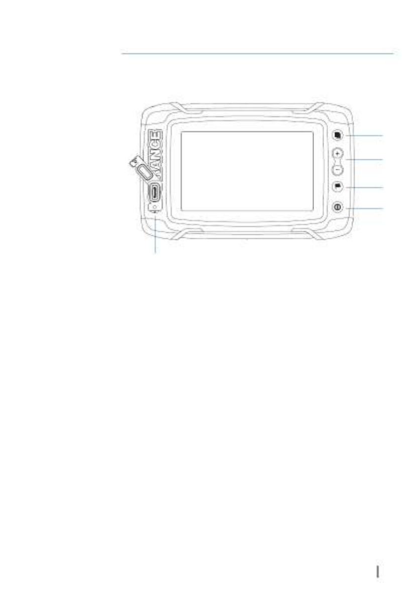
Introduction
Front controls
2
3
4
5
6
1
1 Touch screen
2 Pages
3 Zoom out / Zoom in (combined press = MOB)
4 New waypoint (long press = Find dialogue)
5 Power button
Press and hold to turn the unit ON/OFF.
Press once to display the System Controls dialog.
6 Card reader (behind logo)
1
Introduction | ELITE Ti Operator Manual 13
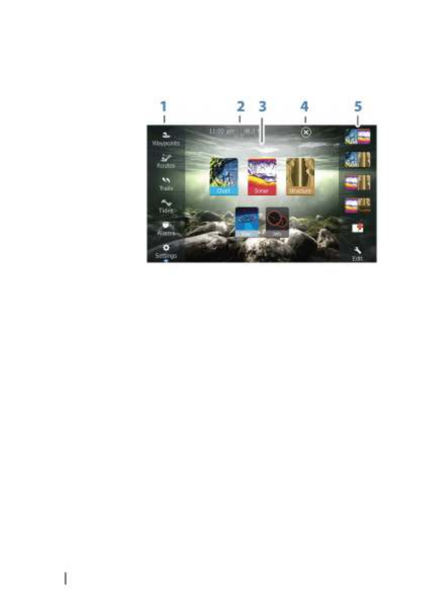
The Home page
The page is accessed from any operation by a short press onHome
the key.Pages
1 Tools
Select a button to access dialogs used for carrying out a
task, or for browsing stored information.
2 Local time Water depth and
3 Applications
Select a button to display the application as a full page
panel.
Press and hold a button to display pre-configured split
page options for the application.
4 Close button
Select to exit the page and return to the previousHome
active page.
5 Favorites
Select a button to display the panel combination.
Press and hold a favorite button to enter edit mode for the
Favorites panel.
14 Introduction | ELITE Ti Operator Manual
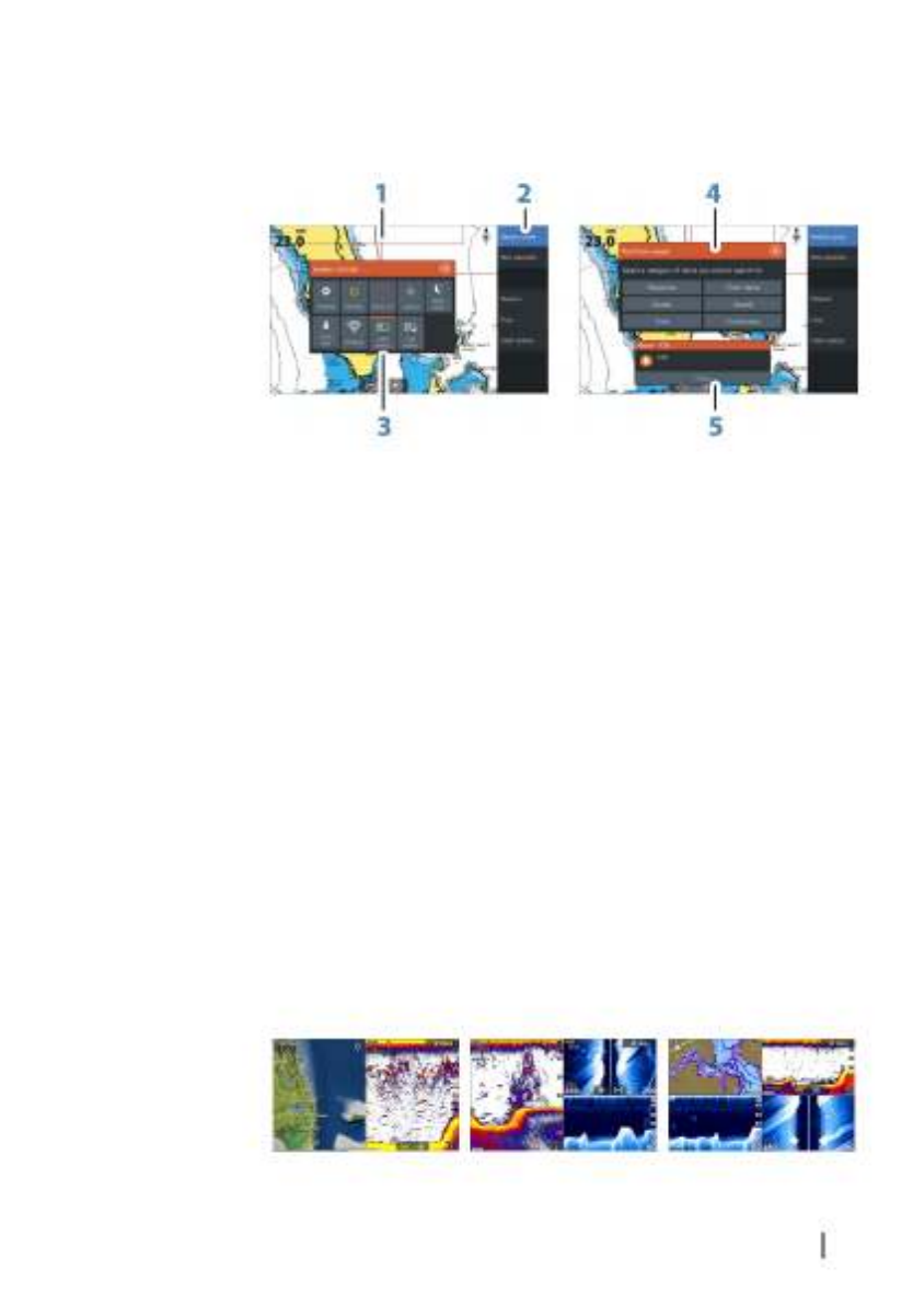
Application pages
Each application connected to the system is presented on panels.
The application can be presented as a full page, or in combination
with other panels in a multiple panel page.
All application pages are accessed from the page.Home
1 Application panel
2 Menu
Panel specific menu.
3 System Controls dialog
Quick access to basic system settings. Display the dialog by
a short press on the key.Power
4 Dialog
Information to or input from the user.
5 Alarm message
Displayed if dangerous situations or system faults occur.
Split pages
You can have up to 4 panels on each page.
2 panels page 3 panels page 4 panels page
Introduction | ELITE Ti Operator Manual 15

Panel sizes in a split page can be adjusted from the System
Controls dialog.
Quick split pages
Each full screen application has several pre-configured quick split
pages, featuring the selected application combined with each of
the other panels.
ÚNote: The number of quick split pages cannot be changed, and
the pages cannot be customized or deleted.
Access a page by pressing and holding the quick split application
button on the page.Home
Favorite pages
All preconfigured favorite pages can be modified and deleted, and
you can create your own. You can have a total of 12 favorite pages.
For more information, refer to on page 26."Adding new favorite pages"
Power-Pole anchors
Power-Pole anchors, which can be controlled by the C-Monster
Control System installed on your boat, can be controlled from the
ELITE Ti. To control the Power-Poles, you the Power-Poles withpair
the ELITE Ti using Bluetooth wireless technology available in both
products.
Power-Pole controls
When Power-Poles are paired with the ELITE Ti, the Power-Pole
button becomes available in the System Controls dialog. Select it to
display the Power-Pole controller.
For pairing Bluetooth devices, refer to on page"Pairing Bluetooth devices"
93. If you are pairing dual Power-Poles, also review "Pairing with dual
Power-Poles" on page 94.
16 Introduction | ELITE Ti Operator Manual

When the Power-Pole controller is opened, the system connects to
paired Power-Poles. When the connection is confirmed the control
buttons are enabled.
ÚNote: The controls are grayed out until the system connects
with the Power-Poles. Once connected and functional the
arrows in the dialog turn white.
The Power-Pole controller displays control buttons for each Power-
Pole that is paired to the ELITE Ti.
Single press the Auto buttons to raise and lower the Power-Poles
automatically all the way up and down. The manual up and down
buttons raise and lower them as quickly, and as high or low as you
want.
Single Power-Pole controller
Dual Power-Poles controller
On a dual controller you can raise and lower the Power-Poles
separately, or press the sync (links) button to allow for control of
both with a single press of the auto buttons or the manual up and
down buttons.
Stay connected
Select the Stay connected (cog) button on the Power-Pole
controller to open the Power-Pole settings dialog where you can
select to stay connected to all paired Power-Pole anchors.
ÚNote: Selecting to speeds up access to theStay connected
controls, but the anchors cannot be controlled from another
display when it is selected. Turn off this option to allow
connection from other displays.
Introduction | ELITE Ti Operator Manual 17

18 Introduction | ELITE Ti Operator Manual

Basic operation
System Controls dialog
The System Controls dialog provides quick access to basic system
settings. You display the dialog by making a short press on the
Power key.
Activating functions
Select the icon of the function you want to set or toggle on or off.
For those functions that toggle on and off, an orange bar across the
top of the icon indicates the function is activated, as shown in the
Data Overlay icon above.
Turning the system on and off
You turn the system on and off by pressing and holding the Power
key. You can also turn the unit off from the System Controls
dialog.
If the key is released before the shut-down is completed, thePower
power off process is cancelled.
Standby mode
In Standby mode, the Sonar and the backlight for screen and keys
are turned off to save power. The system continues to run in the
background.
You select Standby mode from the dialog.System Controls
Switch from Standby mode to normal operation by a short press on
the key.Power
2
Basic operation | ELITE Ti Operator Manual 19
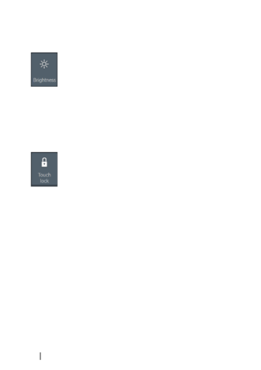
Display illumination
Brightness
The display backlighting can be adjusted at any time from the
System Controls dialog.
You can also cycle the preset backlight levels by short presses on
the key.Power
Night mode
The night mode option optimizes the color palette and backlight for
low light conditions.
ÚNote: Details on the chart may be less visible when the Night
mode is selected!
Locking the touchscreen
You can temporarily lock a touchscreen to prevent accidental
operation of the system. Lock the touchscreen when large amounts
of water are on the screen, for example, in heavy seas and weather.
This feature is also useful when cleaning the screen while the unit is
turned on.
When the touch lock is active you can only operate the unit from
the keys.
You lock the touchscreen from the dialog.System Controls
You remove the lock function by a short press on the key.Power
Using menus and dialogs
Menus
The menu is used to operate the system and to adjust settings.
•Activate a menu item and toggle on/off an option by selecting it
•Adjust a slide bar value by either:
- dragging the slide bar
- selecting the or icons+ -
Select the menu option to return to the previous menu level,Back
and then exit.
Page menus can be hidden to allow pages to be a full screen view.
To hide the menu, drag the menu to the right.
20 Basic operation | ELITE Ti Operator Manual
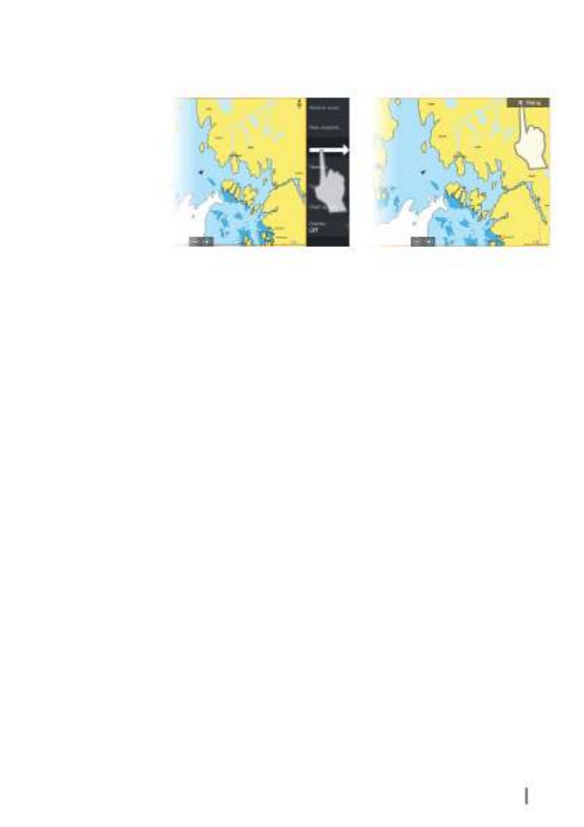
When you hide a menu on one page, the menu on other pages is
also hidden. To display the menu again, select the menu option.
The status of the cursor (active vs. inactive) changes the menu
options.
Dialog boxes
Numeric and alphanumeric keyboards are automatically displayed
when required for entering user information in dialogs.
A dialog is closed by saving or cancelling the entry.
A dialog can also be closed by selecting the in the dialog's upperX
right corner.
Selecting pages and panels
Selecting a page
•Select a full page panel by selecting the relevant application
button on the pageHome
•Select a favorite page by selecting the relevant favorite button
•Select a predefined split panel by pressing and holding the
relevant application icon
Select active panel
In a multiple panel page, only one panel can be active at a time. The
active panel is outlined with a border.
You can only access the page menu of an active panel.
You activate a panel by tapping it.
Using the cursor on the panel
The cursor can be used to measure a distance, to mark a position,
and to select items.
Basic operation | ELITE Ti Operator Manual 21

By default, the cursor is not shown on the panel.
Position the cursor by tapping the desired location on the screen.
When the cursor is active, the cursor position window is displayed.
To remove the cursor and cursor elements from the panel, select
the option.Clear cursor
GoTo cursor
You can navigate to a selected position on the image by positioning
the cursor on the panel, then using the option in theGoto Cursor
menu.
The Cursor assist function
The cursor assist function allows for fine tuning and precision
placement of the cursor without covering details with your finger.
Press and hold your finger on the screen to switch the cursor
symbol to a selection circle, appearing above your finger.
Without removing your finger from the screen, drag the selection
circle over the desired item to display item information.
When you remove your finger from the screen the cursor reverts to
normal cursor operation.
Measuring distance
The cursor can be used to measure the distance between your
vessel and a selected position, or between 2 points on the chart
panel.
1. Position the cursor on the point from where you want to
measure the distance. Start the measure function from the
menu
22 Basic operation | ELITE Ti Operator Manual

- The measuring icons appear with a line drawn from the vessel
center to the cursor position, and the distance is listed in the
cursor information window.
2. You can reposition the measuring points by dragging either
icon as long as the measuring function is active
ÚNote: The bearing is always measured from the grey icon to the
blue icon.
You can also start the measuring function without an active cursor.
Both measuring icons are then initially located at the vessel position.
The grey icon follows the vessel as the vessel moves, while the blue
icon remains at the position given when you activated the function.
You terminate the measuring function by selecting the Finish
measuring menu option.
Creating a Man Overboard waypoint
If an emergency situation should occur, you can save a Man
Overboard (MOB) waypoint at the vessel’s current position by
pressing the ( ) and ( ) keys simultaneously.Zoom In + Zoom out -
When you activate the MOB function the following actions are
automatically performed:
•a MOB waypoint is created at the vessel’s position
•the display switches to a zoomed chart panel, centered on the
vessel's position
•the system displays navigation information back to the MOB
waypoint
Multiple MOB waypoints are saved by repeatedly pressing the MOB
buttons. The vessel continues to show navigation information to
the initial MOB waypoint. Navigation to subsequent MOB waypoints
needs to be done manually.
Cancel navigation to MOB
The system continues to display navigational information towards
the MOB waypoint until you cancel the navigation from the menu.
Display MOB waypoint information
You can display MOB information by selecting the MOB waypoint
and then the MOB waypoint pop-up.
Basic operation | ELITE Ti Operator Manual 23

The MOB waypoint menu option
When an MOB waypoint is activated, you can use the Waypoint
MOB menu option to:
•Move it on the panel
•Edit its attributes
•Delete it
•Goto it
When you select the Edit menu option the Edit Waypoint dialog
opens.
Screen capture
Simultaneously press the and keys to take a screenPages Power
capture. Screen captures are saved to internal memory.
To view files, refer to on page 111."Files"
24 Basic operation | ELITE Ti Operator Manual

Customizing your system
Customizing the Home page wallpaper
The Home page's wallpaper can be customized. You can select one
of the pictures included with the system, or you can use your own
picture in .jpg or .png format.
The images can be available on any location that can be seen in the
files browser. When a picture is chosen as the wallpaper, it is
automatically copied to the Wallpaper folder.
Adjusting panel size
You can change the panel size for an active split page. The panel
size can be adjusted for both favorite pages and for predefined split
pages.
1. Activate the dialogSystem Controls
2. Select the adjust splits option in the dialog
3. Adjust the panel size by dragging the adjustment icon
4. Confirm your changes by tapping one of the panels or selecting
the save option in the menu.
3
Customizing your system | ELITE Ti Operator Manual 25

The changes are saved to the active favorite or split page.
Data Overlay
You can have data information as overlay on a page. The
information can be any data available on the network.
Turning Data overlay on and off
You can turn overlay data on or off for any active page by selecting
the icon on the dialog. When DataData overlay System Controls
overlay is on, an orange bar appears above the icon.
Edit overlay data
Use the option on the dialog toEdit overlay System Controls
access edit menu options to:
•Add a new data overlay to the active panel.
•Delete a selected data overlay.
•Change a selected data overlay to display different data.
•Configure a selected data overlay appearance (digital or analog,
size, etc).
•Re-locate an item by selecting and moving it.
Adding new favorite pages
1. Select the icon in the favorite panel on the page toNew Home
open the page editor dialog
26 Customizing your system | ELITE Ti Operator Manual
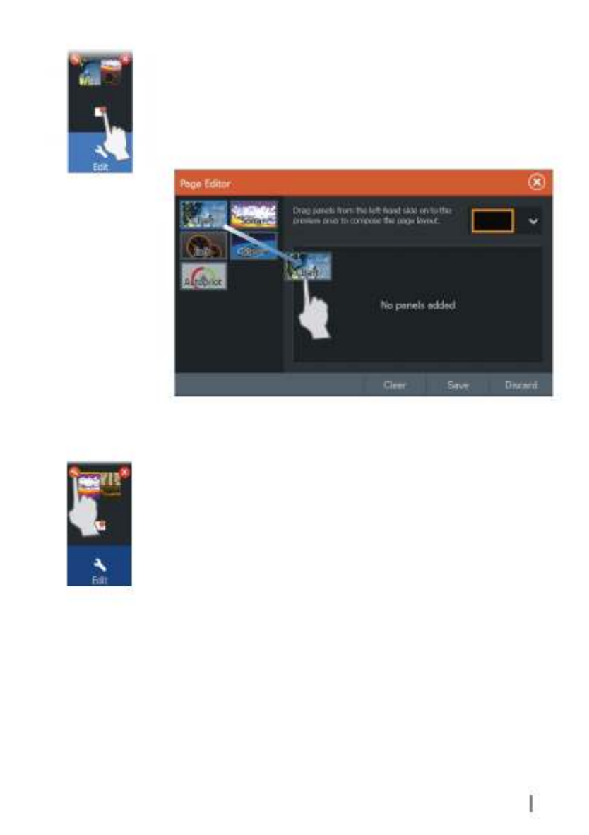
2. Drag and drop page icons to set up a new page
3. Change the panel arrangement (only possible for 2 or 3 panels),
if required
4. Save the page layout.
The system displays the new favorite page, and the new page is
included in the list of favorite pages on the page.Home
Edit favorite pages
1. Select the edit icon in the Favorite panel:
- Select the X icon on a favorite icon to remove the page
- Select the tool icon on a favorite icon to display the page
editor dialog
2. Add or remove panels in the page editor dialog
3. Save or discard your changes to leave the favorite edit mode.
Customizing your system | ELITE Ti Operator Manual 27

Charts
The chart function displays your vessel’s position relative to land
and other chart objects. On the chart panel you can plan and
navigate routes, place waypoints, and display AIS targets.
You can also overlay a StructureScan image.
The Chart panel
1Waypoint*
2Vessel with extension line (extension line is optional)
3Route*
4North indicator
5Grid lines*
6Range rings*
7Trail*
8Chart range scale
9Range rings interval (only displayed when Range rings are
turned on)
4
28 Charts | ELITE Ti Operator Manual

* Optional chart items. You turn the optional chart items on/off
individually from the Chart settings dialog.
Chart data
The system is delivered with different embedded cartography
depending on region.
All units support Insight charts from Navico including Insight
Genesis. The system also supports charts from Navionics and C-MAP
as well as content created by a variety of third party mapping
providers in the AT5 format. For a full selection of available charts,
visit www.gofreeshop.com, www.c-map.com, or
www.navionics.com.
ÚNote: In this manual, all possible chart menu options are
described. These options vary depending on the chart you are
using.
ÚNote: Insight charts are referred to as Lowrance in the menu.
ÚNote: The system does not automatically switch to embedded
cartography if the chart card is removed. A low-resolution chart
will be displayed until you re-insert the card or manually switch
back to the embedded cartography.
Selecting chart type
You specify the chart type in the Chart panel by selecting one of the
available chart types in the chart source menu option.
Vessel symbol
When the system has a valid GPS position lock, the vessel symbol
indicates vessel position. If no GPS position is available, the vessel
symbol includes a question mark.
ÚNote: Without a heading sensor on the network, the vessel icon
orientates itself using COG (Course over Ground).
Chart scale
You zoom in and out on the chart by using the zoom (+ or -)
buttons or the and keys.+ -
Charts | ELITE Ti Operator Manual 29
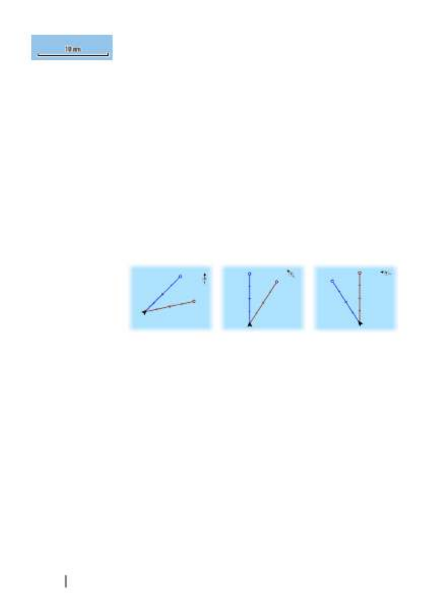
Chart range scale and range rings interval (when turned on) are
shown in the lower right corner of the chart panel.
Panning the chart
You can move the chart in any direction by dragging your finger on
the screen.
Select the menu option to remove the cursor andClear cursor
cursor window from the panel. This also centers the chart to the
vessel position.
Positioning the vessel on the chart panel
Chart orientation
Several options are available for how the chart is rotated in the
panel. The chart orientation symbol in the panel’s upper right
corner indicates the north direction.
North up Heading up Course up
North up
Displays the chart with north upward.
Heading up
Displays the chart with the vessel’s heading directed upward.
Heading information is received from a compass. If heading is not
available, then the COG from the GPS is used.
Course up
Displays the chart with the direction the vessel is ACTUALLY
traveling directed upward, which in some cases is not the direction
the vessel is headed.
Look ahead
Moves the vessel icon closer to the bottom of the screen so that
you can maximize your view ahead.
30 Charts | ELITE Ti Operator Manual
1. Position the cursor on the chart panel
2. Select followed by in the menuNew New route
3. Continue positioning the remaining routepoints
4. Save the route by selecting the save option in the menu.
ÚNote: For more information, refer to on"Waypoints, Routes, and Trails"
page 45.
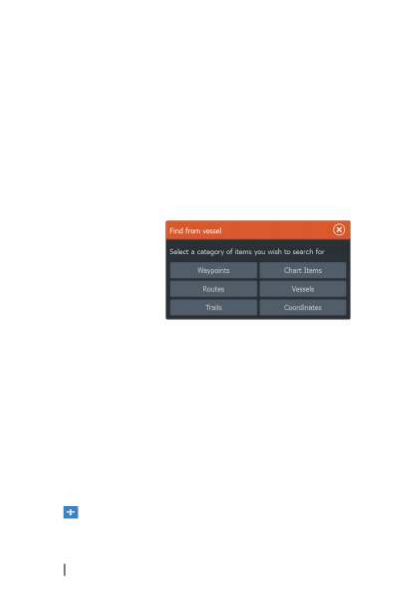
Find objects on chart panels
You can search for other vessels or various chart items from a chart
panel.
Activate the cursor on the panel to search from the cursor position.
If the cursor is not active, the system searches for items from the
vessel's position.
ÚNote: You must have an AIS receiver connected to search for
vessels.
3D charts
The 3D option provides a three dimensional graphical view of land
and sea contours.
ÚNote: All chart types work in 3D mode, but without 3D
cartography for the appropriate area the chart appears flat.
When the 3D chart option is selected, the Pan and the Rotate icons
appear on the chart panel.
Panning the 3D chart
You can move the chart in any direction by selecting the Pan icon
and then panning in the desired direction.
32 Charts | ELITE Ti Operator Manual

Select the menu option to stop panning, and toReturn to vessel
center the chart to vessel position.
Controlling the view angle
You can control the view angle by selecting the Rotate icon and
then panning the chart panel.
•To change the direction you are viewing, pan horizontally
•To change the tilt angle of the view, pan vertically
ÚNote: When centered on the vessel position, only the tilt angle
can be adjusted. The view direction is controlled by the chart
orientation setting. See on page"Positioning the vessel on the chart panel"
30.
Zooming a 3D chart
You zoom in and out on a 3D chart by using the zoom (+ or -)
buttons or by using the and keys.+ -
Chart overlay
Structure (StructureMap) information can be displayed as overlay on
your chart panel.
When an overlay is selected, the chart menu expands to include
basic menu functions for the selected overlay.
For more information about the StructureMap menu functions, refer
to on page 78."Structure options"
Insight and C-MAP charts
All possible menu options for Insight and C-MAP charts are
described below. The features and menu options available can vary
depending on the charts you use. This section shows menus from
an Insight chart.
ÚNote: A menu option is greyed out if it is not available on the
chart displayed. For example, raster charts are not available with
Insight, so the Raster charts menu option is greyed out when
Insight charts are displayed.
Charts | ELITE Ti Operator Manual 33
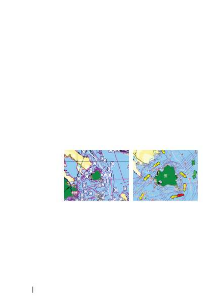
Insight and C-MAP tides and currents
The system can display Insight and C-MAP tides and currents. With
this information it is possible to predict the time, level, direction and
strength of currents and tides. This is an important tool when
considering planning and navigation of a trip.
In large zoom ranges the tides and currents are displayed as a
square icon including the letter (Tides) or (Current). When youT C
select one of the icons, tidal or current information for that location
are displayed.
Dynamic current data can be viewed by zooming inside a 1-nautical
mile zoom range. At that range, the Current icon changes to an
animated dynamic icon that shows the speed and direction of the
current. Dynamic icons are colored in black (greater than 6 knots),
red (greater than 2 knots and less than or equal to 6 knots), yellow
(greater than 1 knot and less than or equal to 2 knots) or green
(equal to or less than 1 knot), depending on the current in that
location.
If there is no current (0 knots) this will be shown as a white, square
icon.
Static Current and Tide icons Dynamic Current icons
34 Charts | ELITE Ti Operator Manual
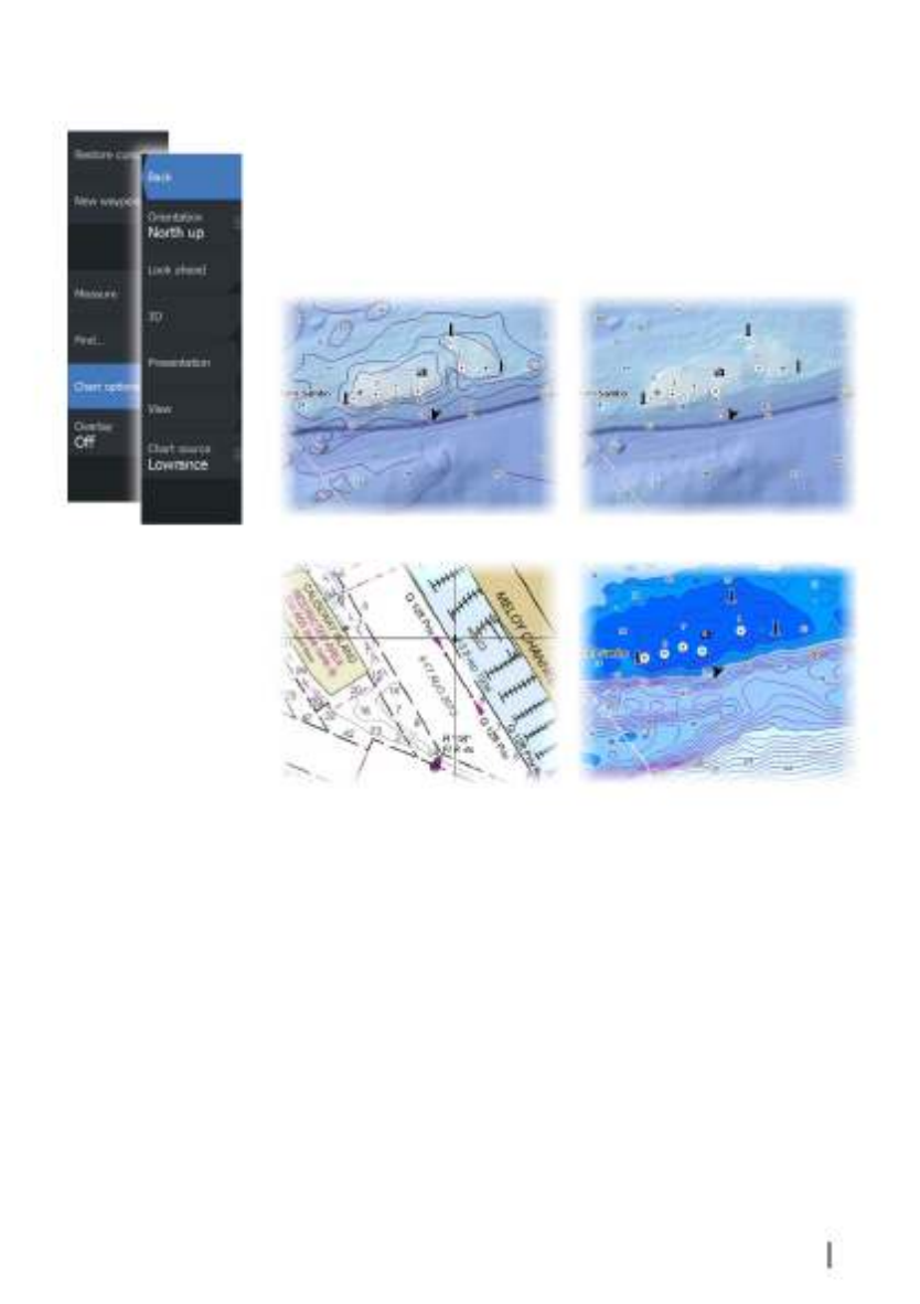
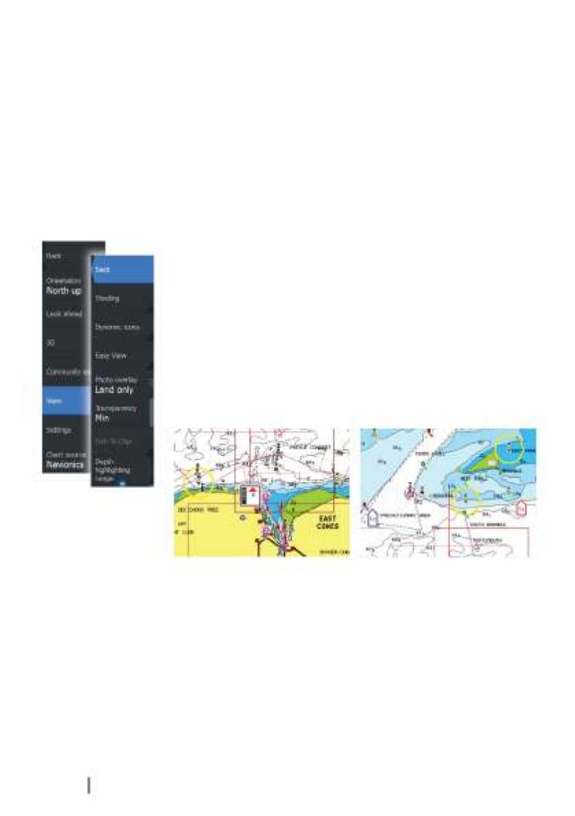
Insight and C-MAP specific chart options
Orientation, Look ahead, 3D, and change Chart source (previously
described in this section) are common for all chart types.
Presentation
The charts can be displayed in different imagery styles.
Shaded relief No contours
Raster imagery High resolution bathymetry
Charts | ELITE Ti Operator Manual 35

Shaded relief
Shades seabed terrain.
No contours
Removes contour lines from the chart.
Raster charts
Changes the view to that of a traditional paper chart.
Raster transparency
Controls the transparency of raster imagery.
High resolution bathymetry
Enables and disables higher concentration of contour lines.
Insight and C-MAP view options
Chart detail
•Full
All available information for the chart in use.
•Medium
Minimum information sufficient for navigation.
•Low
Basic level of information that cannot be removed, and includes
information that is required in all geographic areas. It is not
intended to be sufficient for safe navigation.
Insight and C-MAP chart categories
Insight and C-MAP charts include several categories and sub-
categories that you can turn on/off individually depending on
which information you want to see.
Photo overlay
Photo overlay enables you to view satellite photo images of an area
as an overlay on the chart. The availability of such photos is limited
to certain regions, and cartography versions.
You can view photo overlays in either 2D or 3D modes.
36 Charts | ELITE Ti Operator Manual

No Photo overlay Photo overlay, land only Full Photo overlay
Photo transparency
The Photo transparency sets the opaqueness of the photo overlay.
With minimum transparency settings the chart details are almost
hidden by the photo.
Minimum transparency Transparency at 80
Depth palette
Controls the Depth palette used on the map.
Paper chart
Changes the appearance of the map to a paper chart style.
Safety depth
Insight and C-MAP charts use different shades of blue to
distinguish between shallow (lighter shades) and deep (darker
shades) water. After enabling Safety depth, specify the
desired safety depth limit. The Safety depth sets the limit at which
depths will be drawn without blue shading.
Depth filter
Filters out depth values shallower than the selected depth filter
limit.
Charts | ELITE Ti Operator Manual 37

Shading
Shades different areas of the seabed, depending on the selected
Shading category.
ÚNote: Composition and Vegetation shading are not applicable
to C-MAP charts.
Depth 1 and Depth 2
Depth presets that shade different depths in different colors.
Custom
You can adjust the depth threshold, color and opacity
(transparency) of color shading for Depth 1 and Depth 2.
3D exaggeration
Graphical settings that are available in 3D mode only. Exaggeration
is a multiplier applied to the drawn height of hills on land, and
troughs in water to make them look taller or deeper.
ÚNote: This option is grayed out if the data is not available in the
map card inserted.
Navionics charts
38 Charts | ELITE Ti Operator Manual

Navionics specific chart options
Orientation, Look ahead, 3D and change Chart source (previously
described in this section) are common for all chart types.
Community edits
Toggles on the chart layer including Navionics edits. These are user
information or edits uploaded to Navionics Community by users,
and made available in Navionics charts.
For more information, refer to Navionics information included with
your chart, or to Navionics website: www.navionics.com.
Navionics chart settings
Colored seabed areas
Used for displaying different depth areas in different shades of blue.
Annotation
Determines what area information, such as names of locations and
notes of areas, is available to display.
Presentation type
Provides marine charting information such as symbols, colors of the
navigation chart and wording for either International or U.S.
presentation types.
Chart details
Provides you with different levels of geographical layer information.
Safety depth
The Navionics charts use different shades of blue to distinguish
between shallow and deep water.
Safety depth, based on a selected limit, is drawn without blue
shading.
ÚNote: The built in Navionics database features data down to 20
m, after which it is all white.
Charts | ELITE Ti Operator Manual 39
Contours depth
Determines which contours you see on the chart down to the
selected safety depth value.
Rock filter level
Hides rock identification on the chart beneath a given depth.
This helps you to declutter charts in areas where there are many
rocks located at depths well below your vessel's draught.
Navionics view options
Chart shading
Shading adds terrain information to the chart.
Navionics dynamic tide and current icons
Shows tides and currents with a gauge and an arrow instead of the
diamond icons used for static tides and current information.
The tide and current data available in Navionics charts are related to
a specific date and time. The system animates the arrows and/or
gauges to show the tides and currents evolution over time.
Dynamic tide information Dynamic current information
The following icons and symbology are used:
40 Charts | ELITE Ti Operator Manual

Current speed
The arrow length depends on the rate, and the
symbol is rotated according to flow direction. Flow
rate is shown inside the arrow symbol. The red
symbol is used when current speed is increasing,
and the blue symbol is used when current speed is
decreasing.
Tide height
The gauge has 8 labels and is set according to
absolute max/min value of the evaluated day. The
red arrow is used when tide is rising, and the blue
arrow is used when tide is falling.
ÚNote: All numeric values are shown in the relevant system units
(unit of measurement) set by user.
Easy View
Magnifying feature that increases the size of chart items and text.
ÚNote: There is no indication on the chart showing that this
feature is active.
Photo overlay
Photo overlay enables you to view satellite photo images of an area
as an overlay on the chart. The availability of such photos is limited
to certain regions, and cartography versions.
You can view photo overlays in either 2D or 3D modes.
No Photo overlay Photo overlay, land only Full Photo overlay
Photo transparency
The Photo transparency sets the opaqueness of the photo overlay.
With minimum transparency settings the chart details are almost
hidden by the photo.
Charts | ELITE Ti Operator Manual 41

Minimum transparency Maximum transparency
Navionics Fish N' Chip
The system supports Navionics Fish N' Chip chart feature.
For more information, see www.navionics.com.
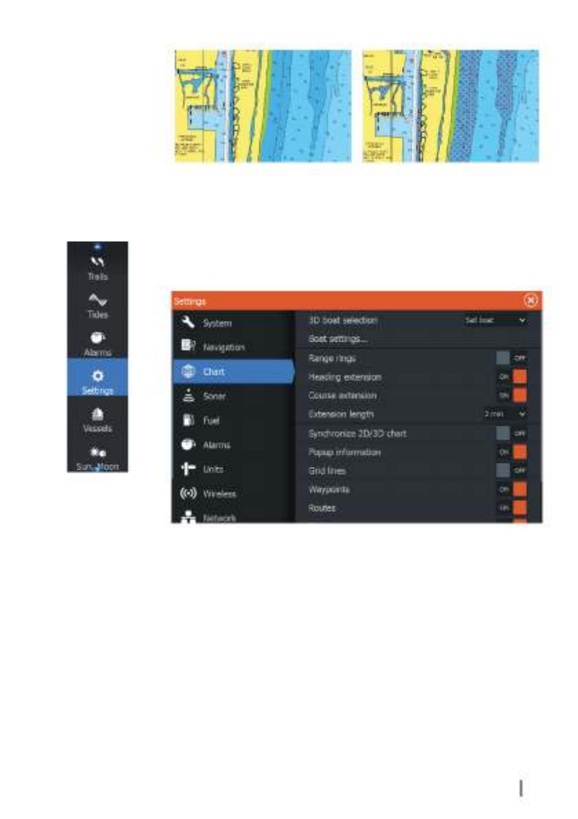
Depth highlight range
Select a range of depths between which Navionics fills with a
different color.
This allows you to highlight a specific range of depths for fishing
purposes. The range is only as accurate as the underlying chart data,
meaning that if the chart only contains 5 meter intervals for contour
lines, the shading is rounded to the nearest available contour line.
No Depth highlight range Depth highlight range: 6 m - 12 m
Shallow water highlight
Highlights areas of shallow water.
This allows you to highlight areas of water between 0 and the
selected depth (up to 10 meters/30 feet).
42 Charts | ELITE Ti Operator Manual
No shallow water highlighted Shallow water highlight: 0 m - 3 m
Chart settings
Settings and display options made in the Chart settings page are
common for all chart panels.
3D boat selection
Determines which icon to use on 3D charts.
Boat settings
Not used.
Range Rings
The range rings can be used to present the distance from your
vessel to other chart objects.
Charts | ELITE Ti Operator Manual 43

The range scale is set automatically by the system to suit the chart
scale.
Extension lines
Sets the lengths of the heading and course extension lines for your
vessel. For setting extension line lengths on other vessels shown as
AIS targets, refer to AIS on page 103 lines."Course extension lines"
A: Heading
B: Course Over Ground (COG)
The lengths of the extension lines are either set as a fixed distance,
or to indicate the distance the vessel moves in the selected time
period. If no options are turned on for the vessel then no extension
lines are shown for your vessel.
Your vessel heading is based on information from the active
heading sensor and the COG is based on information from the
active GPS sensor.
Synchronize 2D/3D chart
Links the position shown on one chart with the position shown on
the other chart when a 2D and a 3D chart are shown side by side.
Pop-up information
Selects whether basic information for chart items is displayed when
you select the item.
Grid lines
Turns on/off viewing of longitude and latitude grid lines on the
chart.
Hide chart
If the option is set to ON when viewing a Lowrance chart, the chart
(background) is not displayed and only the vessel, extensions,
waypoints, and routes are displayed on a white background.
Waypoints, Routes, Trails
Turns on/off displaying of these items on chart panels. Also opens
the Waypoints, Routes and Trails dialogs you can use to manage
them.
44 Charts | ELITE Ti Operator Manual

Waypoints, Routes, and Trails
Waypoints, Routes, and Trails dialogs
The Waypoints, Routes, and Trails dialogs give access to advanced
edit functions and settings for these items.
The dialogs are accessed from the on the page.Tools panel Home
Waypoints
A waypoint is a user generated mark positioned on a chart, or on
the Sonar image. Each waypoint has an exact position with latitude
and longitude coordinates. A waypoint positioned on the Sonar
image has a depth value, in addition to position information. A
waypoint is used to mark a position you later may want to return to.
Two or more waypoints can also be combined to create a route.
5
Waypoints, Routes, and Trails | ELITE Ti Operator Manual 45

Saving waypoints
You can save a waypoint at a selected location by positioning the
cursor on the panel, and then selecting the new waypoint option in
the menu.
You can also save a waypoint by pressing the Waypoint key:
•Press once to display the New Waypoint dialog
•Press twice to quickly save a waypoint. If the cursor is active, the
waypoint is saved at the cursor position. If the cursor is not active,
the waypoint is saved at your vessel's position.
Moving a waypoint
1. Select the waypoint you want to move. The waypoint icon
expands to indicate that it is active.
2. Activate the menu and select the waypoint in the menu
3. Select the move option
4. Select the new waypoint position
5. Select Finish in the menu.
The waypoint is now automatically saved at the new position.
Edit a waypoint
You can edit all information about a waypoint from the Edit
Waypoint dialog.
The dialog can also be accessed from the Waypoints tool on the
Home page.
46 Waypoints, Routes, and Trails | ELITE Ti Operator
Manual

Delete a waypoint
You can delete a waypoint from the dialog or byEdit Waypoint
selecting the menu option when the waypoint is activated.Delete
You can also delete waypoints from the Waypoints tool on the
Home page.
You can delete MOB waypoints the same way.
Waypoint alarm settings
You can set an alarm radius for each individual waypoint you create.
The alarm is set in the dialog.Edit Waypoint
ÚNote: The waypoint radius alarm must be toggled ON in the
alarm dialog to activate an alarm when your vessel comes
within the defined radius. For more information, refer to "Alarms
dialog" on page 105.
Routes
A route consists of a series of routepoints entered in the order that
you want to navigate them.
When you select a route on the chart panel it turns green, and the
route name is displayed.
Creating a new route on the chart panel
1. Activate the cursor on the chart panel
2. Select the new route option from the menu
3. Position the first waypoint on the chart panel
4. Continue positioning new routepoints on the chart panel until
the route is completed
5. Save the route by selecting the save option in the menu.
Waypoints, Routes, and Trails | ELITE Ti Operator Manual 47

Edit a route from the chart panel
1. Select the route to make it active.
2. Select the route edit option in the menu.
3. Position the new routepoint on the chart panel:
- If you set the new routepoint on a leg, a new point is added
between existing routepoints.
- If you set the new routepoint outside the route, the new
routepoint is added after the last point in the route.
4. Drag a routepoint to move it to a new position.
5. Save the route by selecting the save option in the menu.
ÚNote: The menu changes depending on the selected edit
option. All edits are confirmed or cancelled from the menu.
Delete a route
You can delete a route by selecting the menu option whenDelete
the route is activated. You can also delete routes from the Routes
tool on the page.Home
Creating routes using existing waypoints
You can create a new route by combining existing waypoints from
the dialog. The dialog is activated by using the toolRoutes Routes
on the page.Home
48 Waypoints, Routes, and Trails | ELITE Ti Operator
Manual

Converting Trails to Routes
You can convert a trail to a route from the Edit Trail dialog. The
dialog is activated by activating the trail, then selecting the trail's
pop-up, or the menu option. Trail
The Edit Trails dialog can also be accessed by selecting the Trails
tool on the page.Home
The Edit Route dialog
You can add and remove routepoints from the dialog.Edit Route
This dialog is activated by selecting an active route's pop-up or from
the menu.
The dialog can also be accessed by using the tool on theRoutes
Home page.
Waypoints, Routes, and Trails | ELITE Ti Operator Manual 49
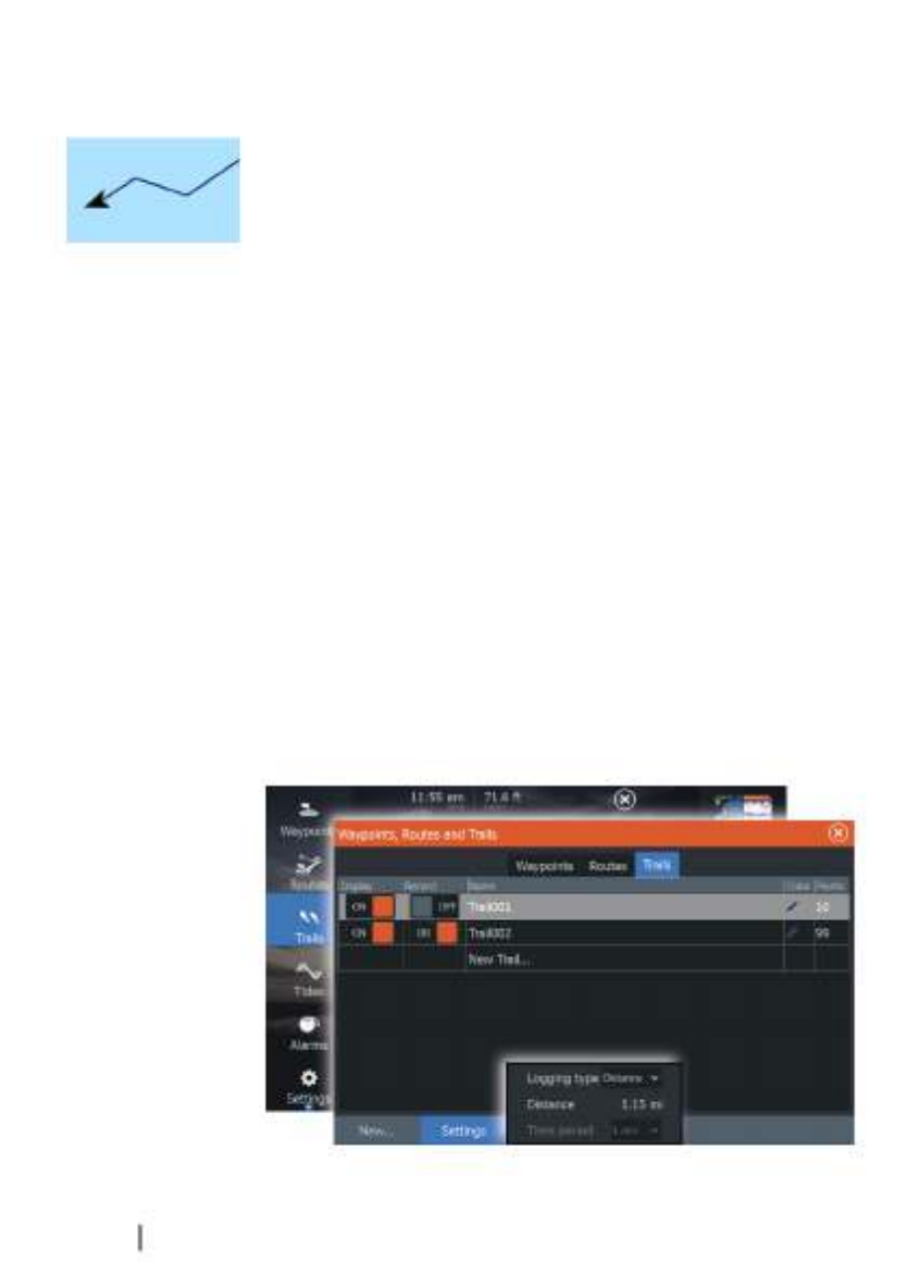
Trails
Trails are a graphical presentation of the historical path of the vessel,
allowing you to retrace where you have travelled. Trails can be
converted to routes from the dialog.Edit
From the factory, the system is set to automatically track and draw
the vessel's movement on the chart panel. The system continues to
record the Trails until the length reaches the maximum points, and
then automatically begins overwriting the oldest points.
The automatic tracking function can be turned off from the Trails
dialog.
Creating new Trails
You can start a new trail from the dialog, activated by usingTrails
the tool on the page.Trails Home
Trails settings
Trails are made up of a series of points connected by line segments
whose length depends on the frequency of the recording.
You can select to position trail points based on time settings,
distance, or by letting the system position a waypoint automatically
when a course change is registered.
ÚNote: The Trails option must also be turned ON in the chart
settings to be visible.
50 Waypoints, Routes, and Trails | ELITE Ti Operator
Manual

Navigating
The navigation function included in the system allows you to
navigate to the cursor position, to a waypoint, or along a predefined
route.
If autopilot functionality is included in your system, the autopilot
can be set to automatically navigate the vessel.
For information about positioning waypoints and creating routes,
refer to on page 45."Waypoints, Routes, and Trails"
Steer panel
The Steer panel can be used to display information when you are
navigating. It is activated from the page, either as a full pageHome
panel or as part of a multiple panel page.
1Data fields
2Vessel heading
3Bearing to waypoint
4Destination point
6
Navigating | ELITE Ti Operator Manual 51

5Bearing line with allowed off course limit
When travelling on a route the bearing line shows the
intended course from one waypoint towards the next.
When navigating towards a waypoint (cursor position, MOB,
or an entered latitude and longitude position), the bearing
line shows the intended course from the point at which
navigation was started towards the waypoint.
6Vessel symbol
Indicates distance and bearing relative to the intended
course. If the XTE (Cross Track Error) exceeds the defined XTE
limit, this is indicated with a red arrow including the
distance from the track line.
Data Fields
The Steer panel provides the following information:
XTE Cross track error
SOG Speed over ground
COG Course over ground
POS Position
DTD Distance to destination
TTD Time to destination
Navigate to cursor position
Position the cursor at the selected destination on the panel, and
then select the option in the menu.Goto Cursor
ÚNote: The menu option is not available if you areGoto Cursor
already navigating.
Navigate a route
When route navigation is started, the menu expands and shows
options for canceling the navigation, for skipping a waypoint, and
for restarting the route from current vessel position.
52 Navigating | ELITE Ti Operator Manual

Starting a route from the chart panel
Activate a route on the panel, and then select the route navigation
option from the menu.
You can select a routepoint to start navigating from a selected
position.
Starting a route from the steer panel
Select the start route option on the menu, and then details from the
dialogs.
Start navigating a route from the Route dialog
You can start navigating from the dialog, activated by:Route
•Selecting the tool from the pageRoute Home
•Selecting the route details from the menu
Navigating with the autopilot
Navigating with the autopilot is available with all units that have set
up the trolling motor autopilot. Autopilot is not available on the
ELITE-5Ti.
When you start navigation on a system with autopilot functionality,
you are prompted to set the autopilot to navigation mode.
Navigating | ELITE Ti Operator Manual 53

If you choose not to engage the autopilot, the autopilot can be set
to navigation mode from the Autopilot Controller later on.
For more information about autopilot functionality, refer to "Autopilot"
on page 82.
Navigation settings
Arrival radius
Sets an invisible circle around the destination waypoint.
The vessel is considered arrived at the waypoint when it is within
this radius.
XTE limit
This setting defines how far the vessel can deviate from the selected
route, if the vessel goes beyond this limit, an alarm is activated.
XTE alarm (Cross track error)
Turns on/off the XTE alarm.
Trails
Opens the dialog where trails settings can be adjusted andTrails
trails can be converted into routes for navigation. Refer to "Converting
Trails to Routes" on page 49.
54 Navigating | ELITE Ti Operator Manual
Logging type
You can select to record trail points based on time, distance, or by
letting the unit position a point automatically when a course
change is registered.
Specify one of the following logging types in the Navigating
Settings dialog:
•Auto - the unit positions a point automatically when a course
change is registered.
•Distance - select the Distance field and enter the distance you
want to record.
•Time - select the Time field and enter the time you want to
record.
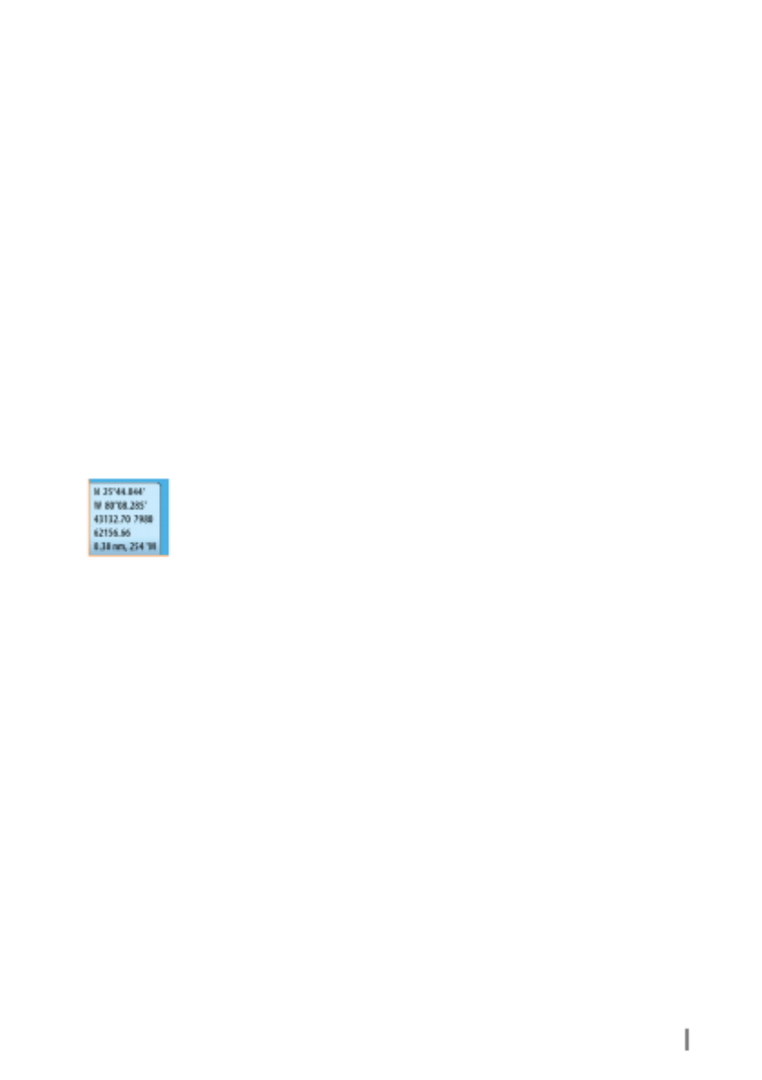
Phantom Loran
Enables use of Phantom Loran positioning system.
Loran settings
Defines Loran chains (GRI) and preferred station for waypoint entry,
cursor position and position panel.
The graphic example shows a cursor position window with Loran
position information.
For more information refer to your Loran system documentation.
Navigating | ELITE Ti Operator Manual 55

Sonar
The Sonar function provides a view of the water and bottom
beneath your vessel, allowing you to detect fish and examine the
structure of the sea floor.
The Sonar image
1Fish arches
2History preview*
3Temperature graph*
4Depth at cursor
5Amplitude scope*
6Zoom (range) buttons
7Water depth and Water temperature at cursor location
8Range scale
9Bottom
* Optional Sonar items that you turn on/off individually.
7
56 Sonar | ELITE Ti Operator Manual

Zooming the image
You can zoom the image by:
•using the zoom (+ or -) buttons
•using the / keys+ -
Zoom level is shown on the bottom left side of the image.
When zooming in, the sea floor is kept near the bottom of the
screen, irrespective of whether it is in auto-range or manual range.
If the range is set considerably less than the actual depth, the unit is
not able to find the bottom when zooming.
If the cursor is active, the unit zooms in where the cursor is pointed.
Zoom bar
The zoom bar is displayed when you zoom the image.
Drag the zoom bar vertically to view different parts of the water
column.
Using the cursor on the image
The cursor can be used to measure a distance to a target, to mark a
position, and to select targets.
By default, the cursor is not shown on the image.
When you position the cursor on the image; the screen pauses, the
depth at the cursor position is shown, and the information window
and the history bar are activated.
To remove the cursor and cursor elements from the panel, select
the menu option.Clear cursor
Viewing history
Whenever the cursor is shown on the Sonar panel, the scroll bar is
shown at the top of the panel. The scroll bar shows the image you
are currently viewing in relation to the total Sonar image history
stored.
If the scroll bar is on the far right side, it indicates that you are
viewing the latest soundings. If you position the cursor to the left
side of the screen, the history bar starts scrolling towards the left,
and the automatic scrolling as new soundings are received is turned
off.
Sonar | ELITE Ti Operator Manual 57

You can view sonar history by panning the image. You can also use
the preview feature to pan history, refer to on page 65."Preview"
To resume normal scrolling, select the menu option.Clear cursor
Setting up the image
Use the Sonar menu options to set up the image. When the cursor
is active, some options on the Sonar menu are replaced with cursor
mode features. Select to return to the normal SonarClear cursor
menu.
The range
The range setting determines the water depth that is visible on the
screen.
Auto range
By default, the range is set to Auto. With Auto, the system
automatically displays the whole range from the water surface to
the bottom. Auto is the preferred setting for most fish finding sonar
use.
Preset range levels
Allows for the selection of a specific depth range that is not tied to
the depth of the water.
Custom range
This option allows you to manually set both upper and lower range
limits.
58 Sonar | ELITE Ti Operator Manual

ÚNote: Setting a custom range puts the sonar in manual mode. If
the bottom is well beyond the lower range set, you may lose
digital depth.
Frequency
The unit supports several transducer frequencies. Available
frequencies depend on the transducer model that is connected.
ÚNote: This unit cannot operate CHIRP frequencies and SideScan
at the same time. If you turn on StructureScan Left/Right view,
you will not be able to use the CHIRP sonar.
You can view two frequencies at the same time by selecting dual
Sonar panels from the page.Home
Sensitivity
Increasing Sensitivity shows more detail on the screen. Decreasing
Sensitivity displays less. Too much detail clutters the screen.
Conversely, desired echoes may not be displayed if Sensitivity is set
too low.
ÚNote: Auto Sensitivity is the preferred mode for most
conditions.
Auto sensitivity
Auto sensitivity automatically adjusts the sonar return to the
optimal levels. Auto sensitivity can be adjusted (+/-) to your
preference while still maintaining the auto sensitivity functionality.
Colorline
Allows the user to adjust the colors of the display to help
differentiate softer targets from harder ones. Adjusting the Colorline
can help separate fish and important structures on or near the
bottom from the actual bottom.
Adjusting Sensitivity and Colorline
Select the Sensitivity or Colorline menu options in the Sonar menu
and adjust them by dragging the bar vertically up/down. Minor
adjustments can be made by tapping on the top or bottom of the
slider bar.
Sonar | ELITE Ti Operator Manual 59
Stop sonar
Select the menu option to stop the sonar from pinging.Stop sonar
Use the stop sonar option anytime you want to disable the sonar
but not power off the unit.
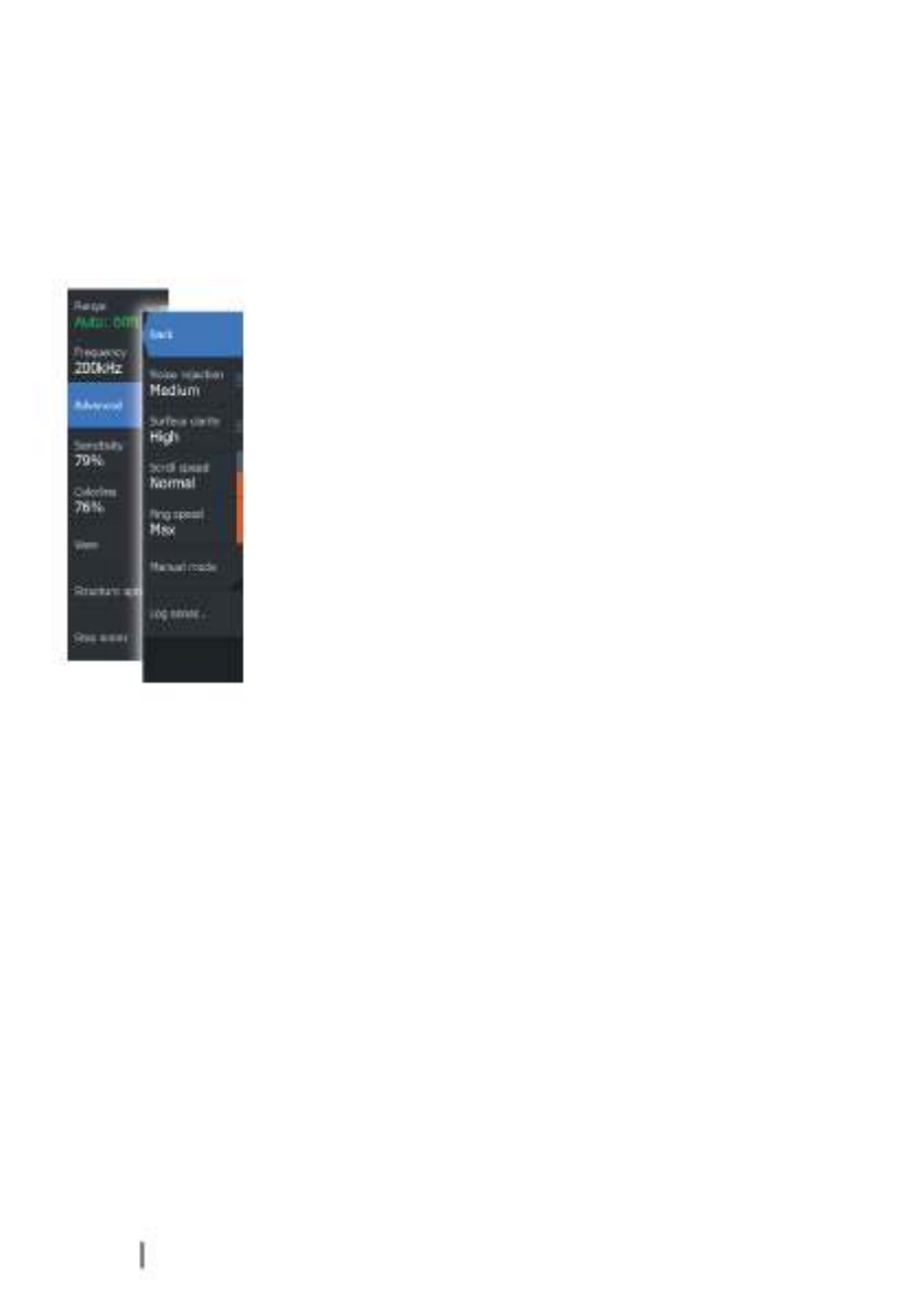
Advanced options
The Advanced option is only available when the cursor is not active.
Noise rejection
Signal interference from bilge pumps, engine vibration and air
bubbles can clutter the image.
The noise rejection option filters the signal interference and reduces
the on-screen clutter.
Surface clarity
Wave action, boat wakes, and temperature inversion can cause
onscreen clutter near the surface. The surface clarity option reduces
surface clutter by decreasing the sensitivity of the receiver near the
surface.
Scroll speed
You can select the scrolling speed of the image on the screen. A
high scroll speed updates the image fast, while a low scroll speed
presents a longer history.
ÚNote: In certain conditions it may be necessary to adjust the
scroll speed to get a more useful image. Such as adjusting the
image to a faster speed when vertically fishing without moving.
Ping speed
Ping speed controls the rate the transducer transmits the Sonar
signal into the water. By default, the ping speed is set to max. It may
be necessary to adjust the ping speed to limit interference or to
adjust for specific fishing conditions.
Manual mode
Manual mode is an advanced user mode that restricts digital depth
capability, so the unit only processes sonar signals in the selected
60 Sonar | ELITE Ti Operator Manual

range. This allows the display to continue smooth scrolling if the
bottom depth is out of transducer range. When the unit is in
manual mode, you might not receive any depth readings, or you
might receive incorrect depth information.
Start recording log data
You can start recording log data and save the file internally in the
unit, or save it onto a card inserted into the unit’s card reader.
The dialog is activated from the menuLog sonar Advanced
option, or from the dialog.Sonar Settings
When the data is being recorded, there is a flashing red symbol in
the top left corner and a message appears periodically at the
bottom of the screen.
Filename
Specify the name of the recording (log).
File format
Select a file format from the drop-down, slg (Sonar only), xtf
(DownScan only*), or sl2 (Sonar and DownScan).
ÚNote: XTF format is for use only with select 3rd party Sonar
viewing tools.
Sonar | ELITE Ti Operator Manual 61

Save to
Select whether the recording is to be saved internally or to a
memory card in the card reader.
Bytes per sounding
Select how many bytes per seconds that are to be used when
saving the log file. More bytes yield better resolution, but cause the
record file to increase in size compared to using lower byte settings.
Create StructureMap
If StructureScan is available on the network, you can convert the .sl2
logs to StructureMap format (.smf) when recording completes. The
log file can also be converted to StructureMap format from the Files
option.
Upload to Insight Genesis
Files are transmitted to Insight Genesis when recording completes,
if you are connected to a wireless hotspot. For information about
wireless hotspots, refer to on page 90."Wireless connection"
Privacy
If allowed by your selected Insight Genesis account, you can choose
between setting the recorded log files as Private or Public at Insight
Genesis.
Time remaining
Shows the remaining allocated space available for recordings.
Stop recording log data
Select in the Logging Sonar dialog to fully stop the recordingStop
of all sonar log data.
ÚNote: If you have selected the Upload to Insight Genesis
option and are connected to a wireless hotspot, your recorded
files are transmitted to Insight Genesis when you select .Stop
62 Sonar | ELITE Ti Operator Manual

Viewing the recorded sounder data
Both internally and externally stored sounder records may be
reviewed when the view sonar log option is selected in the Sonar
settings dialog. Refer to on page 66."Sonar settings"
The log file is displayed as a paused image, and you control the
scrolling and display from the replay menu option.
You can use the cursor on the replay image, and pan the image as
on a normal echo image.
If more than one channel was recorded in the selected echo file,
you can select which channel to display.
You exit the replay mode by selecting the symbol in the upperX
right corner of the replay image.
Sonar | ELITE Ti Operator Manual 63

Sonar view options
Select the View option in the Sonar menu to see View options.
Split screen options
Zoom
1Zoom level
2Zoom bars
The Zoom mode presents a magnified view of the sounder image
on the left side of the panel. By default the zoom level is set to 2x.
You can select up to 8x zoom from the drop-down menu, using the
+ -/ keys, or the zoom (+ or -) buttons. The range zoom bars on the
right side of the display shows the range that is magnified. If you
increase the zooming factor the range is reduced. You see this as
reduced distance between the zoom bars.
Bottom lock
The bottom lock mode is useful when you want to view echoes
close to the bottom. In this mode, the left side of the panel shows
an image where the bottom is flattened. The range scale is changed
to measure from the seabed (0) and upwards. The bottom and the
zero line are always shown on the left image, independent of the
range scale. The scaling factor for the image on the left side of the
panel is adjusted as described for the Zoom option.
64 Sonar | ELITE Ti Operator Manual

Flasher
The Flasher mode shows a flasher-style sonar view in the left panel
and a normal sonar view in the right panel.
Palettes
You can select between several display palettes optimized for a
variety of fishing conditions.
Temperature graph
The temperature graph is used to illustrate changes in water
temperature.
When toggled on, a colored line and temperature digits are shown
on the Sonar image.
Depth line
A depth line can be added to the bottom surface to make it easier
to distinguish the bottom from fish and structures.
Amplitude scope
The Amplitude scope is a display of real-time echoes as they appear
on the panel. The strength of the actual echo is indicated by both
width and color intensity.
Preview
You can have all available sonar history shown at the top of the
sonar screen. The Preview bar is a snapshot of available sonar
history. You can scroll through sonar history by dragging the
Sonar | ELITE Ti Operator Manual 65

preview slider horizontally. By default, Preview is turned on when
the cursor is active.
Fish ID
You can select how you want the echoes to appear on the screen.
You can also select if you want to be notified by a beep when a fish
ID appears on the panel.
Traditional fish echoes Fish symbols Fish symbols and depth
indication
ÚNote: Not all fish symbols are actual fish.
Sonar settings
Overlay downscan
When a DownScan source is connected to your system, you can
overlay DownScan images on the regular Sonar image.
66 Sonar | ELITE Ti Operator Manual
When activated, the Sonar menu expands to include basic
DownScan options.
Select Overlay on the Structure options menu to adjust the level of
structure overlay shown on the screen. You can make adjustments
using the Overlay slider bar.
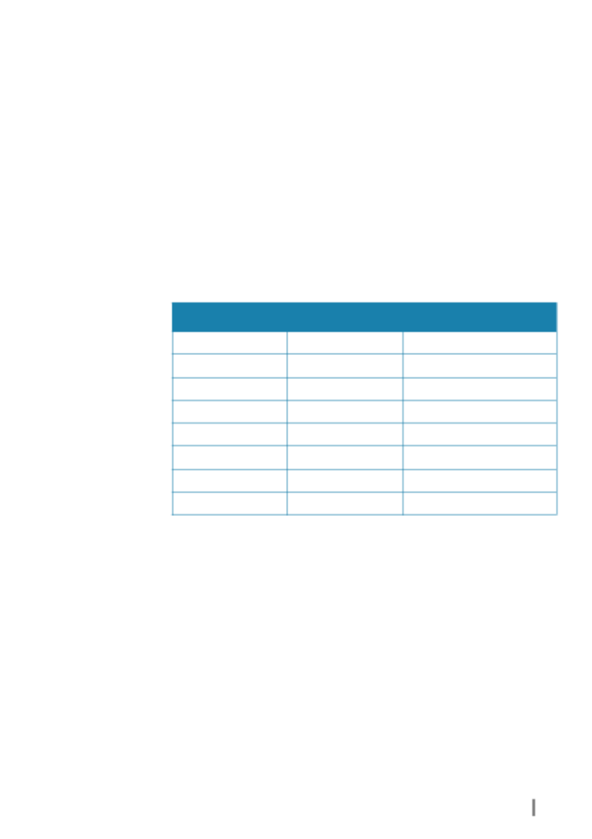
Fishing mode
This feature consists of preset packages of sonar settings designed
for specific fishing conditions.
ÚNote: Selecting the proper fishing mode is critical to optimal
sonar performance. If you completed configuration setup at
initial startup, the proper fishing mode has already been
selected.
Fishing mode Depth Palette
General Use ≤ 1,000 ft White background
Shallow Water ≤ 60 ft White background
Fresh Water ≤ 400 ft White background
Deep Water ≤ 5,000 ft Deep Blue
Slow Trolling ≤ 400 ft White background
Fast Trolling ≤ 400 ft White background
Clear Water ≤ 400 ft White background
Ice Fishing ≤ 400 ft White background
Reset fishing mode
Resets selected fishing mode to default settings, allowing you to
clear settings adjustments made while using a fishing mode.
Log sonar
Select to start and stop recording of Sonar data. For more
information, refer to on page 61."Start recording log data"
This option is also available from the Advanced option in the Sonar
menu.
Sonar | ELITE Ti Operator Manual 67

View Sonar log
Used to view Sonar recordings. The log file is displayed as a paused
image, and you control the scrolling and display from the menu.
You can use the cursor on the image, measure distance, and set
view options as on a live Sonar image. If more than one channel was
recorded in the selected Sonar file, you can select which channel to
display.
You exit the view function by selecting the in the upper rightX
corner.
Installation
Used for installation and setup. See the separate ELITE Ti Installation
manual.
68 Sonar | ELITE Ti Operator Manual

StructureScan
StructureScan HD uses high frequencies to provide a high
resolution, picture-like image of the seabed.
StructureScan HD provides a wide coverage in high detail with
SideScan, while DownScan provides detailed images of structure
and fish directly below your boat. The StructureScan page is
accessed from the page when the TotalScan transducer isHome
connected.
ÚNote: This unit cannot operate CHIRP frequencies and SideScan
at the same time. If you turn on StructureScan Left/Right view,
you will not be able to use the CHIRP sonar.
The StructureScan image
The view
The StructureScan panel can be set up as a DownScan image, or
showing left/right side scanning.
The DownScan image can also be added as an overlay to the
traditional Sonar image.
8
StructureScan | ELITE Ti Operator Manual 69

1Depth
2Temperature
3Bottom
4Frequency
5Zoom (downscan) / Range (sidescan) icons
6Range scale
Zooming the StructureScan image
You can zoom a StructureScan image by:
•using the zoom (+ or -) buttons
•using the / keys+ -
Zoom level is shown on the bottom left side of the panel.
Using the cursor on the StructureScan
panel
By default, the cursor is not shown on the StructureScan image.
When you position the cursor on a DownScan image, the screen
pauses, the cursor information window and the history bar are
activated. On a DownScan image, the depth is shown at cursor
position.
When you position the cursor on a SideScan image, the screen
pauses, and the cursor information window is activated. On a
SideScan image, the left/right distance from the vessel to the cursor
are shown at the cursor position.
To remove the cursor and the cursor elements from the panel,
select the option.Clear cursor
70 StructureScan | ELITE Ti Operator Manual

Viewing StructureScan history
When the cursor is active in a DownScan view, the history bar is
shown at the top of the panel.
In a SideScan view, you can pan the image to see sides and history
by dragging the image left, right, and up.
To resume normal StructureScan scrolling, press .Clear cursor
Setting up the StructureScan image
Use the StructureScan menu to set up the image. When the cursor
is active, some options in the menu are replaced with cursor mode
features. Select to return to the normal menu.Clear cursor
Range
The range setting determines the water depth and SideScan range
that is visible on the screen.
Auto range
When the range is set to Auto the system automatically sets the
range depending on the water depth.
StructureScan | ELITE Ti Operator Manual 71

Preset range levels
You can select between several preset range levels.
StructureScan frequencies
StructureScan supports two frequencies. 455 kHz provides ideal
range and image quality in most situations, while 800kHz is used to
provide higher detail in shallow water.
Contrast
Determines the brightness ratio between light and dark areas of the
screen.
To adjust the contrast setting:
1. Select the contrast icon or activate the contrast option in the
menu to display the color adjustment bar
2. Drag the bar up or down to get the desired contrast setting or
select .Auto contrast
ÚNote: We recommend that you use .Auto contrast
Palettes
You can select between several display palettes optimized for a
variety of fishing conditions.
View
You can set up the StructureScan page as a DownScan image, left
only, right only, or left/right side scanning.
Stop sonar
Use the menu option when you want to turn off theStop sonar
StructureScan transducer, but not turn off the unit.
72 StructureScan | ELITE Ti Operator Manual

Advanced StructureScan settings
Surface clarity
Wave action, boat wakes and temperature inversions can cause on-
screen clutter near the surface.
The surface clarity option reduces surface clutter by decreasing the
sensitivity of the receiver near the surface.
ÚNote: By default, surface clarity is set to Low, for optimal image
return and clarity.
Flipping the Structure image left/right
If required, the left/right SideScanning images can be flipped to
match the direction of the transducer installation.
Range Lines
Range lines can be added to the image to make it easier to estimate
depth (Downscan) and distance (SideScan).
Preview
You can turn off sonar history preview, have it always shown at the
top of the screen, or have it appear only when the cursor is active.
By default, the sonar history preview appears when the cursor is
active.
Recording StructureScan data
You can record StructureScan data and save the file internally in the
unit, or onto a memory card as described in on"Start recording sonar data"
page 61.
StructureScan | ELITE Ti Operator Manual 73

StructureMap
The StructureMap feature overlays SideScan images from a
StructureScan source on the map. This makes it easier to visualize
the underwater environment in relation to your position, and aids in
interpreting SideScan images.
The StructureMap image
The example below shows a chart panel with Structure overlay,
combined with a traditional SideScan panel.
You move around in the chart as usual when you have a Structure
overlay:
•Touch operation: zoom the chart and the scanned image by
using the zoom (+ or -) buttons. Drag on the panel to view the
scanned image.
•Key operation: zoom the chart and the scanned image by using
the / keys.+ -
Selecting the option removes the cursor from theClear cursor
panel, and the chart center is positioned at the vessel.
Activating Structure overlay
1. Turn on Structure overlay from the chart menu
- The chart menu is increased to show Structure options
- Structure data starts to appear on the chart screen as soon as
Structure overlay is enabled
9
74 StructureMap | ELITE Ti Operator Manual

2. Select Structure source
- Live data is default
ÚNote: Structure overlay can also be activated by selecting a
saved StructureMap file in the files browser.
StructureMap sources
Two sources can be used to overlay Structure logs on the charts, but
only one can be viewed at a time:
•Live data - Used when StructureScan data is available on the
system.
•Saved files - These are recorded StructureScan (*.sl2) data that are
converted to StructureMap (*.smf) format. Saved *.smf files can
be used even if no StructureScan sources are connected.
Live source
When live data is selected, the SideScan imaging history is displayed
as a trail behind the vessel icon. The length of this trail varies
depending on available memory in the unit and range settings. As
the memory fills up, the oldest data is automatically deleted as new
data is added. When increasing the search range, the ping speed of
the StructureScan transducer is reduced, but the width and the
length of the image history is increased.
ÚNote: Live mode does not save any data. If the unit is turned off,
all recent data is lost.
Saved files
When Saved files are selected, the StructureMap file is overlaid on
the map based on position information in the file.
If the chart scale is large, the StructureMap area is indicated with a
boundary box until the scale is large enough to show Structure
details.
Saved mode is used to review and examine StructureMap files, and
to position the vessel on specific points of interest on a previous
scanned area.
ÚNote: When saved files are used as the source, all StructureMap
files found on the memory card and in the system’s internal
memory are displayed. If there is more than one StructureMap
of the same area, the images overlap and clutter the chart. If
several logs of the same area are required, the maps should be
put on separate memory cards.
StructureMap | ELITE Ti Operator Manual 75

StructureMap tips
•To get a picture of taller structures (a wreck, etc.) — do not drive
over it, instead, steer the boat so the structure is on the left or
right side of your vessel.
•Do not use Autorange when using StructureScan. Set your
structure range to a significantly greater level (two-to-three
times) than the water depth to ensure a complete scan and to
maximize conversion accuracy.
•Do not overlap history trails when conducting a side-by-side scan
of an area.
Recording StructureScan data
StructureScan data can be recorded from a chart panel with
Structure overlay enabled.
StructureScan recordings can also be started from a StructureScan
panel.
When StructureScan data is being recorded, there is a flashing red
symbol and a message appears periodically at the bottom of the
screen.
ÚNote: The message includes information about file size. Keep
the size of your logs to 100MB or less to allow for faster file
conversion.
The recording is stopped by re-selecting the record function.
Converting StructureScan data to StructureMap format
A StructureScan log file (.sl2) is converted to StructureMap format
(.smf ) after recording from the recording dialog, or from the files
browser.
76 StructureMap | ELITE Ti Operator Manual

You can create standard or high resolution files. High resolution .smf
files capture more detail, but take longer to convert and are larger
than standard resolution files.
To save disc space it is recommended to remove the StructureScan
(.sl2) files after conversion.
Using StructureMap with mapping cards
StructureMap allows you to maintain full chart capability and can be
used with embedded cartography as well as Navionics, Insight and
other third-party charting cards compatible with the system.
When using StructureMap with mapping cards, copy the
StructureMap (.smf ) files to the unit’s internal memory. We
recommend keeping copies of StructureMap files on external
mapping cards.
StructureMap | ELITE Ti Operator Manual 77

Structure options
You adjust the StructureMap settings from the Structure options
menu. The menu is available when Structure overlay is enabled.
Not all options are available when saved StructureMap files are used
as the source. Unavailable options are greyed.
Range
Sets the search range.
Transparency
Sets the opaqueness of the Structure overlay. With minimum
transparency settings, the chart details are almost hidden by the
StructureMap overlay.
Palette
Selects Structure palette.
Contrast
Determines the brightness ratio between light and dark areas of the
screen.
Water column
Shows/hides the water column in Live mode.
If turned OFF schools of bait fish might not be seen on the SideScan
image.
If turned ON the accuracy of the SideScan image on the map might
be affected by the water depth.
Frequency
Sets the transducer frequency used by the unit. 800 kHz offers the
best resolution, while 455 kHz has greater depth and range
coverage.
Clear live history
Clears existing live history data from the screen and begins showing
only the most current data.
78 StructureMap | ELITE Ti Operator Manual

Log Sonar data
Records StructureScan data.
Source
Selects StructureMap source.
StructureMap | ELITE Ti Operator Manual 79

Info panels
The panels consist of multiple gauges - analog, digital, and barInfo
- that can be customized to display selected data. The panel
displays data on dashboards, and you can define up to ten
dashboards within the panel.
Dashboards
A set of dashboard styles are predefined to display vessel,
navigation, and angler information.
ÚNote: Only the Navigation dashboard is available on the
Elite-5Ti.
You switch between the panel’s dashboards by selecting the left
and right arrow buttons on the panel. You can also select the
dashboard from the menu.
Vessel dashboard Navigation dashboard Angler dashboard
ÚNote: Additional dashboards can be activated from the menu if
other systems are present on the network.
Customizing the Info panel
You can customize the Info panel by changing the data for each of
the gauges in the dashboard, by changing the dashboard layout,
and by adding new dashboards. You can also set limits for analog
gauges.
All edit options are available from the Info panel menu.
Available editing options depend on which data sources are
connected to your system.
10
80 Info panels | ELITE Ti Operator Manual

Edit a dashboard
Activate the dashboard you want to edit, then:
1. Activate the menu
2. Select the edit option
3. Select the gauge you want to change. Selected gauge is
indicated with a colored background
4. Select information to be displayed, configure limits, and
eventually change the source for the information
5. Save your changes by selecting the save option in the menu
Info panels | ELITE Ti Operator Manual 81

Trolling motor autopilot
If a MotorGuide Xi5 trolling motor with Pinpoint GPS is connected
to the NMEA 2000 network, then the SmartSteer (autopilot)
functionality is available on all units except the ELITE-5Ti.
To use trolling motor autopilot functionality, you need the
following:
•MotorGuide Xi5 trolling motor with Pinpoint GPS (available from
MotorGuide)
•MotorGuide Pinpoint GPS Gateway (available from MotorGuide)
•NMEA 2000 network
Connect the MotorGuide Pinpoint GPS Gateway to your NMEA
2000. For details about installing this equipment, refer to the
separate installation manuals that come with the equipment.
The Autopilot can automatically control the trolling motor to:
•Maintain a set heading
•Maintain the vessel's position
•Navigate to the cursor position, to a waypoint, or along a route
•Follow pre-defined turn patterns
•Control the speed of the trolling motor
ÚNote: An autopilot is a useful navigational aid, but DOES NOT
replace a human navigator.
Xi5 trolling motor software
If at any time there is an update required for your Xi5 trolling motor,
instructions will be made available by MotorGuide, and posted on
lowrance.com.
Follow the onscreen instructions to update Xi5 software.
Safe operation with the autopilot
Warning: An autopilot is a useful navigational aid,
but DOES NOT replace a human navigator.
11
82 Trolling motor autopilot | ELITE Ti Operator Manual
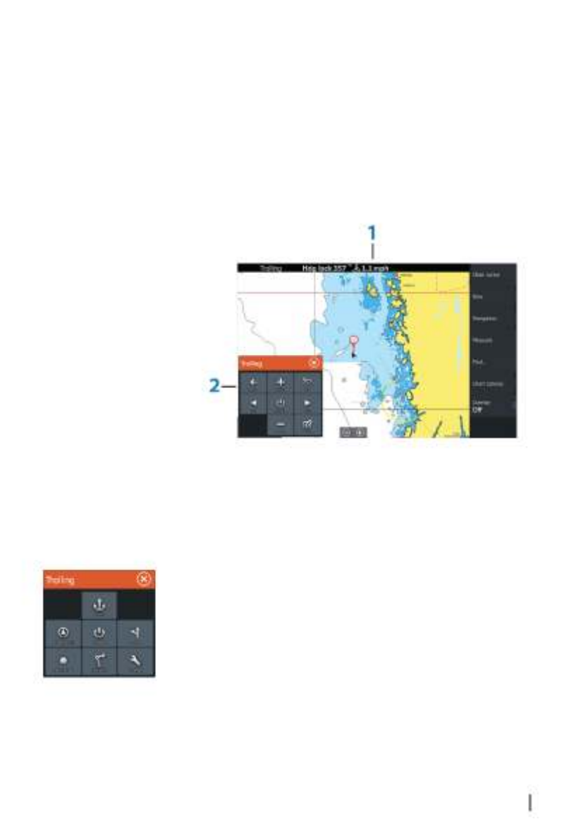
Switching from automatic navigation to
standby mode
To switch from autopilot to handheld remote or foot pedal steering,
set the autopilot to standby mode. You can select standby mode
from the or the dialog.Autopilot Controller System Controls
Autopilot interface
1Autopilot information bar
2Autopilot Controller
The Autopilot Controller
The autopilot is controlled from the ,Autopilot Controller
activated from the dialog displayed by pressingSystem Controls
the key.Power
You can select the position of the Autopilot Controller on the page.
Refer to on page 88."Autopilot settings"
ÚNote: As long as the is active, youAutopilot Controller
cannot operate the background panel or its menu.
The can also be set up as a panel in a splitAutopilot Controller
panel page by using the Page Editor to make a Favorite page. For
Trolling motor autopilot | ELITE Ti Operator Manual 83

information about Favorite pages, refer to on"Adding new favorite pages"
page 26.
The Autopilot information bar
The is displayed when an autopilotAutopilot information bar
mode is selected. The bar includes information about the autopilot
mode and navigational information. The bar is present on all pages
if the autopilot is in an active mode. In the Autopilot settings dialog,
you can select that the bar is off when the autopilot is in standby
mode. Refer to on page 88."Autopilot settings"
Autopilot control of the trolling motor
Selecting an Arrival mode
The autopilot switches from navigation mode to the selected arrival
mode when your vessel reaches the destination. Arrival mode is set
to Standby by default. Before starting a navigation mode or a turn
pattern, it is important to select an arrival mode that fits your
navigation needs. Refer to on page 88."Arrival mode"
Anchor mode
Maintains your vessel position at a selected location.
ÚNote: When in anchor mode, your vessel orientation can be
affected by wind or currents.
The following occurs when you select to anchor at:
•Waypoint
Enables anchor mode when your vessel arrives at a selected
waypoint.
•Cursor
Enables anchor mode when your vessel arrives at the cursor
position.
•Here
Enables anchor mode at your current location.
84 Trolling motor autopilot | ELITE Ti Operator Manual

Heading Lock mode
Locks and maintains the current vessel heading. Use the left and
right arrow buttons in the to make headingAutopilot Controller
adjustments. To make small heading adjustments, single-select the
left or right buttons. For larger adjustments, select and hold the left
or right buttons.
Standby mode
Cancels autopilot activity and returns the vessel to handheld remote
or foot pedal steering control.
Turn pattern steering
Steers the vessel in predefined turn patterns. When you select a turn
pattern, the system creates temporary waypoints on the turn. The
last waypoint on the turn is the final waypoint. When the vessel
reaches the final waypoint, the vessel goes into arrival mode. Refer
to on page 88."Arrival mode"
Setting up a turn pattern
1. Select a turn pattern.
2. Enter the desired value(s) in the turn pattern dialog or use
default settings.
3. Select the direction of the turn.
ÚNote: Selecting a turn radius smaller than the GPS accuracy
may result in incomplete navigation of the turn pattern.
U-turn
Changes the current set heading to be 180° in the opposite
direction.
C-turn
Steers the vessel in a C-shaped pattern.
Spiral turn
Steers the vessel in a spiral with a decreasing or increasing radius.
Negative values indicate decreasing radius while positive values
indicate increasing radius.
Trolling motor autopilot | ELITE Ti Operator Manual 85
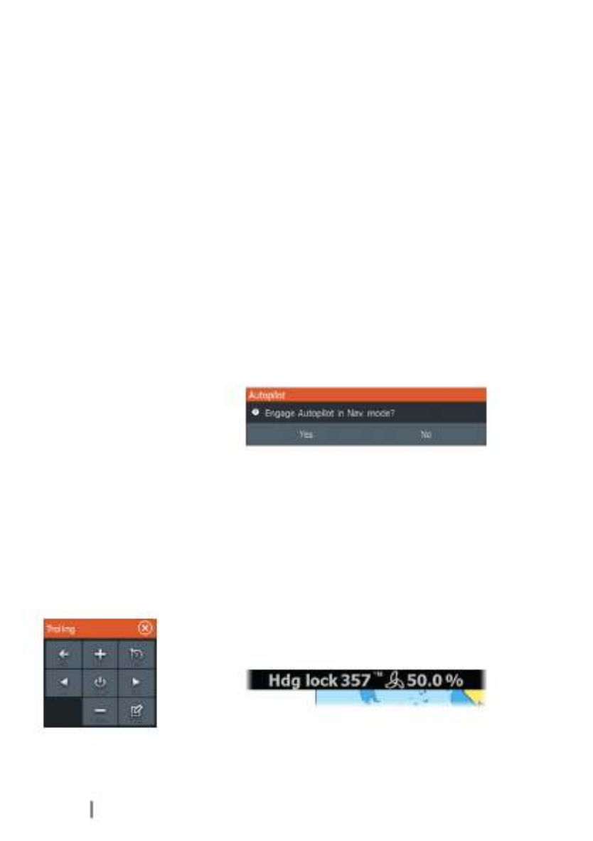
Zigzag turns
Steers the vessel in a zigzag pattern.
Square turn
Makes the vessel automatically turn 90° after having travelled a
defined leg distance.
Lazy S-turn
Makes the vessel yaw around the main heading.
Navigation mode
In Nav. mode you can use the autopilot to steer the boat to cursor
position, to a waypoint position, or along a pre-defined route. The
position information from the GPS is used to keep the boat on the
track line towards the destination point.
When you start navigating from an application (chart, steering, etc)
you are prompted to engage the autopilot in Nav. mode.
You can also initiate Nav. mode from the Autopilot Controller
after navigation is started.
When you reach the destination, the autopilot switches to your
Arrival mode setting. Refer to on page 88."Autopilot settings"
Trolling motor speed control
In navigation modes (Heading lock mode, Nav. mode, and Turn
pattern steering) there are two ways to control speed:
•Prop - selects a target propeller rate (percentage of power)
shown as in the Autopilot information bar.%
86 Trolling motor autopilot | ELITE Ti Operator Manual

•Cruise - selects a target cruise control speed shown as , ,mph kn
or in the Autopilot information bar.kph
ÚNote: Cruise set speed sets the target speed for your vessel.
Your vessel may not be able to achieve the set target. The
Cruise set speed (not your current speed) is displayed in the
Autopilot information bar.
Speed adjustments
You can make speed adjustments on the Heading lock and
Navigation control dialogs by selecting the Spd up (+) and Spd
down (-) buttons, or by selecting the or optionSet Spd Set prop
and entering your desired speed or propeller rate.
Recording and converting a trail to a route
The button is used to record and convert a trail or partRecord trail
of a trail to a route.
1. Select at the desired location to start recording aRecord trail
new trail.
2. Select to select the end location of the route. TheSave route
Edit trail dialog appears.
3. Select . The Edit route dialog appears.Create route
4. Enter the route details and save it.
Trolling motor autopilot | ELITE Ti Operator Manual 87

Autopilot settings
Autopilot settings is applicable for all units except ELITE-5Ti.
Chart compass
You can select to show a compass symbol around your boat on the
chart panel. The compass symbol is off when the cursor is active on
the panel.
Autopilot control location
Controls the location of the on the panel.Autopilot controller
Auto hide autopilot bar
Controls whether the Autopilot information bar is shown when the
autopilot is in Standby mode.
Arrival mode
The trolling motor autopilot switches from navigation mode to the
selected arrival mode when your vessel reaches the destination.
ÚNote: Before starting a navigation mode or a turn pattern, it is
important to select an arrival mode that fits your navigation
needs.
Arrival modes are:
88 Trolling motor autopilot | ELITE Ti Operator Manual
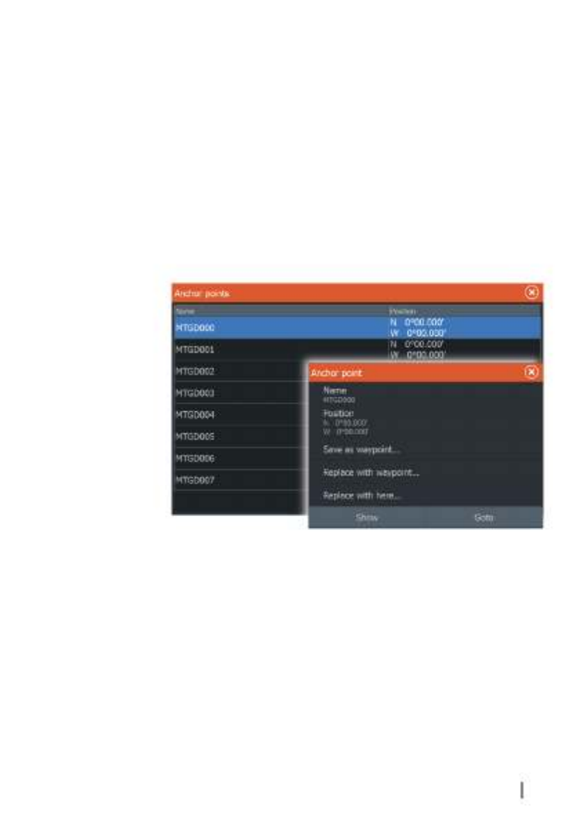
•Standby
Cancels autopilot activity and returns the vessel to handheld
remote or foot pedal control.
•Heading lock
Locks and maintains the last vessel heading.
•Anchor
Anchors the vessel at the current destination.
ÚNote: We recommend only using heading lock in open water.
Anchor point setup
Anchor points can be saved as a new waypoint, replaced with an
existing waypoint, or set as your current coordinates.
Anchor points are synced with the Xi5 trolling motor. If any anchor
points are stored in the motor, they appear in the anchor points list.
Trolling motor autopilot | ELITE Ti Operator Manual 89

Wireless connection
GoFree wireless connectivity gives you the ability to:
•Use a wireless device to remotely view (smartphone and tablet)
and control the system (tablet only).
•Access the GoFree Shop.
•Upload your Sonar logs to create custom maps at Insight
Genesis.
•Download software updates
•Connect to third party applications
ÚNote: Maps, charts, software updates, and other data files can
be large. Your data provider may charge you based on the
amount of data you transfer. If you are unsure contact the
service provider for information.
The unit includes:
•Built-in wireless functionality for connecting to the internet and
wireless devices such as smartphones and tablets.
•Built-in Bluetooth wireless technology.
The built-in Bluetooth wireless technology gives you the ability
to connect the unit to Bluetooth enabled devices. For more
information, refer to on page 93."Bluetooth wireless technology"
Connect and disconnect from a wireless
hotspot
To connect to a wireless hotspot, select the Wireless option in the
System Controls dialog and then select Not Connected. This opens
the Wireless Devices dialog. Use this dialog to select the desired
hotspot, enter the login information and then select Connect.
Connecting to a wireless hotspot changes the wireless mode to
Client mode. In this mode, you can access the GoFree Shop.
To disconnect from a wireless hotspot, select the Wireless option in
the System Controls dialog, then select Connected , andhotspot_name
then Disconnect. This changes the wireless mode to Access point
mode. In this mode, you can connect a wireless device so that Apps
12
90 Wireless connection | ELITE Ti Operator Manual
such as GoFree Controller & Viewer can access the vessel's
navigation information.
GoFree Shop
The built-in wireless functionality must be connected to an external
wireless hotspot in order to access the GoFree Shop.
At the GoFree Shop you can browse, purchase and download
compatible content for your system including navigation charts and
Insight Genesis Maps. When you log on, the system automatically
gives you a notification if a new software version is available for your
system. If an update is available, you can download it to a card slot
or defer the download until later. If you defer the download until
later, the notification is available in the About dialog accessible from
the System Settings.
GoFree Controller & Viewer
The wireless functionality lets you use a wireless device to remotely
view (smartphone and tablet) and control the system (tablet only).
The system is viewed and controlled from the wireless device by the
GoFree Controller & Viewer Apps downloaded from their relevant
Application store. When remote control is accepted, the active page
is mirrored to the wireless device.
ÚNote: To use smartphones and tablets to view and control the
system, wireless functionality must be disconnected from the
wireless hotspot (in ).Access point mode
ÚNote: For safety reasons, Autopilot and CZone functions cannot
be controlled from a wireless device.
Connecting a tablet
Install the GoFree App on the tablet before following this
procedure.
1. Set the internal wireless to mode. To do this,Access Point
select the page in the Wireless settingsWireless devices
dialog and then select the Internal wireless. Next, select the
Mode Internal Access Point option and then select .
2. Select the Internal Wireless device on the Wireless devices
page to view its Network key.
3. Navigate to the wireless network connection page on the tablet,
and find the unit or GoFree wireless network. If more thanxxxx
Wireless connection | ELITE Ti Operator Manual 91
Especificaciones del producto
| Marca: | Lowrance |
| Categoría: | navegador |
| Modelo: | Elite Ti |
¿Necesitas ayuda?
Si necesitas ayuda con Lowrance Elite Ti haz una pregunta a continuación y otros usuarios te responderán
navegador Lowrance Manuales

18 Septiembre 2024
18 Septiembre 2024
2 Septiembre 2024
26 Agosto 2024
26 Agosto 2024
22 Agosto 2024
16 Agosto 2024
15 Agosto 2024
14 Agosto 2024
13 Agosto 2024
navegador Manuales
- navegador Sony
- navegador Philips
- navegador Garmin
- navegador JVC
- navegador Kenwood
- navegador Motorola
- navegador Medion
- navegador Nokia
- navegador Pioneer
- navegador Acer
- navegador Alfa Romeo
- navegador Alpine
- navegador Airis
- navegador Silvercrest
- navegador Thomson
- navegador Pyle
- navegador Asus
- navegador Caliber
- navegador Bushnell
- navegador Overmax
- navegador Blaupunkt
- navegador Harman Kardon
- navegador Humminbird
- navegador Skoda
- navegador BMW
- navegador Sanyo
- navegador Parrot
- navegador Midland
- navegador Sylvania
- navegador Marquant
- navegador Toyota
- navegador Binatone
- navegador Volkswagen
- navegador Magellan
- navegador Chrysler
- navegador Clarion
- navegador Mio
- navegador Uniden
- navegador Audiovox
- navegador Insignia
- navegador Goclever
- navegador Dual
- navegador Navigon
- navegador Boss
- navegador Cobra
- navegador Honda
- navegador Eagle
- navegador TomTom
- navegador Navitel
- navegador Navman
- navegador Lanzar
- navegador Simrad
- navegador Jensen
- navegador Zenec
- navegador Furuno
- navegador Scosche
- navegador Coyote Systems
- navegador Rand McNally
- navegador VDO
- navegador Soundstream
- navegador VDO Dayton
- navegador Becker
- navegador Igo
- navegador Kalkhoff
- navegador Route 66
- navegador Falk
- navegador Seecode
- navegador Nav N Go
- navegador Sygic
- navegador Raymarine
- navegador Pharos
- navegador Viamichelin
- navegador Xzent
- navegador ModeCom
- navegador CarTrek
- navegador V7
- navegador Whistler
- navegador Dynavin
- navegador Cheetah
- navegador Cydle
- navegador ESX
- navegador Lark
- navegador LXNAV
- navegador Planet Audio
- navegador Eclipse
- navegador Voice Caddie
- navegador SkyCaddie
- navegador TELE System
- navegador IZZO Golf
- navegador Zoleo
- navegador Dashmate
- navegador GlobalSat
Últimos navegador Manuales
19 Octubre 2024
14 Octubre 2024
14 Octubre 2024
14 Octubre 2024
12 Octubre 2024
12 Octubre 2024
12 Octubre 2024
10 Octubre 2024
9 Octubre 2024
9 Octubre 2024