Max SFX Series Manual de Usario
Max
receptor de satélite
SFX Series
Lee a continuación 📖 el manual en español para Max SFX Series (133 páginas) en la categoría receptor de satélite. Esta guía fue útil para 19 personas y fue valorada con 4.5 estrellas en promedio por 2 usuarios
Página 1/133

User’s Guide
SFX Series Satellite Receiver

All rights are reserved by International Datacasting Corporation. This User’s Guide contains the valuable properties and trade secrets
of International Datacasting Corporation, embodying substantial creative efforts and confidential information, ideas or expressions. No
part of this User’s Guide may be reproduced, translated or transmitted in any form or by any means without the prior written permission
of this company.
The information in this document is subject to change in order to improve reliability, design or function without prior notice; all changes
are incorporated into new editions and/or revisions.
In no event will we be liable for technical or editorial errors or omissions contained herein; nor for incidental, special or consequential
damages from the furnishing, performance or use of this manual.
NOTE: The screen captures shown in this Guide are for reference only and may not exactly match the pages that are displayed on
your browser. Not all receiver models and/or versions of the application firmware will support all features described in this guide. If you
have any questions regarding availability of certain features, please contact International Datacasting’s Customer Service Department
(see Chapter 3).
Nota: Las pantallas mostradas en esta Guía deben ser tomadas solo como referencia, ya que pueden no coincidir exactamente con
las pantallas mostradas en su navegador. No todos los modelos de receptores y/o versiones de “firmware” incluyen todas las
funciones descritas en esta guía. Si usted tiene alguna pregunta con respecto a la disponibilidad de alguna de estas funciones, por
favor contacte al Departamento de Servicio al Cliente de International Datacasting (Ver Capitulo 3).
SFX Series Satellite Receiver User’s Guide
International Datacasting Corporation Part No. 92080190-50 /DA755
Note: International Datacasting Corporation has produced a separate Addendum to this manual for the Pro Audio and Pro Video
series SuperFlex satellite receivers. Please proceed to Chapter 3 for more information on obtaining these Addenda.
Nota: Esta disponible por parte de International Datacasting un apéndice a este manual con información especifica para los receptores
satelitales Pro Audio y Pro Video de la serie SuperFlex. Por favor vea el capitulo 3 para mayor información de cómo obtener este
apéndice.
Record of Revisions
International Datacasting Corporation is constantly improving its products and therefore the information in this document is subject to
change without prior notice. International Datacasting makes no warranty of any kind with regard to this material, including but not
limited to the implied warranties of merchantability and fitness for a particular purpose.
No responsibility for any errors or omissions that may pertain to the material herein is assumed. International Datacasting makes no
commitment to update or to keep current the information contained in this document. International Datacasting assumes no
responsibility for use of any circuitry other than the circuitry employed in International Datacasting’s systems and equipment.
Copyright © 2007, Rev.2.2, incorporating DA 755 International Datacasting Corporation
All rights reserved. Printed in Canada.
LINUX is a registered trademark of Linus Torvalds, in the United States and other countries.
Microsoft, Windows and Windows NT are registered trademarks of Microsoft Corporation in the United States and/or other countries.
Preface

SFX SERIES USER’S GUIDE
Rev 2.2 1
Chapter 1 - Getting Started ................................................................................................................4
General...............................................................................................................................................4
What You Should Have Received......................................................................................................4
Front Panel.........................................................................................................................................5
Rear Panel .........................................................................................................................................6
Equipment Installation........................................................................................................................9
Power up procedure...........................................................................................................................9
Status and Control of the Satellite Receiver....................................................................................10
Controlling the Receiver with the Front Panel LCD Display/Keypad Interface................................10
Using the LCD/Keypad Interface to change the IP of the receiver for communication
with the Web GUI Interface...........................................................................................................14
Using the LCD/Keypad Interface to Setup the Carrier Parameters of Your Receiver..................14
Controlling the Receiver with the Terminal Interface.......................................................................15
Controlling the Receiver with the Web GUI .....................................................................................16
Controlling the Receiver with SNMP................................................................................................19
Controlling the Receiver with NetManager2 ....................................................................................20
Chapter 2 - Web GUI Operation.......................................................................................................21
Main Menu Page..............................................................................................................................21
Logout Icon....................................................................................................................................21
IDC Logo.......................................................................................................................................21
Receiver Identity............................................................................................................................21
Main Menu Tool Bar Area .............................................................................................................22
Main Display Area.........................................................................................................................22
Metrics Display Area .....................................................................................................................22
Main Menu Tool Bar.........................................................................................................................23
The Action of the Mouse..................................................................................................................27
Common Menu Items.......................................................................................................................27
Drop-down Selection Boxes.............................................................................................................27
Identity..............................................................................................................................................28
DVB Carrier......................................................................................................................................30
DVB Carrier Definitions.................................................................................................................30
LNB Attributes...............................................................................................................................32
(The LNB Offset) ........................................................................................................................32
Channel Guide .................................................................................................................................34
Data Delivery....................................................................................................................................36
PIDs and Ports..............................................................................................................................38
(PID Filtering and PID Types) ....................................................................................................38
Table of Contents

SFX SERIES USER’S GUIDE
Rev 2.2 2
IGMP .............................................................................................................................................44
Static Routing................................................................................................................................46
Multicast Routing...........................................................................................................................49
Source NAT...................................................................................................................................54
Destination NAT............................................................................................................................56
Filtering..........................................................................................................................................59
Firewall..........................................................................................................................................62
TTL Translation.............................................................................................................................66
XD ....................................................................................................................................................68
XD Client Overview....................................................................................................................68
Windows File Sharing....................................................................................................................69
XD Client.......................................................................................................................................70
XD DataMan..................................................................................................................................72
XD License Info.............................................................................................................................73
XD Retriever..................................................................................................................................73
Logging.............................................................................................................................................75
Metrics..............................................................................................................................................78
Filtering Metrics.............................................................................................................................79
Interface Metrics............................................................................................................................80
MRTG Metrics...............................................................................................................................81
Multicast Routing Metrics..............................................................................................................82
RF & PID Metrics...........................................................................................................................83
System Health Metrics ..................................................................................................................85
Configuration....................................................................................................................................85
Apache ..........................................................................................................................................86
Channel Guide Configuration........................................................................................................87
DHCP Server.................................................................................................................................87
Date and Time...............................................................................................................................88
Ethernet Configuration ..................................................................................................................89
FTP................................................................................................................................................91
GUI Configuration..........................................................................................................................92
NCC Configuration........................................................................................................................93
Password Manager .......................................................................................................................94
SFX Home Page ...........................................................................................................................94
SSH...............................................................................................................................................95
Samba...........................................................................................................................................96
Volume ..........................................................................................................................................98
Utilities..............................................................................................................................................98
Documentation..............................................................................................................................98
Irdeto .............................................................................................................................................98
Backup and Restore......................................................................................................................98
Ping Utility .....................................................................................................................................99
Restart Receiver..........................................................................................................................100
TCP/UDP Port Registry...............................................................................................................101
Traceroute Utility.........................................................................................................................102
Upgrade..........................................................................................................................................102
Chapter 3 - Service and Contact Information...............................................................................104
Troubleshooting..............................................................................................................................104
Preventative Maintenance...........................................................................................................104
Troubleshooting Procedures.......................................................................................................104
Contacting Your Supplier ............................................................................................................105
Shipping & Packaging.................................................................................................................105

SFX SERIES USER’S GUIDE
Rev 2.2 3
Warranty & Service ........................................................................................................................105
Warranty Period ..........................................................................................................................106
Warranty Coverage Limitations...................................................................................................106
Warranty Replacement & Adjustment.........................................................................................106
Liability Limitations......................................................................................................................106
Warranty Repair Return Procedure.............................................................................................107
Non-Warranty Repair ..................................................................................................................107
Contacting IDC for More Information.............................................................................................107
Important EMI & Safety Certification Information...........................................................................108
Receiver Installation....................................................................................................................108
Exterior Equipment Installation ...................................................................................................108
Operating & Cleaning..................................................................................................................109
Service ........................................................................................................................................109
EMI/EMC Certification.................................................................................................................109
Appendix A - Receiver Configurations.........................................................................................111
Appendix B - Irdeto Decryption Option ........................................................................................112
Pre-installation Procedure..............................................................................................................112
Inserting the Irdeto Smart Card......................................................................................................112
Web GUI Operation........................................................................................................................113
Front Panel LED Indications ..........................................................................................................115
Appendix C - Redundancy Option.................................................................................................116
N to M Redundancy .......................................................................................................................117
Web GUI Operation........................................................................................................................118
Front Panel LED Indications ..........................................................................................................120
Appendix D - DVB Conditional Access System (CAS) Option...................................................121
Pre-installation Procedure..............................................................................................................121
Inserting the CA Module.................................................................................................................121
Web GUI Operation........................................................................................................................123
Front Panel LED Indications ..........................................................................................................125
Appendix E - FlexKey Option.........................................................................................................126
Web GUI Operation........................................................................................................................126
Front Panel LED Indications ..........................................................................................................128
Appendix F - ASI Option.................................................................................................................129
Web GUI Operation........................................................................................................................129

SFX SERIES USER’S GUIDE
Rev 2.2 4
Getting Started
General
International Datacasting Corporation (IDC) would like to thank you for purchasing your SFX Series SuperFlex
Satellite Receiver (herein referred to as the “satellite receiver”). This User’s Guide provides the essential
information required to get started with installation and basic operation of your satellite receiver. The intent of
this guide is to give you enough information so that you can power up the unit and perform enough
operations to communicate with it using the Front Panel or Web GUI. With these interfaces, you can
configure the receiver to lock to a RF carrier, and perform normal operations for your network. You will also
be able to access this User’s Guide on the hard drive, from the Web GUI (via LAN connection).
This chapter provides information to familiarize you with the satellite receiver, as it comes out of the box. This
information can be used to step through a preliminary investigation of the unit you have received, as well as initially
applying power to ensure that it is operating correctly and has not been damaged during transit.
The illustrations that are provided in this chapter identify indicators and connectors on the satellite receiver, in the rack
mount configuration. Acquaint yourself with these parts as illustrated, and refer to the physical unit itself. Throughout
the remainder of this Guide, reference will be made to these parts.
Once installed and powered, varying levels of Status and Control for configuration of the satellite receiver will be
available through one of the following: locally using the Front Panel LCD Display/Keypad, remotely using the Terminal
Interface over SSH or via the RS-232 port, remotely using the Web based Graphical User Interface (GUI), remotely
using SNMP, or remotely using IDC’s NetManager2. This Guide will describe the essential functions for setting up the
satellite receiver so that you can begin communicating and configuring the unit.
What You Should Have Received
You should have received the following package:
• One (1) SFX series satellite receiver,
• One (1) power cord, suitable for use in your country;
• One (1) copy of this User’s Guide (optional) – also available online from the IDC customer service FTP site -
see Chapter 3 for contact information.
It is highly recommended that you retain one set of box and foam packaging that came with the unit, in the rare event
that it has to be shipped back for repair.
Chapter 1
SFX SERIES USER’S GUIDE
Rev 2.2 5
Front Panel
Once you have removed the satellite receiver from the box, please familiarize yourself with the front panel. Refer to
Figure 1- 1 for the location of the indicators. These are the same for both models of receiver - the SXF310x and the
SFX210x, and are described in the table under the figure.
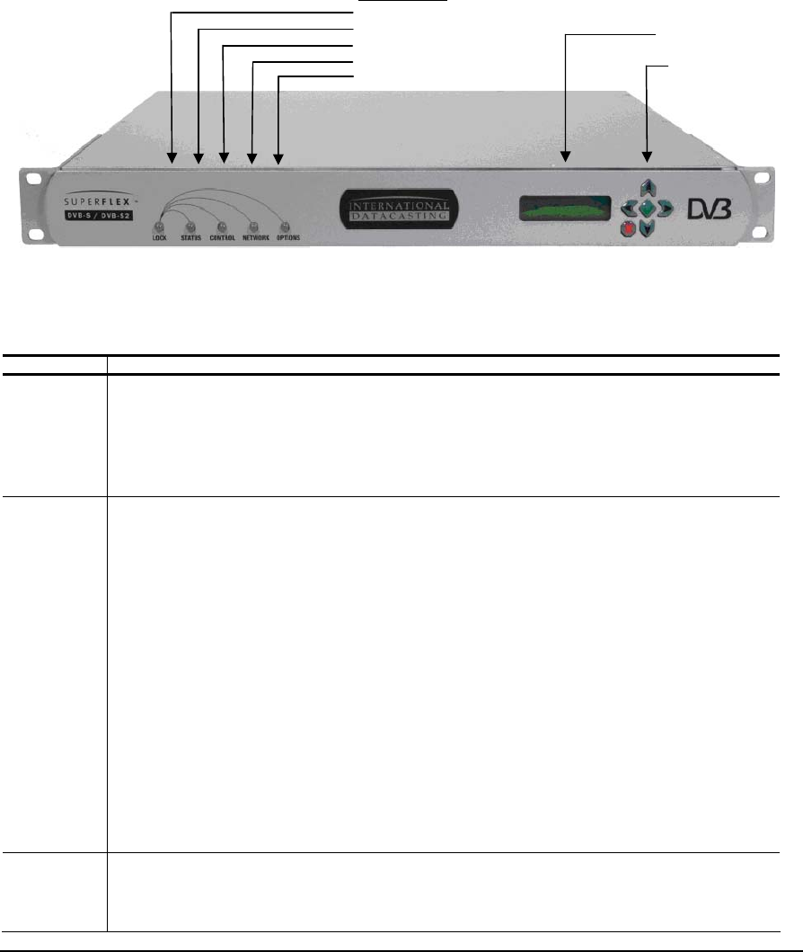
Figure 1- 1 Front Panel Indicators
Indicator Description
LOCK Indicates receiver lock to incoming satellite DVB carrier on the L-Band input.
Off – no power and no lock.
Solid Green – unit is locked to the DVB carrier.
Solid Red – the unit is not locked to the DVB carrier.
STATUS Indicates various power-up states of the receiver, including LNB DC power status to the L-Band
connector.
Off – no power is applied to the receiver.
Solid Green – normal operation and one of:
1. the LNB is powered by the receiver; current drawn is between 50 and 500 mA; or
2. the receiver has not been configured to power the LNB.
Solid Orange – power is being supplied to the LNB, and it is under current (power drawn is <50 mA,
which may possibly indicate an open circuit).
Solid Red – boot and normal operation, can be one of:
1. during the boot, start-up and initialization of the receiver application firmware, remains red
until startup is completed, then turns solid green, orange, or remains red, depending on LNB
status; and
2. during operation, power is being supplied to the LNB and it is over current (power drawn is
>500 mA, which may possibly indicate a short circuit).
CONTROL Indicates the authorization for the receiver to process control commands from the Network Control
Channel (NetManager2 NCC PID stream for the DVB Carrier):
Solid Green – NCC PID is assigned, and the receiver is locked.
LED Indicators
Lock
Status
Control
N
etwor
k
Options
LCD Display
Keypad
SFX SERIES USER’S GUIDE
Rev 2.2 6
Indicator Description
Flashing Off/Green – there is data activity on the NCC PID (i.e. receiving NetManager2 commands).
Orange/Flashing Orange – receiver is in backup state.
Off – NCC PID is not assigned, or the receiver is out of lock and there is no NCC PID.
NETWORK Indicates the authorization and data activity on the satellite network interface.
Solid Green – satellite network interface is authorized (enabled), but there is no data activity.
Flashing Off/Green – satellite network interface is authorized and there is data activity.
Flashing Off/Orange – if the Flexkey decryption, or DVB CAS option is installed, satellite network
interface is authorized and there is data activity, but the data is not being decrypted.
Off – satellite network interface is not authorized.
OPTIONS Indicates status of decryption options installed in the receiver, as applicable. Off indicates that no
options are installed.
Rear Panel
Please refer to Figure 1- 2 below, for the SFX 310x and Figure 1- 3 for the SFX210x rear panel and the table following
for a brief description of each connector on the rear panel.
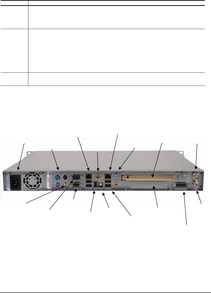
Figure 1- 2 SFX 310x Rear Panel Connectors
PCI slot
(optional)
Universal
AC Power DVB-ASI Port
(optional)
10/100 BaseT
Ethernet Port
Sync Port
(RS-422)
L-Band
Input
from LNB
Multiple USB
ports
(future
expansion)
TV Video Ports
(SFX)
(S-Video,
Composite)
Keyboard (K) &
Mouse (M) Port
SVGA Video
Port (Monitor)
Terminal
Interface Port
(RS-232)
Optional Conditional
Access: CAM or
SmartCard
IEEE 1394
Interface
(future
expansion)
Audio Ports
(SFX)
(Line In,
Line Out,
Mic)
S/PDIF
Interface
(SFX)
Power On
Button
10/100/1000 BaseT
Ethernet Port

SFX SERIES USER’S GUIDE
Rev 2.2 7
Figure 1- 3 SFX 210x Rear Panel connectors
Connector Description
Universal AC Power The Alternating Current (AC) inlet is the main power disconnect. The power cord
connector is used to provide AC power to the satellite receiver. The power
requirements for this equipment are quite flexible, with an acceptable voltage range of
100 to 240 VAC at 50 or 60 Hz.
K (Keyboard) & M
(Mouse) Ports These are standard PS/2 type keyboard and mouse connectors, used when keyboard
and mouse are required for the console.
S-VIDEO & TV Ports These connectors provide baseband composite PAL or NTSC video output and audio
for TV applications (SFX3100 series only).
TERMINAL Interface Port This is a 9-pin RS-232 (DTE) DE-9P (male) connector. It is used as a bi-directional
low speed asynchronous data port for the Terminal Interface at 9600 baud. The
pinouts for this port are as follows:
PIN Acronym Reference
1 DCD Data Carrier Detect
2 RD Receive Data
3 TD Transmit Data
4 DTR Data Terminal Ready
5 GND Ground
6 DSR Data Set Ready
7 RTS Request To Send
8 CTS Clear To Send
9 RI Ring Indicator
VIDEO SVGA Port A standard SVGA output, used when a monitor is required for the console.
USBx Ports (4) These are bi-directional USB 2.0 ports, available for future applications.
Universal
AC Power
DVB-ASI Port
(optional)
10/100 BaseT
Ethernet Port
L-Band
Input
from LNB
Keyboard (K) &
Mouse (M) Port
SVGA video Port
(Monitor)
TV Port
Composite
10/100/1000
BaseT
Ethernet Port
Multiple USB
ports
(future
expansion)
PCI slot
(optional)
Power On
Button
Sync Port
RS-422
Optional Conditional
Access: CAM or
SmartCard
Terminal
Interface Port
(RS-232)

SFX SERIES USER’S GUIDE
Rev 2.2 8
Connector Description
POWER ON Button This button is provided for emergencies only, in the event the motherboard in the
receiver needs to be power cycled. Normally, the receiver automatically starts up
without having to touch this power button. Generally, the button needs to be pressed
briefly to turn the unit on, and held for up to 4 seconds to turn the unit off.
(IEEE) 1394 Interface This interface is not used on the SFX3101, but is available for future use.
AUDIO Ports (LI, LO,
MIC, SPDIF) These are standard unbalanced audio ports: Line Input (LI), Line Output (LO) and
Microphone input (MIC), as provided by the internal AC97 compliant codec. A SPDIF
digital interface is also provided.
PCI Option Slot One PCI option slot is provided for optional PCI cards.
L-BAND This is a 75 ohm, F-type connector that permits connection to the LNB and antenna.
An RG-6 or similar cable of less than 200 feet is recommended. High quality cabling
may be used to provide additional shielding, lower loss or protection from harsh
environments. Direct Current (DC) power is provided to the LNB at either 13 VDC or
18 VDC at 500 mA maximum.
ETHx Ethernet Ports (2) These are bi-directional RJ-45 8-wire (female) connectors, with one 10/100Base-T
auto sensing Ethernet interface and one 10/100/1000Base-T (gigabit Ethernet)
interface. Two status indicators are provided immediately above each RJ-45
connector, as follows:
For the 10/100/1000Base-T interface indicators:
Off/Green/Red (left) – indicates Link speed. Off indicates that the Ethernet interface
is in 10Base-T mode, Green indicates that the Ethernet interface is in 100Base-T
mode, and Red Indicates that the Ethernet interface is in 1000Base-T mode.
Off/Yellow (right) – indicates link status and transmit/receive data activity. Off
indicates that there is no Ethernet link, yellow indicates a valid Ethernet link. Flashing
yellow indicates that there is data activity.
For the 10/100Base-T interface indicators:
Off/Yellow (left) – indicates Link speed. Off indicates that the Ethernet interface is in
10Base-T mode, Yellow indicates that the Ethernet interface is in 100Base-T mode.
Off/Green (right) – indicates link status and transmit data activity. Off indicates that
there is no Ethernet link, green indicates a valid Ethernet link. Flashing green
indicates transmit data activity.
The pinouts for these ports are as follows:
PIN Acronym Reference
1 T+ Transmit Data +
2 T- Transmit Data -
3 R+ Receive Data +
4 Not connected
5 Not connected
6 R- Receive Data -
7 Not connected
8 Not connected

SFX SERIES USER’S GUIDE
Rev 2.2 9
Connector Description
SYNC/RELAY Port This is a X.21 (DCE compatible) DA-15S (female) connector used as a unidirectional
(output) synchronous data port. The pinouts for this port are as follows:
PIN Acronym Reference
1 SHIELD Ground
2 T (A) Not connected
3 C (A) Not connected
4 R (A) Transmit Data A
5 I (A) Data Valid A
6 S (A) Transmit Clock A
7 Relay NC NC Form C Lock
8 GND Ground
9 T (B) Not connected
10 C (B) Not connected
11 R (B) Transmit Data B
12 I (B) Data Valid B
13 S (B) Transmit Clock B
14 Relay NO NO Form C Lock
15 Relay COM Form C Common
ASI Port (optional) This optional port is available for output of the DVB Transport Stream, compliant with
EN50083-9.
Equipment Installation
The following points and precautions should be considered when planning the installation of your satellite receiver.
• The satellite receiver should be placed in a sheltered, but well ventilated location away from sources of water
or high humidity, extreme heat or cold, excessive dust, vibration or Electromagnetic Interference (EMI).
• Should any foreign material fall into the satellite receiver (either liquid or solid), unplug the receiver
immediately and have a qualified technician examine the unit prior to further operation.
• The satellite receiver should be placed on a stable surface or rack mounted, as applicable.
To install your receiver, you should ensure that you have equipment similar to the following:
• A computer platform (or laptop computer), with a program such as HyperTerminal to talk to the terminal
interface. If you wish to use the Web GUI, the minimum platform would consist of a Pentium 500 MHz
computer with an installed Local Area Network (LAN) card and MicrosoftTM Internet Explorer Version 5.0 or
later.
• A spectrum analyzer. Although not essential, this piece of test equipment is highly recommended for
installing any satellite equipment.
Power up procedure
It is good practice to do a quick test to ensure the satellite receiver is operational after shipment. To do this, simply
plug the supplied AC power cord into the rear panel of the unit and into the proper voltage AC outlet. If you now turn
the receiver around so that you are facing the front panel, you should notice the STATUS LED is illuminated. After
waiting a minute, you should notice the LOCK LED is also illuminated. At this point, ignore the colour of any indicators,
as this is just an indication that the receiver has power and is commencing operation. You can now communicate with
the unit using the Terminal Interface or the Web GUI, as described in the next sections.

SFX SERIES USER’S GUIDE
Rev 2.2 10
If no indicators have illuminated, power cycle the unit once to make sure, and press the power button on the rear
panel. If there is still a problem, please proceed to Chapter 3 (Troubleshooting).
Status and Control of the Satellite Receiver
Varying levels of status and control of the satellite receiver can be accomplished by one of the following:
1. Locally, using the Front Panel LCD/Keypad Interface – the essential commands to get started are provided in
this Guide;
2. Remotely, using the Terminal Interface – described briefly here, with IDC Application Notes available for
more detail;
3. Remotely, using the Web based Graphical User Interface (GUI) – the operations are described in this Guide;
4. Remotely, using Simple Network Management Protocol (SNMP) – described briefly here, with IDC
Application Notes available for more detail;
5. Remotely, using International Datacasting’s NetManager, via the Network Control Channel (NCC) –
described briefly here.
Controlling the Receiver with the Front Panel LCD
Display/Keypad Interface
The Front Panel LCD/Keypad Interface provides the most convenient way to configure the receiver when it first comes
out of the box, and later on if other means of control are not available. For example, it can provide a quick means to
setup IP addresses in order to gain further access with the Web GUI. It also provides essential real time metrics
information.
Basically, the front panel interface is divided into two groups of items: display items and menu items. Display items are
used to provide real-time metrics information. Menu items are used to configure the unit, through the individual editing
of configuration parameters.
Table 1- 1 lists the items belonging to the display item group and Table 1- 2 lists the items belonging to the menu item
group in the order in which they appear. Display item 1 or 2 will generally be displayed during normal operation. From
there, you can press the arrow keys to navigate around the various other display items, or enter the menu item group.
Pressing the check mark button is generally the same as pressing Enter on a keyboard and commits an action or
selection. Pressing the X button is generally the same as pressing Esc on a keyboard and aborts an action or
selection. The X button is also used to exit from the menu item group back to the to the display item group. When you
are in the display item group, you can press X twice to return to display item 1.
When power is applied to the unit, you will always start the cycle at Menu main item 1 (Carrier A). You are able to
cycle through the main items by using the vertical arrow keys ( ˆ ) or ( ˇ ). To examine or change one of the main item
parameters press the check mark button ( √ ) to enter the sub menu. You can move through the sub menu
parameters by using the horizontal arrow keys (< for back or > forward). If you wish to change a parameter, press the
check mark button ( √ ) to enter the edit mode or use the vertical arrow keys ( ˆ ) or ( ˇ ) which will select it.. In the case
of a numeric value, a flashing cursor will appear over one digit. To change that digit, use the vertical arrow keys ( ˆ ) or (
ˇ ). To change another digit in this parameter, use the horizontal arrow keys (< for back or > forward) to select it and
repeat. When you have finished, commit your changes by pressing the check mark button (√). If the sub menu item is
not numeric, using the vertical arrow keys ( ˆ ) or ( ˇ ) will allow you to cycle through the available settings. Commit your
choice as above.. A * beside a displayed selection indicates that this is the current configured value being used by the
receiver. Two examples of how to do this are shown below the tables.
NOTE:
The LCD
Display/Keypad
interface will
remember the
last menu item
you accessed
and will always
start there the
next time you
enter the menu
item group from
the display item
group. The
same is true in
reverse – it will
remember the
last display item
when you return
from the menu
item group.

SFX SERIES USER’S GUIDE
Rev 2.2 12
Stream Mode ■ ■ SFX 3102 Only
TS ID ■ ■ ■ Select multi stream for TS ID
22 kHz Tone ■ ■ ■ ■
Polarization ■ ■ ■ ■
Preferred ■ ■ ■ ■
Copy to B ■ ■ ■ ■
LNB Power Supply
Freq. Reversal
AFC Range (Hz).
Eth 0 Interface IP Address
Netmask
DHCP
Eth 1 Interface IP Address
Netmask
DHCP
Note: If there are more Ethernet interfaces, they will appear here
Sat0 Interface IP Address
Netmask
Routing Default Gateway
Configuration Back Light
Contrast
Volume Level
Mute t
Ch Guide Config State
Multicast Address
UDP Port

SFX SERIES USER’S GUIDE
Rev 2.2 13
Ch Guide List Channel Name
Authorized
Channel State
Channel Forward
PID List PID Number
Pid Status
PID type
Encapsulation
Remove?
Add PID PID Number
Pid Status
PID type
Encapsulation
Net Port
Async Port
Ports
Sync Port
ASI Option Only ASI Port
ASI Mode
MPEG over IP Port
MPEG over IP Mode
NTP Status
Forwarding Eth0
Forwarding Eth1
Info Firmware Version
XD version
SoftCell or UDP Port
CypherCast Multicast Address
Option Only ECM Interface
Keylength

SFX SERIES USER’S GUIDE
Rev 2.2 14
NCC Config NCC Interface
Using the LCD/Keypad Interface to change the IP of the
receiver for communication with the Web GUI Interface
The LCD control panel can be used to configure the IP address of the Ethernet interfaces. Once you configure a
Ethernet interface to match your network’s subnet, you can then can use the receiver's Web GUI for status and control
(see later sections in this chapter). To change the IP address of an interface using the LCD/Keypad Interface, perform
the following steps:
1. Use the Up or Down arrow buttons on the control panel until you get to the interface (e.g. Eth0 or Eth1) menu
that you wish to change (see Table 1- 2 for a layout of the menu items).
2. Hit the green check mark button on the control panel to enter the Eth0 or Eth1 configuration menu. Once in
the configuration menu you will see the interfaces IP Address menu.
3. To edit the IP address, you need to press the green check mark button on the control panel again, and this
will bring you into the edit mode. Once in edit mode, you will see a flashing cursor over the first character of
the IP address. Now use the Up arrow button to increment the numerical value, or the Down arrow button to
decrement the numerical value. Use the left and right arrow buttons to move the cursor left and right, so that
you can adjust every value of the IP address to be on your network’s subnet.
4. Once you have set your desired IP Address, press the green check mark button to accept the changes.
When the change has been accepted, the flashing cursor will disappear.
5. If you wish to change the netmask at this point you need to press the right arrow button on the control panel.
This will bring you to the Netmask configuration menu. The default netmask is 255.255.255.0 which is for a
“class C” network. To change the netmask, hit the green check mark button to enter the edit mode and then
use the arrow buttons as described above to change the netmask. Save the changes by pressing the green
check mark button.
Using the LCD/Keypad Interface to Setup the Carrier
Parameters of Your Receiver
The LCD control panel can be used to set the RF Carrier parameters of the receiver, so the receiver will lock to your
DVB satellite feed. To do this, perform the following steps:
1. Press the up arrow or down arrow until you get to the Carrier menu you desire, either Carrier A or Carrier B
(see Table 1- 2 for a layout of the LCD menu items).
2. Press the green check mark button on the carrier menu you that wish to edit. You will now be in the
Modulation Standard menu. (Note: Modulation Standard Menu is not available on the SFX2103 or SFX3103
series receivers). If you press the green check mark button again, you will be in the edit mode for the
Modulation Standard.
3. Press the up or down arrow to select either DVB-S or DVB-S2. Then press the green check mark button to
accept the changes. When the change has been accepted, the square bracket will disappear.
4. Now press the right arrow button to enter the Frequency menu. Press the green check mark button to enter
edit mode and a flashing cursor will appear over the first character of the frequency. Use the up or down

SFX SERIES USER’S GUIDE
Rev 2.2 16
After processing an input line (or after return is pressed on a blank line), the interface will display the “IDC>”’ prompt on
the terminal. You can type GetCommands at this prompt to obtain a list of available commands. Use upper and
lower case for the command as shown.
The terminal interface will remain active until an exit command is issued to logout, or the timeout period of five minutes
has been reached.
A separate International Datacasting Application Note is provided with details on the specific commands for the
Terminal Interface. Please proceed to Chapter 3 for more information on obtaining application notes.
Controlling the Receiver with the Web GUI
All accessible functions within the satellite receiver can be controlled using the Web Graphical User Interface (GUI).
The receiver acts as a web server in this case, serving out GUI pages to a PC with a browser. Communications
between the browser PC and the receiver is via a LAN connection to one of the Ethernet ports on the rear panel,
generally using the https protocol (SSL is used and the secure link is always enabled).
The Web GUI is compatible with the following web browsers:
1. Internet Explorer V5.0 or later, running under Windows® ‘95, ’98, 2000 or Windows NT or XP OS.
2. Mozilla V0.98 or later, running under Linux OS.
3. Firefox V1.5 or greater under Windows/Linux/MAC OS.
The Web GUI is best used with browsers that are displayed at a resolution of 1024 x 768 or greater, although 800 x
600 resolution is sufficient. However, at 800 x 600 resolution you may need to use the scroll bars more often.
Typically, an Ethernet crossover cable is used in the field when the receiver is being aligned to the satellite signal and a
point-to-point connection is required between the receiver and the browser PC. To communicate between the satellite
receiver and the browser PC, it is necessary that the IP address of the customer’s computer be set to the same subnet
as the receiver. The factory default IP address of the eth0 interface is 192.168.0.1 and the eth1 interface is
192.168.1.1. Typically, you will have to use the SetIP command in the Terminal Interface, or use the LCD control
panel to set the IP address to another value. If you do not know the IP address of the receiver, you can discover it by
using the GetIP command in the Terminal Interface, or you can view it through LCD control panel.
When the browser PC and the receiver are connected together via a hub or switch in a LAN configuration (typically
using Ethernet “straight through” cables), the same rule as above, applies.
If the browser PC and the receiver are on different LANs connected by the Internet, communications between the two
can only be made if the receiver IP address is known. Typically, the satellite receiver would be set up on its LAN with a
gateway to the Internet.
Once the receiver is set up with an IP address that is known, you can access the receiver by typing the IP address in
the Address line of the browser. The Web browser will default to port 443 (SSL), so only the IP address is required in
the Address line. If there is no demo content in the receiver (e.g. customized web page accessed in the clear via port
80), then this port will be forwarded through port 2100 (secure access). If your connection is successful, you will be
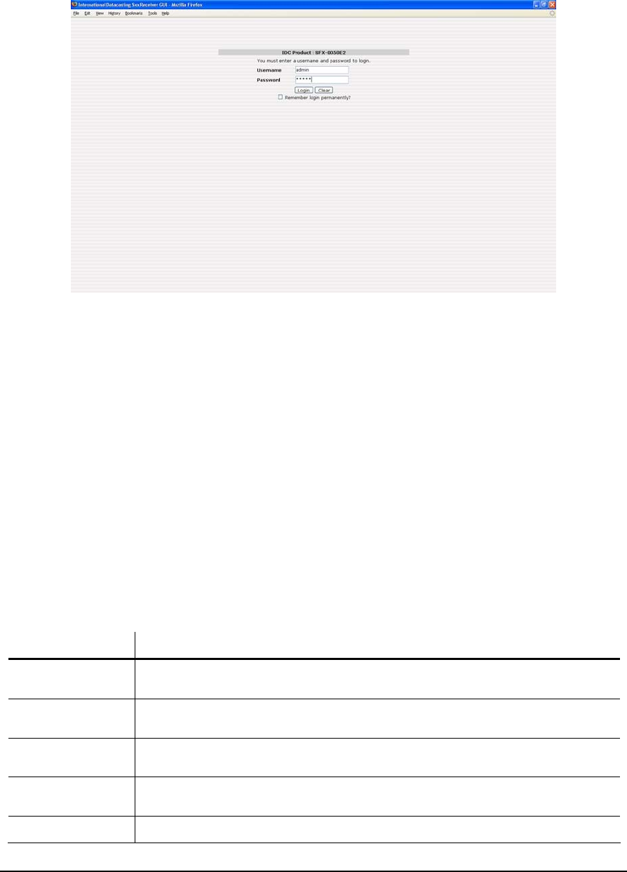
required to login to the receiver, as shown in the example Internet Explorer login page in Figure 1- 4 below.
SFX SERIES USER’S GUIDE
Rev 2.2 17
Figure 1- 4 Login Page
Provided you know the password (contact IDC Customer Service if you don’t – see Chapter 3), login is available at the
following levels:
1. Monitor status only – login as username monitor or user
2. Administrator allows monitor and full control of all receiver functions – login as username admin
Should you enter an incorrect username and/or password; the login page will report an error.
Once you have successfully logged in, the Main Menu page will appear and you are connected to an operational Web
GUI. An example of the Main Menu page is shown in Figure 1- 5. Chapter 2 of this User’s Guide provides details on
navigating the various pages of the Web GUI. Although the information presented in Chapter 2 relates to the operation
of the Web GUI, many of the functions can also be controlled in a similar way with the Front Panel LCD/Keypad and
the Terminal Interface.
The Main Menu Tool Bar across the top of the Main Menu page presents all the main menu options available with this
receiver. This area remains displayed at all times and you can click on any of the tool bar options at any time to return
to a known location in the menu structure. The table below describes each Main Menu Tool Bar item.
Main Menu
Tool Bar Item
Description
Identity Items associated with displaying and/or editing the identity of the receiver, including name,
MAC Addresses, IP addresses, DHCP enable, etc.
DVB Carrier Items associated with the RF tuner/demodulator setup of the satellite receiver, including DVB-
S or DVB-S2 Carrier A/B setup and LNB attributes.
Channel Guide Items associated with the display and editing of audio/data channels as captured by the
receiver (only if channel guide option is enabled and installed in your network).
Data Delivery Items associated with all data delivery to/from the receiver, including PID definitions, multicast
and unicast routing, NAT, IGMP, Firewalling, etc.
XD Items associated with the set up and use of the content distribution software, XD

SFX SERIES USER’S GUIDE
Rev 2.2 18
Main Menu
Tool Bar Item
Description
Logging Items associated with local and remote status logging of receiver events, including RF status
and faults.
Metrics Items associated with RF and data metrics displays.
Configuration Items associated with configuration of web, network and operating system applications on the
receiver.
Utilities Items associated with peripheral utilities required to properly operate the receiver in your
network, including Date/Time, Passwords, Ping, etc. A Documentation menu item under
Utilities provides an electronic copy of the full User’s Guide.
Upgrade Items associated with the upgrade of application firmware and other software applications
required to properly operate the receiver.
The area at the bottom of the Main Menu page provides an updated RF status of the DVB carrier being currently
received. This area remains displayed at all times and RF metrics information presented here is only valid if the DVB
Carrier A/B Lock Status indicates that the receiver is locked to Carrier A or B (green square). This display area is
updated at the periodic refresh rate set by the “Refresh” box (in seconds) at the right of the status bar. The metrics are
displayed separately for each tuner and the content varies with the choice of DVBS or DVBS-2 carriers and the setting
of the Viterbi rate as shown below.
Carrier Type
S S
Auto
Viterbi
S2 S2
Auto RF Metric Description
■ ■ ■ ■ Lock This shows the status of the receiver lock to the selected carrier,
and the locked carrier letter.
■ ■ ■ ■ Redundancy This display provides the current Master/Backup status of the
receiver if it has been configured for redundancy.
■ ■ Signal Quality This display gives an indication of the Quality of the incoming data
stream. This feature is useful to evaluate the quality of the
incoming RF signal. A value from 0% to 100% is shown within the
display. The higher the percentage, the better the Carrier To
Noise (C/No) or quality of the digital carrier. This display is based
on an estimation of incoming noise by the tuner front end and is
accurate to ± 10%.
The display bar changes colour, according to the following:
Black – tuner is not locked to a carrier.
Red – signal quality is too low (1% to 24%).
Green – signal quality is in acceptable operating range (25% to
100%).
■ ■ ■ ■ Signal Level This display provides a percentage of the signal strength of the
DVB carrier that is being received at the L-Band input to the tuner.
The display bar changes colour, according to the following:
Black – tuner is not locked to a carrier.
Red – signal level is too low (1% to 19%) or too high (90% to
100%).
Yellow – signal level is marginally too low (20% to 29%) or

SFX SERIES USER’S GUIDE
Rev 2.2 19
Carrier Type
S S
Auto
Viterbi
S2 S2
Auto RF Metric Description
marginally too high (80% to 89%).
Green – signal level is in the acceptable AGC operating range
(30% to 80%).
■ ■ Eb/No This value represents the calculated Eb/No (in dB) at the input to
the tuner. This value is derived from the C/N value, with
compensation for modulation scheme, Reed-Solomon FEC, Viterbi
FEC rate, and symbol rate of the carrier.
■ ■ ■ ■ C/N This value represents the estimated carrier to noise ratio (in dB) at
the L-Band input to the tuner. The format of this value is x.y dB.
■ Mod Standard Selects the modulation standard as either DVB-S or DVB-S2
■ Viterbi Rate This is the factor used in the FEC of the satellite data for recovery
of data.
■ Code Rate
■ Alpha Factor
■ ■ Viterbi BER This is the number of bit errors encountered during a fixed frame
length of incoming data. This data is obtained from the tuner
demodulator chip and is converted to a BER value in the form x.y
E -z.
■ ■ ■ ■ LNB Offset This indicates what the current LNB offset is, based on the
automatic LNB drift tracking mechanism of the tuner. This value is
added or subtracted from the set frequency in the DVB Carrier
definition to tune to the carrier.
■ ■ ■ ■ Refresh Shows the period of the refresh of the RF metrics on this page.
NOTE: The accuracy of the values reported for C/N and Eb/No are typically ±1 dB up to a C/N of 15 dB (BER of 1 x
10-12). With C/No values higher than 15 dB, the accuracy degrades. (For example, a DVB-S signal can be considered
error free at greater than 7 dB Eb/No at 7/8 Viterbi, 4 dB Eb/No at 1/2 Viterbi).
Controlling the Receiver with SNMP
The Simple Network Management Protocol (SNMP) is a set of protocols for managing complex networks. SNMP
works by sending messages, called Protocol Data Units (PDU’s), to different parts of a network, providing a standard
mechanism for network control and monitoring. SNMP-compliant devices, called agents, store data about themselves
in Management Information Bases (MIB’s) and return this data to the SNMP requestor.
The advantage of using SNMP is that its design is simple, hence it is easy to implement on a large network. It does not
take a long time to set up, puts very little stress on a network and is easy for users to program. Its simple design also
allows it to be easily updated so that it can expand for future network requirements.
SNMP has been implemented in the SFX Series satellite receivers to provide users with flexibility in network
management.

SFX SERIES USER’S GUIDE
Rev 2.2 20
Figure 1- 5 Web GUI Main Menu Page
SNMP can be used to monitor the status, and control the configuration, of a receiver through SNMP get and set
requests. SNMP values are organized in a tree structure called a Management Information Base (MIB). International
Datacasting uses a Private Enterprise Number of 3602 - this is the root node for IDC equipment under the Enterprise
node of the MIB tree, and the number is 1.3.6.1.4.1.3602. In addition to these values the receiver also supports the IP
branch of MIB-II (1.3.6.1.2.1.3) except for the IP Address Translation table.
A separate International Datacasting application note is provided with details on the content of the MIB. Please
proceed to Chapter 3 for more information on obtaining application notes.
Controlling the Receiver with NetManager2
Many accessible functions within the SFX Series satellite receiver can also be controlled over the satellite link, or
through a local Ethernet connection, using International Datacasting’s NetManager2 system. This is a secure control
system that allows the network provider to control functions of the receiver using the Network Control Channel (NCC)
IP stream, encapsulated in the NCC PID or multicast through the receiver Ethernet port. There is potentially one NCC
PID stream per DVB Carrier, and you can configure DVB Carriers using one of the other Status and Control methods
(e.g. LCD/Keypad Interface or Web GUI), so that NetManager2 control can be brought online.
Not all functions can be remotely controlled via NetManager2 over the satellite, as they could be site-specific
configurations. Therefore, these types of functions must be controlled using one of the other means previously
described or by using NetManager2 through a local Ethernet connection on the same subnet as the receiver. To allow
Netmanager2 control through the Ethernet port, the NCC multicast address must be changed to match the NCC
address. The associated port is defaulted to 6000. Please contact International Datacasting Sales or Customer
Support for more information on NetManager2, or using NetManager2 through a local connection (see Chapter 3).

SFX SERIES USER’S GUIDE
Rev 2.2 21
Web GUI Operation
This chapter will provide detailed information on the meaning and operation of the various pages and menu options
available on the Web GUI for the SFX family of receivers.
Main Menu Page
As stated in the previous chapter, once you have successfully logged in to the Web GUI you will be presented with the
Main Menu page as shown in the example in Figure 2- 1. There are various areas of interest on this page, which will
be described in this section.
Logout Icon
The “logout” icon is always present at all menu levels. By clicking on the icon you can quickly logout of the receiver
Web GUI. To login again, follow the procedure outlined in Chapter 1.
IDC Logo
The IDC logo is always present at all menu levels. If your receiver is connected to a gateway to the Internet, then by
clicking on the logo icon you can reach the International Datacasting website at www.Datacast.com. (This link is also
available if you click in the area where the copyright notice appears in the center of the page– Figure 2- 1).
Receiver Identity
The Receiver Identity is displayed only on the Main Menu page after you have successfully logged into the receiver
Web GUI. It provides the name given to the receiver, the type of receiver (e.g. SFX3101) and the version of the main
firmware application running in the unit. The name given to the receiver can be set using the Identity main menu tool
bar item.
Chapter 2

SFX SERIES USER’S GUIDE
Rev 2.2 22
Figure 2- 1 Main Menu Page with Identified Areas
Main Menu Tool Bar Area
The Main Menu Tool Bar presents all the main menu options available with this receiver. This area remains displayed
at all times and you can click on any of the tool bar options at any time to return to a known location in the menu
structure.
Main Display Area
The Main Display Area provides all the dynamic display information for a given menu option. All submenu items and
associated status displays, tables and edit pages are displayed in this area.
Metrics Display Area
The Metrics Display Area presents an updated RF status of the DVB carrier being currently received. This area
remains displayed at all times and metrics information presented here is only valid if the DVB Carrier A/B Lock Status
indicates that the receiver is locked to carrier A or B (green square). This display area is updated at the periodic
refresh rate set by the RF Metrics Refresh Rate (in seconds). The metrics that are displayed were described in
Chapter 1.
Note that this display area can also be switched to display the latest entries of the system log, using the same refresh
interval. To enable this feature you must use the Configuration -> GUI Configuration menu (see later sections of this
chapter).
Logout
Icon
IDC Logo
www.Datacast.com
Main Menu
Tool Bar Area
Receiver
Identity
Metrics
Refresh Rate
Selection
Metrics
Display Area
DVB Carrier A/B
Lock Status
Main
Display
Area
NOTE:
Display updates
in the Main
Display Area
are not affected
by the Metrics
Refresh Rate.
If you wish to
update content
in this area at
any time, you
must use the
Browser
Refresh Button.
Redundancy
Status

SFX SERIES USER’S GUIDE
Rev 2.2 23
Main Menu Tool Bar
The Main Menu Tool Bar provides the top-level menu access for all functions that can be monitored and controlled in
the receiver. The remainder of this chapter will describe these functions, as organized by menu items, shown in the
following menu hierarchy:
Show
Edit
Identity
Back to Main
Cancel Changes
Send Update
DVB Carrier Carrier Status
Edit Carrier A
Edit Carrier B
Copy Carrier A to Carrier B
Copy Carrier B to Carrier A
Lock to Preferred
Back to Main
Cancel Changes
Send Update
DVB Carrier Definitions
Show Attributes
Edit
Reset LNB Offset
LNB Attributes
Back to Main
Cancel Changes
Send Update
CAM/CAS
Show
Edit
With Conditional Access Module
only Back to Main
Cancel Changes
Send Update
Show Channels
Show Selected
Edit
Back to Main
Cancel Changes
Send Update
Channel Guide
Show DNAT Table
Edit DNAT Table
Back to Main
Cancel Changes
Send Update
Destination NAT
Show Filtering Table
Edit Default Rule
Edit Filtering Table
Back to Main
Cancel Changes
Send Update
Filtering
Show Firewall Table
Edit Default Rule
Edit Firewall Table
Back to Main
Cancel Changes
Send Update
Firewall
Show IGMP Net1 (eth0)
Show IGMP Net2 (eth1)
Edit Net1 (eth0)
Edit Net2 (eth1)
Restore Defaults Net1 (eth0)
Restore Defaults Net2 (eth1)
Main Menu
Data Delivery
IGMP
Back to Main
Cancel Changes
Send Update

SFX SERIES USER’S GUIDE
Rev 2.2 24
Show Table
Edit Default Route
Edit Table
Back to Main
Cancel Changes
Send Update
Multicast Routing
PIDs and Ports NET PIDs
ASYNC PIDs
SYNC PIDs
Other PIDs
With ASI Port Option Only ASI Port
Edit Selected
Add New PID Definition
Delete Selected
Delete All
Back to Main
Cancel Changes
Send Update
Source NAT Show SNAT Table
Edit SNAT Table
Back to Main
Cancel Changes
Send Update
Show Table
Edit Table
Back to Main
Cancel Changes
Send Update
Static Routing
Show TTL Table
Edit TTL Table
Back to Main
Cancel Changes
Send Update
TTL Translation
Back to Main
Cancel Changes
Send Update
Windows File Sharing
Show
Edit
Back to Main
Cancel Changes
Send Update
XD Client
Show
Edit
Start DataMan
Stop DataMan
Back to Main
Cancel Changes
Send Update
XD
XD DataMan
Back to Main XD License Info
Show
Edit
Start Retriever
Stop Retriever
Back to Main
Cancel Changes
Send Update
XD Retriever
Show Log
Edit
Clear Log
Back to Main
Cancel Changes
Send Update
Logging

SFX SERIES USER’S GUIDE
Rev 2.2 25
Show Filtering Metrics
Edit Metrics Refresh Interval
Filtering Metrics
Back to Main
Cancel Changes
Send Update
Show Interface Metrics
Edit Metrics Refresh Interval
Interface Metrics
Back to Main
Cancel Changes
Send Update
Network
RF Metrics
HD Space
Performance
MRTG Metrics
Back to Main
Show Multicast Routing Metrics
Edit Metrics Refresh Interval
Multicast Routing Metrics
Back to Main
Cancel Changes
Send Update
Show RF Metrics
Show PID Metrics
Edit Metrics Refresh Interval
Edit RF Metrics Logging Interval
RF Metrics
Back to Main
Cancel Changes
Send Update
Show System Health Metrics
Edit Metrics Refresh Interval
System Health Metrics
Back to Main
Cancel Changes
Send Update
Metrics
Show
Advanced (Apache options)
Back to Main
Cancel Changes
Send Update
Apache
Show
Edit
Channel Guide Configuration
Back to Main
Cancel Changes
Send Update
DHCP Server Advanced DHCP edit options
(Use with caution)
Show
Edit
Back to Main
Cancel Changes
Send Update
Date and Time
Show
Edit
Back to Main
Cancel Changes
Send Update
Ethernet Configuration
Show
Edit
Back to Main
Cancel Changes
Send Update
FTP
Configuration
GUI Configuration Show GUI Configuration
Edit GUI Configuration

SFX SERIES USER’S GUIDE
Rev 2.2 26
Back to Main
Cancel Changes
Send Update
Show
Edit
IPStream Redundancy
With Redundancy Option Only
Back to Main
Cancel Changes
Send Update
Show
Edit
NCC Configuration
Back to Main
Cancel Changes
Send Update
Back to Main
Cancel Changes
Change Password
Password Manager
Show Configuration
Edit Configuration
Set Master
Set Backup
Redundancy Configuration
With Redundancy Option Only
Back to Main
Cancel Changes
Send Update
Show
Edit
SFX Home Page
Back to Main
Cancel Changes
Send Update
Show
Edit
Advanced
SSH
Back to Main
Cancel Changes
Send Update
Show
Edit
Advanced
All Shares Read Only
All Shares Read/Write
Samba
Back to Main
Cancel Changes
Send Update
Show
Edit
Volume Configuration (audio)
Back to Main
Cancel Changes
Send Update
Backup and Restore Back to Main
Backup
Restore IDC Defaults
Restore User Defaults
Restore Backup
Documentation User’s Guide
Back to Main
Show
Edit
Irdeto Decryption
With Irdeto/Softcell Option Only Back to Main
Cancel Changes
Send Update
Utilities
FlexKey
Show
Edit

SFX SERIES USER’S GUIDE
Rev 2.2 27
With FlexKey Option Only Back to Main
Cancel Changes
Send Update
Back to Main Ping Utility PING
Stop PING
Back to Main
RESTART
SHUTDOWN
Restart
TCP/UDP Port Registry Back to Main
Back to Main
Traceroute
Stop Traceroute
Traceroute Utility
Back to Main
Cancel Upgrade
Send Upgrade
Upgrade
The Action of the Mouse
A standard web browser interface is used to access and change the content of pages in the Web GUI. In general,
moving the mouse over an active icon or menu item and clicking the left mouse button will select that item. In the case
of data entry into tables etc., simply place the mouse cursor in the field you wish to edit and left click to select the field
for data entry.
Common Menu Items
Referring to the menu hierarchy in the previous section, you can see at the lowest level that there are three menu
items that repeat throughout the submenus. These three items perform the following:
Menu Item Description
Back to Main No matter where you are, selecting this button will always return you back to the Main Menu
page, as shown in Figure 2- 1.
Cancel Changes When working in an edit page, selecting this button will cancel any edits that have been made
on that edit page and return you back to the display page.
Send Update
(or an action)
This third button is always an action button associated with sending of updates/edits to the
receiver. Selecting this button will always result in some immediate action taken by the
receiver. Usually, the action will be an update to the receiver’s configuration.
Drop-down Selection Boxes
Many edit pages utilize drop-down selection boxes, as shown in the example in Figure 2- 2. Clicking on the arrow to
the right of the current selection in the box causes the current selection, and all other available items to be shown. The
dotted line is used to separate the current selection from all items available. If you move the mouse over the item you
are interested in and click the left mouse button the item will be selected as the new current selection. Clicking on the
current selection or the dotted line always retains the current selection (ie. There will be no change in the current
selection).

SFX SERIES USER’S GUIDE
Rev 2.2 28
Figure 2- 2 Drop-down Selection Box
Identity
When the Identity Main Menu Tool Bar item is selected the Identity page is displayed. This provides information
relating to the identification of the receiver on the network and the current running version of the receiver application
firmware. As well, the revision of the satellite receiver board is provided and may sometimes be required for support
purposes. A sample Identity page is shown in Figure 2- 3.
Aside from the Common Menu Items, the following menu items are available:
Menu Item Description
Show Selecting this button will always return you back to the Identity page, as shown in Figure 2- 3.
Edit Selecting this button will enter the Identity Edit page, as shown in Figure 2- 4. Each edit field
is described after the figure.
The following fields can be edited on the Identity Edit page:
Edit Field Description
Name A meaningful name for the receiver can be entered in this field. Up to 31 characters can be
entered. This name will appear on the Main Menu page in the Receiver Identity area and on the
login page.
Description A meaningful description of the receiver can be entered in this field. Up to 255 characters can be
entered. This description information supplements the name given to the receiver and only
appears when the Identity page is displayed.
IP (Address) The IP address of the associated network interface in dotted decimal notation (e.g. 192.168.0.1).
Each IP address must be unique and should be on a different subnet.
The network interface can be one of net1 (first Ethernet port eth0), net2 (second Ethernet port
eth1), or sat (satellite receiver interface sat0).
Unless default IP addresses have been specifically requested, the factory default IP addresses
are: 192.168.0.1 for the Net1 (eth0) interface, 192.168.1.1 for the Net2 (eth1) interface, and
aa.bb.cc.dd for the satellite (sat0) interface.
Current
Selection
Drop-down Box
List of available items –
select and click on an
item to make it the
Current Selection
Click here to activate
drop-down box

SFX SERIES USER’S GUIDE
Rev 2.2 29
Edit Field Description
Netmask The Netmask of the receiver in dotted decimal notation (e.g. 255.255.255.0).
The factory default netmask is 255.255.255.0.
DHCP Indicates whether DHCP is enabled or disabled.
Dynamic Host Configuration Protocol (DHCP – RFC 2131) is a communications protocol that
allows Network Administrators to centrally manage and automate the assignment of Internet
Protocol (IP) configuration, including IP address, subnet mask and default gateway (see Static
Routing menu item) for Local Area Network (LAN) hosts in an organization’s LAN.
In order for a host (e.g. a SFX3101 receiver) to connect to an organization’s LAN, a unique IP
address must be assigned to it. Without DHCP, the IP configuration must be manually entered
using the edit fields described above. However, if a host has moved to another point on the
network, a new IP configuration may have to be assigned. DHCP lets a Network Administrator
distribute IP configuration from a central point and automatically reconfigures a host when it is
plugged into a different network.
If DHCP has been enabled for a network interface, the IP and Netmask fields will be ignored.
Default Gateway
If required, the IP address of the associated default gateway can be entered, in dotted decimal
notation (e.g. 192.168.0.1).
Figure 2- 3 Identity Page

SFX SERIES USER’S GUIDE
Rev 2.2 31
Figure 2- 5 DVB Carrier Status Page
Figure 2- 6 Carrier Edit Page (Carrier A)
The following fields can be edited on the Carrier Edit page:
Edit Field Description
Description A meaningful name or description for the carrier can be entered in this field. Up to 31
characters can be entered. This name will appear on the DVB Carrier Status Page.
Frequency The L-Band receive frequency of the carrier in Hz, in the numeric range 950000000 -
2150000000 Hz.
Symbol Rate The symbol rate of the carrier in symbols per second. The available range for your receiver
model is shown in Appendix A. The symbol rate entered includes all applied FEC and must be
an exact value.
NOTE:
The carrier lock
status is not
automatically
updated on the
status page.
You must use
the refresh
button on your
browser or the
Carrier Status
button on this
page to update
the lock status.
NOTE:
If only one
carrier is being
used in the
network, both
Carrier A and B
should be set to
that carrier.
This will reduce
the lock time
because the
receiver does
not have to
check for two
different

SFX SERIES USER’S GUIDE
Rev 2.2 32
Edit Field Description
Modulation Standard Selects the modulation standard as either one of DVB-S or DVB-S2 (if your model of receiver is
equipped with the DVB-S2 capability).
Viterbi Rate Selects the Viterbi FEC rate of the carrier, using one of the options based on the Modulation
Standard:
DVB-S: Auto, 1/2, 2/3, 3/4, 5/6, 7/8
DVB-S2: Auto
Alpha Factor ????
NCC PID The PID number of the NetManager2 NCC PID (in decimal or hex), in the numeric range 0x20
to 0x1FFE. Specifying 0 disables the NCC PID.
Enable 22kHz Tone Enables or disables the 0.5vpk-pk 22 kHz tone to the LNB. The 22 kHz tone is used to select
the LO frequency pf a universal LNB. The presence of the 22kHz tone switches the universal
LNB to “hi band” (10.6 GHz); the absence switches the LNB to “lo band” (9.75 GHz).
Polarization Selects the polarization of the LNB by setting the output DC voltage from the receiver to the
LNB using one of the options: h for horizontal (18VDC standard or 15 VDC optional) and v for
vertical (13VDC standard or 11 VDC optional).
LNB Attributes
This submenu allows you to set the parameters for controlling the LNB. All LNB attributes are common to both DVB
Carriers. The LNB Attributes page similar to Figure 2- 7 will be displayed when the LNB Attributes submenu item is
selected. The meaning of each attribute is explained under the Edit LNB Attributes page.
(The LNB Offset)
On the LNB Attributes page, the LNB offset is updated to the current value whenever the page is updated (either
through menu selection or browser refresh). The LNB Offset that is displayed is the stored frequency offset in kHz
between the frequency set by the user (in the DVB Carrier Definitions) and the actual frequency that the receiver is
locked to. Every 10 seconds, the receiver calculates the difference between the set frequency and the frequency
being used by the RF front-end demodulator when it acquired lock. If the difference is greater than five percent of the
symbol rate, this difference is added to the accumulated drift. If the accumulated drift is greater than 1.5 MHz (1500
kHz) it is stored as a positive or negative LNB Offset. This is then displayed on the metrics area at the bottom of the
screen and the LNB Attributes page, when you refresh. During carrier lock, the receiver is tuned to the set frequency
plus this LNB offset. This LNB Offset can be reset to 0.0.
Aside from the Common Menu Items, the following menu items are available:
Menu Item Description
Show Attributes Selecting this button will always return you back to the LNB Attributes page, as shown in
Figure 2- 7. The current LNB offset value in kHz is displayed, as calculated by the receiver as
it compensates for LNB drift.
Edit Selecting this button will enter the Edit LNB Attributes page, as shown in Figure 2- 8.
Reset LNB Offset This will reset the receiver’s internal LNB drift tracking offset frequency back to 0.0 kHz.

SFX SERIES USER’S GUIDE
Rev 2.2 33
Figure 2- 7 LNB Attributes Page
Figure 2- 8 Edit LNB Attributes Page
The following fields can be edited on the Edit LNB Attributes page:
Edit Field Description
Frequency Reversal Enables or disables LNB frequency reversal. Off is the default.
Frequency reversal permits the use of other LNB variants that may use low side Local
Oscillators (LOs) instead of high side LOs. The use of LNBs such as older C-Band type with
low side LOs can cause spectral inversion and this feature can make the LNB appear “normal”
when setting the L-Band frequency of the DVB Carrier using the Carrier Edit <X> page.
NOTE:
The LNB
Attributes are
applicable to
both DVB
Carriers.
Supply Select
turns on or off
the LNB power
supply only.
The voltage
actually being
output is
determined by
the Polarization
setting in the
DVB Carrier
Edit page
NOTE:
The LNB Offset
is not
automatically
updated on the
LNB Attributes
page. You
must use the
refresh button
on your browser
or hit the Show
Attributes
button on this
page, to update
the LNB Offset.

SFX SERIES USER’S GUIDE
Rev 2.2 34
Edit Field Description
Supply Select Enables or disables the LNB power supply, which supplies DC voltage to the LNB from the L-
Band connector on the rear panel. When enabled, the DC voltage output will be determined by
the polarization setting from the Carrier Edit <X> page.
AFC Range The AFC range in Hz, in the numeric range 500 to 2000.0 kHz (0.5 to 2 MHz), in steps of 0.1
kHz. The default value in the receiver is +/- 2000kHz. If this field is set to 0 an AFC range of
10% of the carrier symbol rate will be applied. In the event that the resulting range (produced
by 10% of the carrier symbol rate) is too small, adjust the AFC Range manually here.
Channel Guide
When the Channel Guide Main Menu Tool Bar item is selected the Channel Guide main page is displayed. If this
feature is supported by your network a list of the available audio channels will be shown. The list presents additional
information about each audio channel and avoids you having to know specific multicasts addresses and port numbers
for each channel. This electronic channel guide (ECG) is provided and updated by the Service Provider. If there are no
channels available, or the service is not supported, a message will be displayed on this page. If the ECG is not
configured and enabled under Configuration – sub menu - Channel Guide, no channels will be shown here. A sample
channel guide page is shown in Figure 2- 9.
Figure 2- 9 Channel Guide Main Page
The displayed channels are coloured with the following meaning:
Row Colour Description
None The receiver is authorized for this channel, but is not currently playing it.
Green The receiver is currently playing this channel.
Red The receiver is not authorized to receive the PID needed by this channel.
Aside from the Common Menu Items, the following menu items are available:
NOTE:
To obtain the
ECG you must
set up and
enable the
Channel Guide
Configuration –
see under
menu item
Configuration

SFX SERIES USER’S GUIDE
Rev 2.2 36
Figure 2- 11 Edit Selected Channel
The following fields can be edited on the Edit Selected Channel page:
Edit Field Description
State Select from drop down table between:
Disabled, or
Network Stream, Audio, Video
Forward Allows the data corresponding to the channel guide entry to be forwarded out one or both of the
receiver’s Ethernet ports. In the case of audio, the receiver can play the audio as well as
forwarding it.
Data Delivery
Data Delivery functionality is the heart of the receiver. When the Data Delivery Tool Bar item is selected, a submenu
page appears which provides menu items relating to the routing, filtering, firewalling, address translation and output of
data on the receiver interfaces. These are described in the following paragraphs.
In order to understand how the various data delivery functions work, you should understand the path IP packets will
take as they are processed by the receiver. This data flow is demonstrated in the Data Flow Diagram of Figure 2- 12.
In this flow IP packets originate from two primary sources: the satellite interface (sat0) after PID Filtering and MPE De-
encapsulation, or the network (LAN) interfaces.
As shown in Figure 2- 12, the receiver processes IP packets that enter, leave and pass through it. There is a chain for
each of these paths. Any packet entering the receiver goes through the PREROUTING and INPUT chains. Any
packet that the receiver sends out to the network goes through the OUTPUT and POSTROUTING chains. Any packet
that the receiver picks up on one network and forwards to another goes through the FORWARD chain.
Many of the menu items available under Data Delivery maintain tables that allow you to set up certain rules that govern
the treatment of packets of data that pass through each of these chains. With every packet, the rules in the
appropriate table in the chain are checked to see if any of them match. The first rule that matches decides the
outcome for that packet. If none of the rules match then the default rule or policy of the whole chain will be the final
decision maker.
NOTE:
Channels
coloured red
can NOT be
edited.

SFX SERIES USER’S GUIDE
Rev 2.2 38
PIDs and Ports
This submenu provides all the functions that allow you to setup the PID filtering for all relevant data streams in the DVB
Transport Stream.
(PID Filtering and PID Types)
Up to 250 PID streams can be filtered by the receiver, regardless of type; however there are restrictions on how many
PIDs of a type can be assigned to a port. Aside from special types such as the NetManager2 NCC PID, there are four
types of PIDs, organized in four distinct PID Lists:
1. Net PIDs – these are the IP network data streams that are processed by the IP Stack in the receiver and
forwarded either to internal applications that use IP data, or for output on a network device such as an
Ethernet port. All data in Net PIDs are encapsulated using Multi-Protocol Encapsulation (MPE). Up to 250
PIDs can be assigned to the Net PID List, and enabled for output on the network device port(s), depending
on routing, filtering, firewall rules, etc.
If the Cyphercast option is installed in your receiver, then the ECM/EMM PID required by Cyphercast must be
assigned in the Net PID List.
The Network Control Channel PID is an MPE encapsulated Net type PID as well. However, it is a special
PID, used internally by the receiver to decode NetManager2 control commands. It is setup in the DVB
Carrier Definitions, and will not appear in the Net PID List. However, it will use one of the 250 available PID
filters, if enabled.
2. Async PIDs – these are the data streams that are available for output on the ASYNC (RS-232) port. All data
in an Async PID is encapsulated according to the DVB Asynchronous Data Streaming Format. Up to 250
PIDs can be assigned to the Async PID List, but only one PID can be enabled for output to the ASYNC port
at a time.
3. Sync PIDs – these are the data streams that are available for output on the SYNC (RS-422) port. All data in
a sync PID is RAW, a proprietary method specific to IDC MX series encapsulators. Up to 250 PIDs can be
assigned to the Sync PID List, but only one PID can be enabled for output to the SYNC port at a time.
4. Other PIDs – these are PIDs that are filtered and may be used for other applications, such as the ASI Output
option. These PIDs do not conform to any one of the types and rules above and are not routed to one of the
standard output ports.
5. MPEG over IP PIDS – these are a special category of Other PIDS which are applicable to DVB PIDS only.
This variant allows the entire content of the DVB Transport stream, or a selected number of DVB TS PIDS, to
be output through the network port(s) subject to routing, filtering and firewall rules.
When the PIDs and Ports submenu item is selected, a PID List is displayed on a page similar to Figure 2- 13 to Figure
2- 16. Generally, the Net PID List (Figure 2- 13) will be displayed by default. You can select any other PID list by
pressing one of the PID type buttons on the left of the page (i.e. one of NET PIDs, ASYNC PIDs, SYNC PIDs, Other
PIDs or MPEG over IP PIDS.).
The display fields and columns in the Net PID List (Figure 2- 13) have the following meaning:
Column/Field Description
NET port(s) enabled This is a check box, which is used to enable or disable all NET PIDs from being demultiplexed
by the receiver.
Radio Buttons Clicking on the radio button will select a PID in the list. Once selected, you can use the Edit
Selected button to edit the PID definition, or Delete Selected to delete the PID from the list.
Only one PID can be selected at a time.
NOTE:
Up to 250 PID
streams can be
filtered by the
receiver,
regardless of
type; however,
there are
restrictions on
how many PIDs
of a type can be
assigned to a
port.
Whenever a
PID is inserted
into a PID list, it
will use one PID
filter in the
receiver,
whether that
PID is enabled
for output or
not.

SFX SERIES USER’S GUIDE
Rev 2.2 40
Menu Item Description
PID selected in the list (using the radio button on the left hand side of the list).
Add New PID
Definition Selecting this button will enter the Add New PID Definition page, as shown in Figure 2- 18. This
will add a new PID to the list, so no selection is required.
Delete Selected Selecting this button will remove a selected PID (using the radio button on the left hand side of
the list) from the PID list. PIDs are deleted whether they are enabled or not.
Delete ALL Selecting this button will remove all PIDs from the all the PID lists. All PIDs will be deleted
whether they were enabled or not.
Figure 2- 14 Async PID List Page
The display fields and columns in the Async PID List (Figure 2- 14) have a similar meaning to the Net PID List fields
and columns, with the following exceptions:
Column/Field Description
PID Rate This is the baud rate (bps) that the Async Port will be set to when the data is output from this
PID. Effectively this is the maximum data rate for the data received from this PID – it could be
received from the satellite at a slower rate, but will be output from the Async Port at the baud
rate shown.
No PIDs Enabled Since only one PID can be assigned to the Async Port at any one time, the enable column was
implemented using radio buttons instead of check boxes. Since radio buttons force a single
selection to be made, the valid option of No PIDs Enabled has to be provided, which means no
PIDs are authorized for output on the async port.
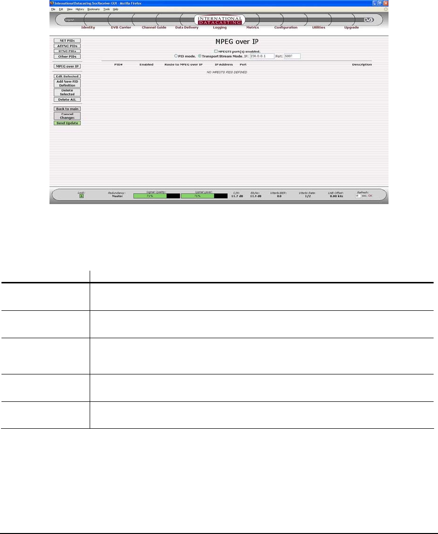
SFX SERIES USER’S GUIDE
Rev 2.2 42
The display fields and columns in the Other PID List (Figure 2- 16) have a similar meaning to the Net PID List fields
and columns, except these are PIDs with no specific port assignment. Additional columns are added when the ASI
Output option is installed, for example and to allow routing as MPEG over IP (see below). See Appendix F for more
information on the ASI Option.
Figure 2- 17 MPEG over IP PID List Page
The display fields and columns in the MPEG over IP PID List have a similar meaning to the Net PID List fields and
columns, with the following exceptions:
Column/Field Description
MPEG TS Port(s)
enabled This is a check box, which is used to enable or disable all MPEG over IP PIDs from being
demultiplexed by the receiver.
PID Mode radio
button This radio button enables the decoding of the PIDs in list shown, from the DVB TS and their
consequent output to the corresponding IP Address and UDP Port shown.
Transport Stream
Mode radio button This radio button selects the decoding of all the PIDs in the DVB Transport Stream (regardless
of the content of the List), and their consequent output to the multicast IP Address and UDP
Port shown. (If the multicast rules allow).
IP / Port This is the multicast address/port combination for the DVB TS only. Individual PIDs use the
address specified during the PID definition.
Route to MPEG over
IP This check box enables/disables the output of the individual PIDs using the MPEG over IP
feature.
NOTE:
MPEG over IP
PIDs have no
inherent routing
and must be
routed to their
desired output
interface by a
Multicast Rule.
Typically one
rule will be
required for
each IP
address used.

SFX SERIES USER’S GUIDE
Rev 2.2 45
Menu Item Description
Query Interval = 125 seconds.
Query Response Interval = 10 seconds.
Last Member Query Interval = 1 seconds.
Last Member Query Count = 2.
Starting Query Interval = 31 seconds.
Starting Query Count = 2.
The individual IGMP variables displayed are explained in the IGMP Edit page section shown below. When the Edit
menu item is selected, the IGMP Edit page will be displayed, as shown by the sample page in Figure 2- 21.
Figure 2- 20 IGMP Page for Net1
The following fields can be edited on the IGMP Edit page:
Edit Field Description
IGMP Enabled A check in this field enables or disables IGMP support. If IGMP is disabled, the receiver outputs
all multicast packets.
IGMP Version Select V1 or V2 IGMP. See IGMP V1 – RFC 1112 and IGMP V2 – RFC 2236.
Robustness Variable This field is related to the expected packet loss on the subnet. IGMP is robust to (Robustness
Variable – 1) packet losses. The default value is 2.
Query Interval This field sets the frequency at which General Queries are sent out on the LAN, via the Ethernet
interface. The default value is 125 seconds.
Query Response
Interval This field sets the amount of time a node on the LAN has to respond to an IGMP query. The
default value is 10 seconds.
Last Member Query
Interval This field sets the maximum response time to a Group-Specific Query that is sent after a Leave
Group Message is received from a node on the LAN. The default value is 1 second.

SFX SERIES USER’S GUIDE
Rev 2.2 49
In addition to the edit fields there are four table row manipulation keys:
Key Description
Add Add the entered information above the table to the table as the last row.
Remove Delete the selected (highlighted) row.
Up If there is more than one row in the table, move the selected row up one row.
Down If there is more than one row in the table, move the selected row down one row.
Multicast Routing
The Multicast Routing submenu maintains the multicasting routing table associated with the receiver. Each receiver
can support up to 200 multicast routes. The multicast routing function is responsible for managing multicast packets
that are traveling through the receiver (host), from external interface to external interface. It is not responsible for
managing multicast packets that are delivered to an application running on the receiver, but the two functions are inter-
related.
Multicast packets are routed through the host according to a multicast routing table that is maintained by the Linux
kernel. Initially, this table is empty and incoming multicast packets are routed according to a default route.
Multicast Routing follows a number of rules, as described in the list below. Many rules are best described by
examples. Many of these rules are more important where a number of local applications may be consuming multicast
packets (e.g. a streaming media decoder).
1. IP packets can originate from any of the available network interfaces and are processed by the receiver in
accordance with the data flow in Figure 2- 12.
2. Up to 200 routes may be entered in the Multicast Routing Table, and order doesn’t matter, assuming that
routes don’t overlap.
3. For assigned routes, IGMP is supported.
4. If a multicast packet is received, whose source IP Address matches the IP Address of one of the receiver’s
network interfaces, that packet is discarded regardless of the current multicast routing rules. This happens
because the receiver assumes it is involved in a multicast loop. For a normal device, this behavior does not
pose a problem, but in a satellite environment, care must be taken to ensure that the source IP address of a
multicast source at the head end does not match the source IP address of any receiver .
The following rules and examples are specialized and are applicable only for Users who are developing their
own applications for the SFX series receivers.
5. Local Application Rule 1: A multicast route is not required in order for a local application program running on
the receiver to receive multicast packets. However, a static route may be needed so that the program can
properly set up a receiving socket. For example, if a program needs to receive multicast data on 224.1.1.1
from the sat0 interface, the following static route must be entered (see Static Routing section of this manual):
Interface: sat0
Gateway: 0.0.0.0
Destination: 224.1.1.1
Netmask: 255.255.255.255
or the more general route could be entered:

SFX SERIES USER’S GUIDE
Rev 2.2 51
lost on the eth1 output. The rule in this case is to bind the static route to an interface that is not being used to
output the multicast traffic (via a multicast route). So in the above example, you must change the static route
to:
Interface: sat0
Gateway: 0.0.0.0
Destination: 224.1.1.1
Netmask: 255.255.255.255
When the Multicast Routing submenu item is selected under Data Delivery, the Multicast Routing page is displayed for
all network interfaces. A sample Multicast Routing page is shown in Figure 2- 24.
Figure 2- 24 Multicast Routing Page
The columns in the Multicast Routing page are described under the Edit Default Route page (Figure 2- 25) and Edit
Multicast Routing Table page (Figure 2- 26
Aside from the Common Menu Items, the following menu items are available:
Menu Item Description
Show Table Selecting this button will always return you back to the Multicast Routing page, as shown in
Figure 2- 24.
Edit Default Route Selecting this button will enter the Edit Default Route page, as shown in Figure 2- 25.
Edit Table Selecting this button will enter the Edit Multicast Routing Table page, as shown in Figure 2- 26.
The following fields can be edited on the Edit Default Route page:
Especificaciones del producto
| Marca: | Max |
| Categoría: | receptor de satélite |
| Modelo: | SFX Series |
¿Necesitas ayuda?
Si necesitas ayuda con Max SFX Series haz una pregunta a continuación y otros usuarios te responderán
receptor de satélite Max Manuales

20 Julio 2024
receptor de satélite Manuales
- receptor de satélite Sony
- receptor de satélite Samsung
- receptor de satélite Grundig
- receptor de satélite Nokia
- receptor de satélite Strong
- receptor de satélite Thomson
- receptor de satélite Trekstor
- receptor de satélite Megasat
- receptor de satélite Manhattan
- receptor de satélite Telestar
- receptor de satélite Technisat
- receptor de satélite Kathrein
- receptor de satélite Devolo
- receptor de satélite Denson
- receptor de satélite Topfield
- receptor de satélite Maxview
- receptor de satélite Zgemma
- receptor de satélite Zehnder
- receptor de satélite Metronic
- receptor de satélite Pure Acoustics
- receptor de satélite Humax
- receptor de satélite Homecast
- receptor de satélite Globo
- receptor de satélite Smart
- receptor de satélite Aston
- receptor de satélite Edision
- receptor de satélite Xoro
- receptor de satélite Maximum
- receptor de satélite SAB
- receptor de satélite Ferguson
- receptor de satélite Reflexion
- receptor de satélite Skymaster
- receptor de satélite M7
- receptor de satélite Dyon
- receptor de satélite Xsarius
- receptor de satélite Octagon
- receptor de satélite Skysat
- receptor de satélite Rebox
- receptor de satélite Helios
- receptor de satélite Schwaiger
- receptor de satélite Boca
- receptor de satélite Inverto
- receptor de satélite Triax
- receptor de satélite Clarke-tech
- receptor de satélite Palcom
- receptor de satélite TechnoTrend
- receptor de satélite ALLvision
- receptor de satélite HD PLUS
- receptor de satélite Travelsat
- receptor de satélite SetOne
- receptor de satélite Oyster
- receptor de satélite Technomate
- receptor de satélite Micro Electronic
- receptor de satélite Axing
- receptor de satélite I-Set
Últimos receptor de satélite Manuales
22 Octubre 2024
20 Octubre 2024
4 Octubre 2024
29 Septiembre 2024
27 Septiembre 2024
22 Septiembre 2024
18 Septiembre 2024
17 Septiembre 2024
15 Septiembre 2024
14 Septiembre 2024