Mitsubishi HC5000 Manual de Usario
Mitsubishi
proyector
HC5000
Lee a continuación 📖 el manual en español para Mitsubishi HC5000 (45 páginas) en la categoría proyector. Esta guía fue útil para 2 personas y fue valorada con 4.5 estrellas en promedio por 2 usuarios
Página 1/45

LCD PROJECTOR
This User Manual is important to you.
Please read it before using your projector.
MODEL
HC5000
User Manual
HC5000

EN-2
The exclamation point within an equilateral triangle is intended to alert the user to the
presence of important operating and maintenance (servicing) instructions in the literature
accompanying the appliance.
CAUTION
RISK OF ELECTRIC SHOCK
DO NOT OPEN
CAUTION: TO REDUCE THE RISK OF ELECTRIC
SHOCK, DO NOT REMOVE COVER (OR BACK)
NO USER-SERVICEABLE PARTS INSIDE
REFER SERVICING TO QUALIFIED SERVICE
PERSONNEL.
The lightning fl ash with arrowhead symbol within an equilateral triangle is intended to alert
the user to the presence of uninsulated “dangerous voltage” within the product’s enclosure
that may be of suffi cient magnitude to constitute a risk of electric shock.
WARNING:
TO PREVENT FIRE OR SHOCK HAZARD, DO NOT EXPOSE THIS APPLIANCE TO RAIN OR MOISTURE.
CAUTION:
TO PREVENT ELECTRIC SHOCK, DO NOT USE THIS (POLARIZED) PLUG WITH AN EXTENSION CORD,
RECEPTACLE OR OTHER OUTLET UNLESS THE BLADES CAN BE FULLY INSERTED TO PREVENT BLADE
EXPOSURE.
NOTE:
SINCE THIS PROJECTOR IS PLUGGABLE EQUIPMENT, THE SOCKET-OUTLET SHALL BE INSTALLED NEAR
THE EQUIPMENT AND SHALL BE EASILY ACCESSIBLE.
WARNING
Use the attached specifi ed power supply cord. If
you use another power supply cord, it may cause
interference with radio and television reception.
Use the attached RGB cable and RS-232C cable with
this equipment so as to keep interference within the
limit of a FCC Class B device.
This apparatus must be grounded.
DO NOT LOOK DIRECTLY INTO THE LENS WHEN
THE PROJECTOR IS IN THE POWER ON MODE.
CAUTION
Not for use in a computer room as defi ned in the
Standard for the Protection of Electronic Computer/
Data Processing Equipment, ANSI/NFPA 75.
When using the projector in Europe:
COMPLIANCE NOTICE
This Projector complies with the requirements of the
EC Directive 89/336/EEC “EMC Directive” as amended
by Directive 92/31/EEC and 93/68/EEC, and 73/23/
EEC “Low Voltage Directive” as amended by Directive
93/68/EEC.
The electro-magnetic susceptibility has been chosen
at a level that gains proper operation in residential
areas, on business and light industrial premises and
on small-scale enterprises, inside as well as outside of
the buildings. All places of operation are characterised
by their connection to the public low voltage power
supply system.
WARNING
Use the attached RGB cable and RS-232C cable with
this equipment so as to keep interference within the
limits of an EN55022 Class B device.
Please follow WARNING instructions.

EN-3
Note: This symbol mark is for EU countries only.
This symbol mark is according to the directive 2002/96/EC Article 10
Information for users and Annex IV.
Declaration of Conformity
Model number: HC5000
Trade name: MITSUBISHI ELECTRIC
Responsible party: Mitsubishi Digital Electronics America, Inc.
9351 Jeronimo Road, Irvine, CA 92618 U.S.A
Telephone number: +1-(949) 465-6000
This device complies with Part 15 of the FCC Rules. Operation is subject to the following two conditions:
(1) this device may not cause harmful interference, and
(2) this device must accept any interference received, including interference that may cause undesired operation.
Trademark, Registered trademark
Macintosh is registered trademark of Apple Computer Inc.
HDMI, the HDMI logo and High-Defi nition Multimedia Interface are trademarks or registered trademarks of HDMI
Licensing LLC.
The “HD ready” logo is a trademark of EICTA.
Other brand or product names are trademarks or registered trademarks of their respective holders.
Your MITSUBISHI ELECTRIC product is designed and manufactured with high quality materials and components
which can be recycled and reused.
This symbol means that electrical and electronic equipment, at their end-of-life, should be disposed of separately
from your household waste.
Please, dispose of this equipment at your local community waste collection/recycling centre.
In the European Union there are separate collection systems for used electrical and electronic product.
Please, help us to conserve the environment we live in!
Contents
Important safeguards ........................................................................................................................4
Preparing your projector ....................................................................................................................6
Using the remote control ...................................................................................................................9
Setting up your projector .................................................................................................................10
Viewing video images ......................................................................................................................13
Viewing computer images ...............................................................................................................21
Menu operation ...............................................................................................................................24
Adjusting projected images .............................................................................................................30
Advanced features ..........................................................................................................................34
Replacing the lamp .........................................................................................................................35
Maintenance ....................................................................................................................................37
Troubleshooting ...............................................................................................................................38
Indicators .........................................................................................................................................41
Specifi cations ..................................................................................................................................42

EN-4
Please read all these instructions regarding your
projector and retain them for future reference. Follow
all warnings and instructions marked on the projector.
Read instructions
All the safety and operating instructions should be
read before the appliance is operated.
Retain instructions
The safety and operating instructions should be
retained for future reference.
Warnings
All warnings on the appliance and in the operating
instructions should be adhered to.
Instructions
All operating instructions must be followed.
Cleaning
Unplug this projector from the wall outlet before
cleaning it. Do not use liquid aerosol cleaners. Use
a damp soft cloth for cleaning.
Attachments and equipment
Never add any attachments and/or equipment
without the approval of the manufacturer as such
additions may result in the risk of fi re, electric
shock or other personal injury.
Water and moisture
Do not use this projector near water or in contact
with water.
Accessories
Do not place this projector on an unstable cart,
stand, tripod, bracket or table. Use only with a
cart, stand, tripod, bracket, or table recommended
by the manufacturer or sold with the projector.
Any mounting of the appliance should follow
the manufacturer’s instructions and should use
a mounting accessory recommended by the
manufacturer.
An appliance and cart combination should be
moved with care. Quick stops, excessive force and
uneven surfaces may cause the appliance and cart
combination to overturn.
Ventilation
Slots and openings in the cabinet are provided
for ventilation, ensuring reliable operation of the
projector and to protect it from overheating. Do not
block these openings or allow them to be blocked
by placing the projector on a bed, sofa, rug, or
bookcase. Ensure that there is adequate ventilation
and that the manufacturer’s instructions have been
adhered to.
1.
2.
3.
4.
5.
6.
7.
8.
9.
Power sources
This projector should be operated only from the
type of power source indicated on the marking
label. If you are not sure of the type of power,
please consult your appliance dealer or local power
company.
Power-cord protection
Power-supply cords should be routed so that
they are not likely to be walked on or pinched
by items placed upon or against them. Pay
particular attention to cords at plugs, convenience
receptacles, and points where they exit from the
appliance. Do not put the power cord under a
carpet.
Overloading
Do not overload wall outlets and extension cords
as this can result in a fi re or electric shock.
Objects and liquids
Never push objects of any kind through openings of
this projector as they may touch dangerous voltage
points or short-out parts that could result in a fi re or
electric shock. Never spill liquid of any kind on the
projector.
Servicing
Do not attempt to service this projector by yourself.
Refer all servicing to qualifi ed service personnel.
Damage requiring service
Unplug this projector from the wall outlet and refer
servicing to qualifi ed service personnel under the
following conditions:
(a) If the power-supply cord or plug is damaged.
(b) If liquid has been spilled, or objects have fallen
into the projector.
(c) If the projector does not operate normally after
you follow the operating instructions. Adjust
only those controls that are covered by the
operating instructions. An improper adjustment
of other controls may result in damage and
may often require extensive work by a qualifi ed
technician to restore the projector to its normal
operation.
(d) If the projector has been exposed to rain or
water.
(e) If the projector has been dropped or the cabinet
has been damaged.
(f) If the projector exhibits a distinct change in
performance - this indicates a need for service.
Replacement parts
When replacement parts are required, be sure
that the service technician has used replacement
parts specifi ed by the manufacturer or parts
having the same characteristics as the original
part. Unauthorized substitutions may result in fi re,
electric shock or other hazards.
Safety check
Upon completion of any service or repair to this
projector, ask the service technician to perform
safety checks determining that the projector is in a
safe operating condition.
10.
11.
12.
13.
14.
15.
16.
17.
Important safeguards

EN-5
WARNING:
Unplug immediately if there is something wrong
with your projector.
Do not operate if smoke, strange noise or odor comes
out of your projector. It might cause fi re or electric
shock. In this case, unplug immediately and contact
your dealer.
Never remove the cabinet.
This projector contains high voltage circuitry. An
inadvertent contact may result in an electric shock.
Except as specifi cally explained in the User Manual do
not attempt to service this product by yourself. Please
contact your dealer when you want to fi x, adjust or
inspect the projector.
Do not modify this equipment.
It can lead to fi re or electric shock.
Do not keep using the damaged projector.
If the projector is dropped and the cabinet is
damaged, unplug the projector and contact your
dealer for inspection. It may lead to fi re if you keep
using the damaged projector.
Do not face the projector lens to the sun.
It can lead to fi re.
Use correct voltage.
If you use incorrect voltage, it can lead to fi re.
Do not place the projector on uneven surface.
Place the projection on a leveled and stable surface only.
Please do not place equipment on unstable surfaces.
Do not look into the lens when it is operating.
It may hurt your eyes. Never let children look into the
lens when it is on.
Do not unplug the power cord during operation.
It can lead to lamp breakage, fi re, electric shock or
other trouble. It is best to wait for the fan to turn off
before turning the main power off.
Do not touch the air outlet grille and bottom plate,
which become hot.
Do not touch them or put other equipment in front
of the air outlet grille. The air outlet grille and bottom
plate, when heated, may cause injury or damage to
other equipment. Also, do not set the projector on the
desk which is easily affected by heat.
Do not look into the air outlet grille when projector
is operating.
Heat, dust, etc. may blow out of it and hurt your eyes.
Do not block the air inlet and outlet grilles.
If they are blocked, heat may be generated inside the
projector, causing deterioration in the projector quality
and fi re.
Do not use fl ammable solvents (benzene, thinner,
etc.) and fl ammable aerosols near the projector.
Flammable substances may ignite causing fi re or
breakdown because the temperature inside the
projector rises very high while the lamp is illuminating.
Place of installation
For safety’s sake, refrain from setting the projector
at any place subjected to high temperature and high
humidity. Please maintain an operating temperature,
humidity, and altitude as specifi ed below.
Operating temperature: between +41°F (+5°C) and
+95°F (+35°C)
Operating humidity: between 30% and 90%
Never put any heat-producing device under the
projector so that the projector does not overheat.
Do not attach the projector to a place that is
unstable or subjected to vibration.
Do not install the projector near any equipment that
produces a strong magnetic fi eld. Also refrain from
installing near the projector any cable carrying a
large current.
Place the projector on a solid, vibration free surface;
otherwise it may fall, causing serious injury to a
child or adult, and serious damage to the product.
Do not stand the projector; it may fall, causing
serious injury and damage to the projector.
Slanting the projector more than ±10°(right and
left) or ±15°(front and rear) may cause trouble or
explosion of the lamp.
Do not place the projector near air-conditioning
unit or heater to avoid hot air to the exhaust and
ventilation hole of the projector.
•
•
•
•
•
•
•
•
•
Important safeguards (continued)
COMPLIANCE NOTICE OF FCC
This equipment has been tested and found to comply with the limits for a Class B digital device, pursuant to Part
15 of the FCC Rules. These limits are designed to provide reasonable protection against harmful interference in a
residential installation. This equipment generates, uses and can radiate radio frequency energy and, if not installed
and used in accordance with the instructions, may cause harmful interference to radio communications. However,
there is no guarantee that interference will not occur in a particular installation. If this equipment does cause
harmful interference to radio or television reception, which can be determined by turning the equipment off and on,
the user is encouraged to try to correct the interference by one or more of the following measures:
Reorient or relocate the receiving antenna.
Increase the separation between the equipment and receiver.
Connect the equipment into an outlet on a circuit different from that to which the receiver is connected.
Consult the dealer or an experienced Radio/TV technician for help.
Changes or modifi cations not expressly approved by Mitsubishi could void the user’s authority to operate this
equipment.
COMPLIANCE NOTICE OF INDUSTRY CANADA
This Class B digital apparatus complies with Canadian ICES-003.
•
•
•
•

EN-6
2
3
Checking accessories
The following accessories are provided with this projector. Check to be sure that all of the accessories are packed in
the package.
CablesPower supply parts
Remote control partsOthers
Lens cap (attached to the projector)
Lamp replacement tray (857C106-10)
User Manual/Quick Start up (English
only) (871D494-10)
CD-ROM (with User Manual)
(919C133-70)
Safety Manual/Quick Start up
(871D393-70)
•
•
•
•
•
Important:
The attached power cords are to be used exclusively for this product. Never use them for other products.•
Inserting the batteries into the remote control
Remove the back lid of the remote control.
Check the polarity (+), (-) of the batteries, and set them
correctly, inserting their (-) side fi rst.
If the battery is inserted from the (+) side fi rst, inserting
the (-) side is diffi cult because the coil spring end hits
on the battery side. If the battery is forced in this way,
the outer label of the battery may get ripped and it may
cause a short-circuit and heating.
Attach the back lid.
Important:
Use two size-AA batteries (R6P).
Replace the two batteries with new ones when the remote
control is slow to respond.
1.
2.
•
3.
•
•
Caution:
Use of a battery of wrong type may cause explosion.
Only Carbon-Zinc or Alkaline-Manganese Dioxide type batteries should be used.
Dispose of used batteries according to your local regulations.
Batteries may explode if misused. Do not recharge, disassemble, or throw them in fi re.
Be sure to handle the batteries according to the instructions.
Load the batteries with its positive (+) and negative (-) sides correctly oriented as indicated on the remote control.
Keep batteries out of reach of children and pets.
Remove the batteries, if the remote control is not used for a long time.
Do not combine a new battery with an old one.
If the solution of batteries comes in contact with your skin or clothes, rinse with water. If the solution comes in
contact with your eyes, rinse them with water and then consult your doctor.
•
•
•
•
•
•
•
•
•
•
Preparing your projector
1
Mini D-SUB
15-pin
Mini D-SUB
15-pin
D-SUB
9-pin
D-SUB
9-pin
RGB cable for PC
(246C521-10)
RS-232C cable
(246C548-10)
Used for projector control
by computer.
•
Power cord (two)
(246C483-10, 246C383-20)
Remote control
(290P150-10)
R6P (Size-AA)
battery (two)
EN-7
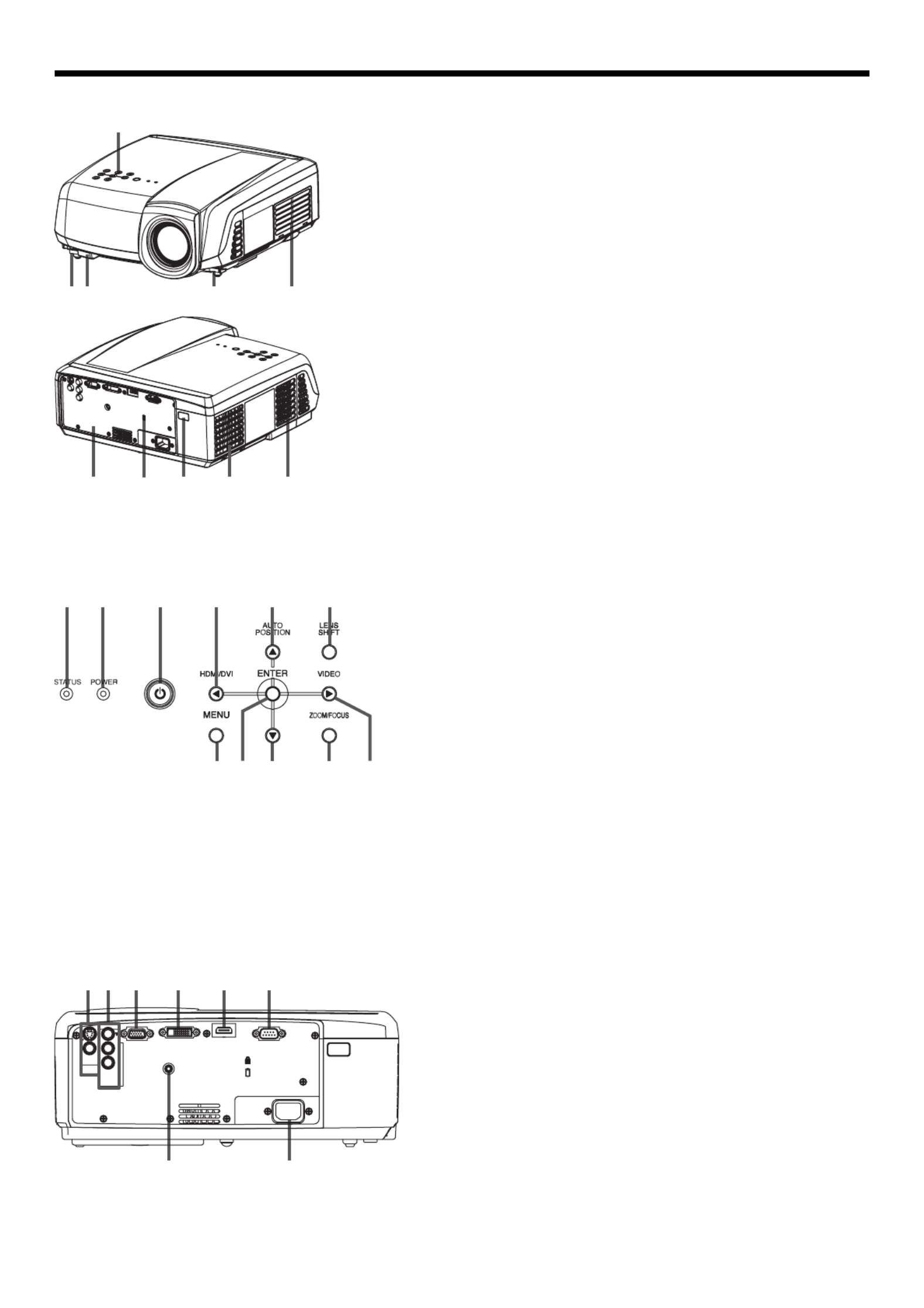
Overview
VIDEO IN and S-VIDEO IN terminals
COMPONENT VIDEO IN terminals
COMPUTER IN/COMPONENT VIDEO IN terminal (Mini
D-SUB 15-pin)
DVI-D(HDCP) IN terminal
HDMI IN terminal (HDMI 19-pin)
SERIAL terminal (D-SUB 9-pin)
Used for projector control by computer. Contact your
dealer for details.
TRIGGER terminal
Used for the optional electric screen.
Power jack
1
2
3
4
5
6
•
7
•
8
STATUS indicator
POWER indicator
POWER button
HDMI/DVI/ buttonW
AUTO POSITION/ buttonS
LENS SHIFT button
MENU button
ENTER button
T button
ZOOM/FOCUS button
VIDEO/ buttonX
Important:
While the menu or the screen for password entry is being
displayed, the HDMI/DVI, VIDEO, and AUTO POSITION
buttons function as the , , and buttons respectively.W X S
1
2
3
4
5
6
7
8
9
10
11
•
Control area
Remote control sensor (Front)
Foot adjustment buttons (Left/Right)
Air inlet grille
Terminal board
Kensington Security Lock Standard connector
Remote control sensor (Rear)
Air outlet grille
1
2
3
4
5
6
7
8
Terminal panel
Control area
Preparing your projector (continued)
1
2
6
5
3 3
87
4
8
1 2 3 4 5 6
97 8 10 11
1 2 3 4 5 6
87
HDMI IN SERIAL
DVI-D(HDCP) IN
TRIGGER
COMPUTER IN/
COMPONENT
VIDEO IN
VIDEO IN
S-VIDEO
IN
P /R
CR
P /B
CB
COMPONENT
VIDEO IN
AC IN

EN-8
Remote control
ON ( I ) button
DVI button
HDMI button
COMPONENT button
AV MEMORY buttons
ENTER button
MENU button
CONTRAST button*
BRIGHTNESS button*
GAMMA button*
ZOOM/FOCUS button
LENS SHIFT button
NOISE REDUCTION button
COLOR button*
SHARPNESS button*
COLOR TEMP button*
ASPECT button
AUTO IRIS button
Direction buttons
VIDEO button
S-VIDEO button
COMPUTER button
AUTO POSITION button
OFF ( ) button
* : See below for the picture quality adjusting buttons.
1
2
3
4
5
6
7
8
9
10
11
12
13
14
15
16
17
18
19
20
21
22
23
24
Adjustment feet1
Bottom side
Using the picture quality adjusting buttons
When you press any of the picture quality adjusting buttons, the screen for adjusting the picture quality appears.
Adjust the picture quality by pressing the and buttons. The picture quality adjustment can be made alternatively W X
in the IMAGE menu. (See page 25.) Items in the menus are shown in parentheses below.
CONTRAST (CONTRAST) ................ Adjusts the contrast of the projected image.
BRIGHTNESS (BRIGHTNESS) ......... Adjusts the brightness of the projected image.
COLOR TEMP (COLOR TEMP.) ........ Selects one of the preset color temperatures. Adjustment of USER mode is also
available. (Refer to page 31.)
GAMMA (GAMMA MODE) ................ Selects one of the preset gamma mode. Adjustment of USER mode is also
available. (Refer to page 32.)
SHARPNESS (SHARPNESS) ............ Adjusts the sharpness of the projected image.
COLOR (COLOR) .............................. Adjusts the color thickness of the projected image.
NOISE REDUCTION ......................... Adjusts the TRNR, MNR and BAR of the projected image. (See page 32.)
Preparing your projector (continued)
11
19
20
17
14
13
12
18
16
22
23
24
21
15
1
2
3
4
5
6
7
8
9
10
11
Important:
When you press any button on the remote control, the buttons on the remote control are lit. Wait approx. 6
seconds after releasing the button to turn them off.
The direction buttons are used for lens shift adjustment. The and buttons are also used for zoom/focus W X
adjustment and fi ne adjustment.
•
•

EN-9
30°30° 30° 30°
Operational range of the remote control
Vertical directions (ceiling mount)
Reception angle
Vertical directions
When operating the remote control, keep the distance
from the remote control to the projector via the screen
within about 5 m (15 feet). The operable range of the
remote control, however, depends on the characteristics
of the screen.
Operate the remote
control within a distance
of 10 m (30 feet) from the
projector, pointing the
IR beam at the remote
control photo-sensor
(front or rear) of the
projector.
Keep the remote control photo-sensor out of direct
sunlight or fl uorescent lamp light.
Keep the remote control photo-sensor at least 2 m
(6 feet) away from fl uorescent lamps. Otherwise,
the remote control may malfunction.
If there is an inverter-operated fl uorescent lamp
near the remote control, the remote control
operation may become unstable.
When you use the remote control too close to the
remote control sensor, the remote control may not
work correctly.
•
•
•
•
Front of projector Rear of projector
Using the remote control
20°
10°
20°
10°
20°
20°
20°
20°
20°
20°
20°
20°
20°
20°

EN-10
Setting up your projector
Setting up the screen
Install the screen perpendicularly to the projector. If the screen can not be installed in such a way, adjust the
projection angle of the projector. (See below.)
Install the screen and projector so that the projector’s lens is placed at the same height and horizontal position of
the screen center.
Do not install the screen where it is exposed to direct sunlight or lighting. Light directly refl ecting on the screen
makes the projected images washed-out and hard to view.
SCREEN SIZE
You can keep the image display area within the screen by setting SCREEN SIZE in the ADVANCED MENU of IMAGE
menu according to the size of the actual screen.
When setting SCREEN SIZE to CINEMA SCOPE(2.35:1):
CinemaScope size movies are projected in the full screen.
Set ASPECT in the FEATURE menu to 16:9 when displaying Vista-size images. In this case, they are squeezed
horizontally.
When ASPECT in the FEATURE menu is set to AUTO and 480i/p, 576i/p, 720p, or 1080i signal is input, the part
for displaying subtitles is not projected. Then, set SCREEN SIZE to 16:9 and adjust the image position using
VERTICAL LOCATION in the ADVANCED MENU of the IMAGE menu. (To display the menu on the screen, adjust
SHUTTER(U) in the SIGNAL - USER menu to position the menu.)
Basic setup
Determine the distance from the screen to the projector according to the size of the images to be projected. (See
page 12.) W
A
A=B
B
Depending on the installation conditions, warm air that is emitted from the exhaust vents may fl ow into the intake
vent, causing the projector to display “TEMPERATURE!!” and then stop projecting images.
•
•
•
•
•
•
LENS SHIFT button
To adjust the positions of the projector and the
screen, use LENS SHIFT button.
Press the LENS SHIFT button.
Press the , , or button to move the S T W X
image position.
Every time the button is pressed, the T
image moves down.
Every time the button is pressed, the S
image moves up.
Every time the button is pressed, the image X
moves to the right.
Every time the button is pressed, the image W
moves to the left.
When you hold down , buttons for 2 S T
seconds or longer, the displayed image moves
fast in the corresponding directions.
Be careful not to be caught in the opening in the
lens while the lens is moving.
When the lens is vertically shifted by a large
amount, color separation may occur.
1.
2.
•
•
•
•
•
•
•
Adjusting the projection angle
This projector is provided with two feet for adjusting
the projection angle on the bottom surface. Adjust
the projection angle depending on the position of
the projector.
Adjustment of the projection angle
For the best projection, project images on a
fl at screen installed at 90 degrees to the fl oor.
If necessary, tilt the projector using the two
adjustment feet on the bottom of the projector.
Adjustment feet
Screen
Tilt up the projector to the appropriate angle.
Press the foot adjustment buttons next to the
adjustment feet, and the adjustment feet will
come out.
Release the buttons to lock the adjustment feet
to that position.
Rotate the adjustment feet for fi ne adjustment.
After using the projector:
Put the adjustment feet back into the projector
by pressing the foot adjustment buttons.
If necessary, rotate the adjustment feet for fi ne
adjustment.
1.
2.
3.
4.
5.
•

EN-12
Screen size and projection distance
Refer to the following table to determine the screen size.
Screen width B
Down side
Up side
50%
50%
SCREEN
Screen height A
(H)
(H)
(L)
Right sideLeft side
(W) (W)
When the aspect ratio of the screen is 4:3
When the aspect ratio of the screen is 4:3, the positional
relation between the projected image and the screen is as
shown on the right. Refer to the following table for installation.
When the aspect ratio of the image is 16:9
Screen size
Size of the projected image
Black
space (D)
Projection distance (L) Lens movable range
Diagonal size Height C Width B Height A Width B Min. Max. (H) (W)
inch cm inch cm inch cm inch cm inch cm inch cm inch m inch m inch cm inch cm
50 127 30 76 40 102 23 57 40 102 4 10 55 1.4 89 2.3 17 43 2 6
60 152 36 91 48 122 27 69 48 122 5 11 66 1.7 108 2.7 20 51 2 6
70 178 42 107 56 142 32 80 56 142 5 13 78 2.0 126 3.2 24 60 3 7
80 203 48 122 64 163 36 91 64 163 6 15 89 2.3 144 3.7 27 69 3 8
90 229 54 137 72 183 41 103 72 183 7 17 101 2.6 163 4.1 30 77 4 9
100 254 60 152 80 203 45 114 80 203 8 19 112 2.9 181 4.6 34 86 4 10
110 279 66 168 88 224 50 126 88 224 8 21 124 3.1 199 5.1 37 94 4 11
120 305 72 183 96 244 54 137 96 244 9 23 135 3.4 218 5.5 41 103 5 12
150 381 90 229 120 305 68 171 120 305 11 29 170 4.3 273 6.9 51 129 6 15
200 508 120 305 160 406 90 229 160 406 15 38 227 5.8 365 9.3 68 171 8 20
250 635 150 381 200 508 113 286 200 508 19 48 285 7.2 456 11.6 84 214 10 25
300 762 180 457 240 610 135 343 240 610 23 57 342 8.7 548 13.9 101 257 12 30
The above fi gures are approximate and may be slightly different from the actual measurements.
Projection distance changes according to the setting of SCREEN SIZE in the ADVANCED MENU in the IMAGE menu. The table above is in the
case of “16:9.”
•
•
When the aspect ratio of the screen is 16:9
Screen size Projection distance (L) Lens movable range
Diagonal size Height A Width B Min. Max. (H) (W)
inch cm inch cm inch cm inch m inch m inch cm inch cm
50 127 25 62 44 111 60 1.5 98 2.5 18 47 2 6
60 152 29 75 52 133 73 1.8 118 3.0 22 56 3 7
70 178 34 87 61 155 85 2.2 138 3.5 26 65 3 8
80 203 39 100 70 177 98 2.5 157 4.0 29 75 3 9
90 229 44 112 78 199 110 2.8 177 4.5 33 84 4 10
100 254 49 125 87 221 123 3.1 197 5.0 37 93 4 11
110 279 54 137 96 244 135 3.4 217 5.5 40 103 5 12
120 305 59 149 105 266 148 3.8 237 6.0 44 112 5 13
150 381 74 187 131 332 185 4.7 297 7.6 55 140 7 17
200 508 98 249 174 443 248 6.3 397 10.1 74 187 9 22
250 635 123 311 218 553 311 7.9 497 12.6 92 233 11 28
300 762 147 374 261 664 373 9.5 597 15.2 110 280 13 33
The above fi gures are approximate and may be slightly different from the actual measurements.
Projection distance changes according to the setting of SCREEN SIZE in the ADVANCED MENU in the IMAGE menu. The table above is in the
case of “16:9.”
•
•
Setting up your projector (continued)
C
A
D D
B

EN-13
HDMI IN SERIAL
DVI-D(HDCP) IN
TRIGGER
COMPUTER IN/
COMPONENT
VIDEO IN
VIDEO IN
S-VIDEO
IN
P /R
CR
P /B
CB
COMPONENT
VIDEO IN
AC IN
DVD player
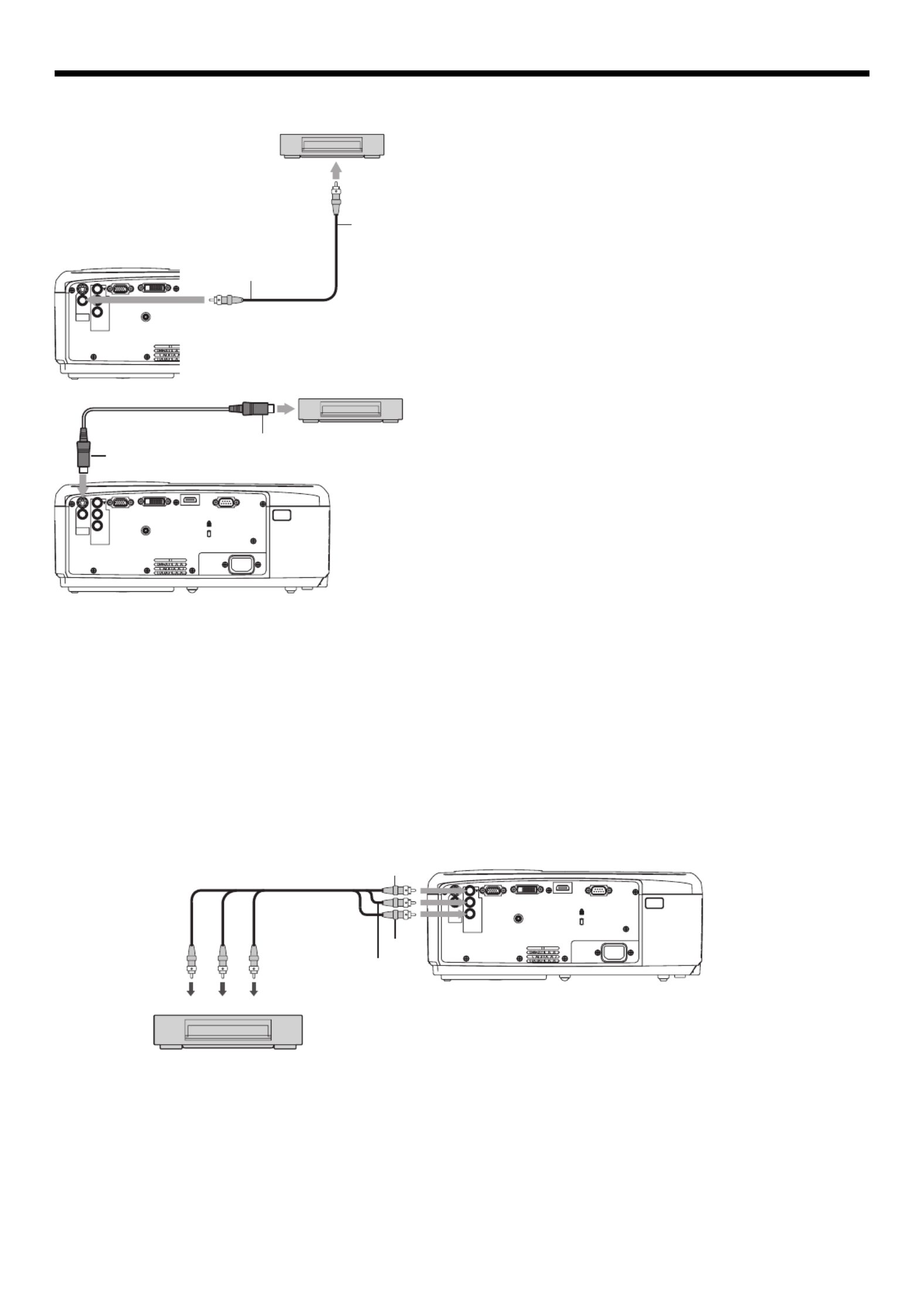
A. Connecting the projector to video equipment
When the projector and the connected devices are located too close to each other, the projected image may be
affected by their interference.
See the owner’s guide of each device for details about its connections.
Preparation:
Make sure that the power of the projector and that of the video equipment are turned off.
Basic home theater system connection
•
•
•
Video player
Set-top box or digital tuner
Viewing video images
EN-14
HDMI IN SERIAL
DVI-D(HDCP) IN
TRIGGER
COMPUTER IN/
COMPONENT
VIDEO IN
VIDEO IN
S-VIDEO
IN
P /R
CR
P /B
CB
COMPONENT
VIDEO IN
AC IN
1
2
1 2
HDMI IN SERIAL
DVI-D(HDCP) IN
TRIGGER
COMPUTER IN/
COMPONENT
VIDEO IN
VIDEO IN
S-VIDEO
IN
P /R
CR
P /B
CB
COMPONENT
VIDEO IN
AC IN
PB/CB
Y
PR/CR
PB/CB
Y
PR R/C
HDMI IN SERIAL
DVI-D(HDCP) IN
TRIGGER
COMPUTER IN/
COMPONENT
VIDEO IN
VIDEO IN
S-VIDEO
IN
P /R
CR
P /B
CB
COMPONENT
VIDEO IN
AC IN
Y
Component cable (option)
Connect one end of the optional video cable to the VIDEO
IN terminal of the projector.
Connect the other end of the video cable to the video
output terminal of the video equipment.
1.
2.
Also read the instruction manual of the equipment to be connected.
Contact your dealer for details of connection.
When a TV tuner or VCR is connected:
When you use this projector with a TV tuner or VCR connected, no image may appear or a message of NO SIGNAL
may appear on the screen when you change the channel via any channel that is not being received. In such a case,
set the channels of the TV tuner or VCR again. To avoid such symptom, use the TV tuner or VCR with its channel skip
function (that is a function not to display channels that are not being received) enabled.
Connecting to a DVD player or HDTV decoder
To connect this projector to video equipment that has component video output terminals, such as a DVD player, use
the COMPONENT VIDEO IN terminals.
•
•
The terminal’s names Y, P
B, and PR are given as examples of when a HDTV decoder is connected.
The terminal’s names vary depending on the connected devices.
Images may not be projected correctly depending on the type of the DVD player you use.
Though it may take some time before an image is displayed on the screen depending on the type of the input
signal, such symptom is not a malfunction.
When connecting a HDTV decoder having RGB output terminals, set COMPUTER INPUT to RGB in the SIGNAL
menu.
•
•
•
•
•
Connecting to a video player, etc.
To video output
terminal
Video cable (option)
S-video cable (option)
To S-VIDEO
IN terminal
To S-video
output terminal
To VIDEO
IN terminal
When the video equipment is equipped with the S-video
output terminal, make the connection as follows:
Connect one end of the optional S-video cable to the
S-VIDEO IN terminal of the projector.
Connect the other end of the S-video cable to the S-video
output terminal of the video equipment.
1.
2.
DVD player or HDTV decoder
Video player, or the like
Video player, or the like
Viewing video images (continued)
Especificaciones del producto
| Marca: | Mitsubishi |
| Categoría: | proyector |
| Modelo: | HC5000 |
¿Necesitas ayuda?
Si necesitas ayuda con Mitsubishi HC5000 haz una pregunta a continuación y otros usuarios te responderán
proyector Mitsubishi Manuales

5 Octubre 2024
2 Octubre 2024
23 Septiembre 2024
19 Septiembre 2024
15 Septiembre 2024
15 Septiembre 2024
9 Septiembre 2024
28 Agosto 2024
27 Agosto 2024
26 Agosto 2024
proyector Manuales
- proyector Sony
- proyector Samsung
- proyector Xiaomi
- proyector Casio
- proyector LG
- proyector HP
- proyector Philips
- proyector Panasonic
- proyector Epson
- proyector JVC
- proyector Toshiba
- proyector Canon
- proyector Acer
- proyector Aiptek
- proyector Anker
- proyector ASK Proxima
- proyector Reflecta
- proyector BenQ
- proyector Sharp
- proyector Leica
- proyector Klarstein
- proyector Hitachi
- proyector Pyle
- proyector Livoo
- proyector Asus
- proyector OK
- proyector Hisense
- proyector Renkforce
- proyector Kodak
- proyector RCA
- proyector 3M
- proyector Overmax
- proyector GPX
- proyector Blaupunkt
- proyector Lenovo
- proyector Polaroid
- proyector Yaber
- proyector Salora
- proyector Optoma
- proyector Sanyo
- proyector Hama
- proyector Nec
- proyector Krüger And Matz
- proyector Steren
- proyector Oki
- proyector Steinel
- proyector Eiki
- proyector Marantz
- proyector Adj
- proyector Barco
- proyector Dahua Technology
- proyector Ion
- proyector Derksen
- proyector Ricoh
- proyector Dell
- proyector InFocus
- proyector Bauer
- proyector Auna
- proyector Planar
- proyector Naxa
- proyector Nebula
- proyector Viewsonic
- proyector Technaxx
- proyector D-Link
- proyector Vivitek
- proyector Emtec
- proyector Celly
- proyector Eurolite
- proyector Smart
- proyector Odys
- proyector Stairville
- proyector Laserworld
- proyector Ibm
- proyector Maxell
- proyector Elmo
- proyector XGIMI
- proyector La Vague
- proyector Speaka
- proyector Kogan
- proyector Cameo
- proyector Tzumi
- proyector EKO
- proyector MicroVision
- proyector Elite Screens
- proyector Celexon
- proyector Prixton
- proyector Fun Generation
- proyector Christie
- proyector PLUS
- proyector Futurelight
- proyector Varytec
- proyector Ultimea
- proyector Dukane
- proyector Dream Vision
- proyector Knoll
- proyector DTS
- proyector Touchjet
- proyector Boxlight
- proyector AAXA Technologies
- proyector Miroir
- proyector Vankyo
- proyector Mimio
- proyector AWOL Vision
- proyector Smart Tech
- proyector Atlantis Land
- proyector KickAss
- proyector Microtek
- proyector Beghelli
- proyector VAVA
- proyector Panamorph
Últimos proyector Manuales
26 Octubre 2024
24 Octubre 2024
24 Octubre 2024
24 Octubre 2024
24 Octubre 2024
24 Octubre 2024
24 Octubre 2024
24 Octubre 2024
24 Octubre 2024
24 Octubre 2024