Suse openSUSE 12.1 Manual de Usario
Lee a continuación 📖 el manual en español para Suse openSUSE 12.1 (450 páginas) en la categoría Software. Esta guía fue útil para 17 personas y fue valorada con 4.5 estrellas en promedio por 2 usuarios
Página 1/450

openSUSE
www.suse.com12.1
December19,2011 Reference
Reference
Copyright © 2006– 2011 Novell, Inc. and contributors. All rights reserved.
Permission is granted to copy, distribute and/or modify this document under the terms of the GNU
Free Documentation License, Version 1.2 or (at your option) version 1.3; with the Invariant Section
being this copyright notice and license. A copy of the license version 1.2 is included in the section
entitled “GNU Free Documentation License”.
For Novell trademarks, see the Novell Trademark and Service Mark list http://www.novell
.com/company/legal/trademarks/tmlist.html. Linux* is a registered trademark of
Linus Torvalds. All other third party trademarks are the property of their respective owners. A trademark
symbol (®, ™ etc.) denotes a Novell trademark; an asterisk (*) denotes a third party trademark.
All information found in this book has been compiled with utmost attention to detail. However, this
does not guarantee complete accuracy. Neither Novell, Inc., SUSE LINUX Products GmbH, the authors,
nor the translators shall be held liable for possible errors or the consequences thereof.
Contents
About This Guide ix
Part I Installation and Deployment 1
1Installation with YaST 3
1.1 Choosing the Installation Media . . . . . . . . . . . . . . . . . . . 3
1.2 Choosing the Installation Method . . . . . . . . . . . . . . . . . . . 5
1.3 The Installation Workow . . . . . . . . . . . . . . . . . . . . . . 8
1.4 System Start-Up for Installation . . . . . . . . . . . . . . . . . . . 9
1.5 TheBootScreen.......................... 9
1.6 Welcome ............................ 12
1.7 InstallationMode......................... 13
1.8 Clock and Time Zone . . . . . . . . . . . . . . . . . . . . . . . 16
1.9 DesktopSelection......................... 17
1.10 Suggested Partitioning . . . . . . . . . . . . . . . . . . . . . . . 17
1.11 CreateNewUser......................... 21
1.12 Installation Settings . . . . . . . . . . . . . . . . . . . . . . . . 25
1.13 Performing the Installation . . . . . . . . . . . . . . . . . . . . . 29
1.14 Conguration of the Installed System . . . . . . . . . . . . . . . . 30
1.15 GraphicalLogin.......................... 35
2Remote Installation 37
2.1 Installation Scenarios for Remote Installation . . . . . . . . . . . . . 37
2.2 Setting Up the Server Holding the Installation Sources . . . . . . . . . 46
2.3 Preparing the Boot of the Target System . . . . . . . . . . . . . . . 55
2.4 Booting the Target System for Installation . . . . . . . . . . . . . . . 65
2.5 Monitoring the Installation Process . . . . . . . . . . . . . . . . . 68
3Advanced Disk Setup 73
3.1 Using the YaST Partitioner . . . . . . . . . . . . . . . . . . . . . 73
3.2 LVMConguration........................ 81
3.3 Soft RAID Conguration . . . . . . . . . . . . . . . . . . . . . . 87
Part II System 91
432-Bit and 64-Bit Applications in a 64-Bit System Environment 93
4.1 RuntimeSupport......................... 93
4.2 Software Development . . . . . . . . . . . . . . . . . . . . . . 94
4.3 Software Compilation on Biarch Platforms . . . . . . . . . . . . . . 95
4.4 Kernel Specications . . . . . . . . . . . . . . . . . . . . . . . 96
5Booting and Conguring a Linux System 97
6The Boot Loader GRUB 99
6.1 BootingwithGRUB........................ 100
6.2 Conguring the Boot Loader with YaST . . . . . . . . . . . . . . . 110
6.3 Uninstalling the Linux Boot Loader . . . . . . . . . . . . . . . . . 116
6.4 CreatingBootCDs........................ 117
6.5 The Graphical SUSE Screen . . . . . . . . . . . . . . . . . . . . 118
6.6 Troubleshooting......................... 119
6.7 For More Information . . . . . . . . . . . . . . . . . . . . . . 120
7Special System Features 121
7.1 Information about Special Software Packages . . . . . . . . . . . . 121
7.2 VirtualConsoles......................... 128
7.3 KeyboardMapping........................ 129
7.4 Language and Country-Specic Settings . . . . . . . . . . . . . . . 129
8Dynamic Kernel Device Management with udev 135
8.1 The /dev Directory....................... 135
8.2 Kernel uevents and udev .................... 136
8.3 Drivers, Kernel Modules and Devices . . . . . . . . . . . . . . . . 136
8.4 Booting and Initial Device Setup . . . . . . . . . . . . . . . . . . 137
8.5 Monitoring the Running udev Daemon............... 138
8.6 Inuencing Kernel Device Event Handling with udev Rules . . . . . . . 139
8.7 Persistent Device Naming . . . . . . . . . . . . . . . . . . . . . 146
8.8 Files used by udev ........................ 147
8.9 For More Information . . . . . . . . . . . . . . . . . . . . . . 147
Part III Services 149
9Basic Networking 151
9.1 IP Addresses and Routing . . . . . . . . . . . . . . . . . . . . . 154
9.2 IPv6—The Next Generation Internet . . . . . . . . . . . . . . . . 157
9.3 NameResolution ........................ 167
9.4 Conguring a Network Connection with YaST . . . . . . . . . . . . 168
9.5 NetworkManager ........................ 189
9.6 Conguring a Network Connection Manually . . . . . . . . . . . . . 192
9.7 smpppd as Dial-up Assistant . . . . . . . . . . . . . . . . . . . . 208
10 SLP Services in the Network 211
10.1 Installation........................... 211
10.2 ActivatingSLP.......................... 212
10.3 SLP Front-Ends in openSUSE . . . . . . . . . . . . . . . . . . . . 212
10.4 Installation over SLP . . . . . . . . . . . . . . . . . . . . . . . 212
10.5 Providing Services via SLP . . . . . . . . . . . . . . . . . . . . . 213
10.6 For More Information . . . . . . . . . . . . . . . . . . . . . . 214
11 The Domain Name System 215
11.1 DNSTerminology........................ 215
11.2 Installation........................... 216
11.3 Conguration with YaST . . . . . . . . . . . . . . . . . . . . . . 216
11.4 Starting the BIND Name Server . . . . . . . . . . . . . . . . . . 227
11.5 The /etc/named.conf Conguration File . . . . . . . . . . . . . . . 228
11.6 ZoneFiles ........................... 233
11.7 Dynamic Update of Zone Data . . . . . . . . . . . . . . . . . . . 237
11.8 Secure Transactions . . . . . . . . . . . . . . . . . . . . . . . 237
11.9 DNSSecurity.......................... 239
11.10 For More Information . . . . . . . . . . . . . . . . . . . . . . 239
12 DHCP 241
12.1 Conguring a DHCP Server with YaST . . . . . . . . . . . . . . . . 242
12.2 DHCP Software Packages . . . . . . . . . . . . . . . . . . . . . 246
12.3 The DHCP Server dhcpd . . . . . . . . . . . . . . . . . . . . . 246
12.4 For More Information . . . . . . . . . . . . . . . . . . . . . . 250
13 Time Synchronization with NTP 251
13.1 Conguring an NTP Client with YaST . . . . . . . . . . . . . . . . 251
13.2 Manually Conguring ntp in the Network . . . . . . . . . . . . . . 256
13.3 Dynamic Time Synchronization at Runtime . . . . . . . . . . . . . . 257
13.4 Setting Up a Local Reference Clock . . . . . . . . . . . . . . . . . 257
14 Sharing File Systems with NFS 259
14.1 Terminology........................... 259
14.2 Installing NFS Server . . . . . . . . . . . . . . . . . . . . . . . 260
14.3 Conguring NFS Server . . . . . . . . . . . . . . . . . . . . . . 260
14.4 Conguring Clients . . . . . . . . . . . . . . . . . . . . . . . . 270
14.5 For More Information . . . . . . . . . . . . . . . . . . . . . . 273
15 Samba 275
15.1 Terminology........................... 275
15.2 Installing a Samba Server . . . . . . . . . . . . . . . . . . . . . 277
15.3 Starting and Stopping Samba . . . . . . . . . . . . . . . . . . . 277
15.4 Conguring a Samba Server . . . . . . . . . . . . . . . . . . . . 277
15.5 Conguring Clients . . . . . . . . . . . . . . . . . . . . . . . . 284
15.6 Samba as Login Server . . . . . . . . . . . . . . . . . . . . . . 285
15.7 For More Information . . . . . . . . . . . . . . . . . . . . . . 286
16 The Apache HTTP Server 287
16.1 QuickStart........................... 287
16.2 Conguring Apache . . . . . . . . . . . . . . . . . . . . . . . 289
16.3 Starting and Stopping Apache . . . . . . . . . . . . . . . . . . . 304
16.4 Installing, Activating, and Conguring Modules . . . . . . . . . . . . 307
16.5 Getting CGI Scripts to Work . . . . . . . . . . . . . . . . . . . . 315
16.6 Setting Up a Secure Web Server with SSL . . . . . . . . . . . . . . 317
16.7 Avoiding Security Problems . . . . . . . . . . . . . . . . . . . . 325
16.8 Troubleshooting......................... 327
16.9 For More Information . . . . . . . . . . . . . . . . . . . . . . 328
17 Setting up an FTP server with YaST 331
17.1 Starting the FTP server . . . . . . . . . . . . . . . . . . . . . . 332
17.2 FTP General Settings . . . . . . . . . . . . . . . . . . . . . . . 333
17.3 FTP Performance Settings . . . . . . . . . . . . . . . . . . . . . 334
17.4 Authentication ......................... 334
17.5 ExpertSettings ......................... 335
17.6 For more information . . . . . . . . . . . . . . . . . . . . . . 335
Part IV Mobility 337
18 Mobile Computing with Linux 339
18.1 Laptops ............................ 339
18.2 MobileHardware ........................ 346
18.3 Cellular Phones and PDAs . . . . . . . . . . . . . . . . . . . . . 347
18.4 For More Information . . . . . . . . . . . . . . . . . . . . . . 348
19 Power Management 349
19.1 Power Saving Functions . . . . . . . . . . . . . . . . . . . . . . 349
19.2 Advanced Conguration and Power Interface (ACPI) . . . . . . . . . . 350
19.3 Rest for the Hard Disk . . . . . . . . . . . . . . . . . . . . . . 356
19.4 Troubleshooting......................... 357
19.5 For More Information . . . . . . . . . . . . . . . . . . . . . . 359
20 Wireless LAN 361
20.1 WLANStandards......................... 361
20.2 OperatingModes........................ 362
20.3 Authentication ......................... 363
20.4 Encryption........................... 364
20.5 Conguration with YaST . . . . . . . . . . . . . . . . . . . . . . 365
20.6 Tips and Tricks for Setting Up a WLAN . . . . . . . . . . . . . . . 373
20.7 Troubleshooting......................... 375
20.8 For More Information . . . . . . . . . . . . . . . . . . . . . . 377
21 Using NetworkManager 379
21.1 Use Cases for NetworkManager . . . . . . . . . . . . . . . . . . 379
21.2 Enabling NetworkManager . . . . . . . . . . . . . . . . . . . . 380
21.3 Conguring Network Connections . . . . . . . . . . . . . . . . . 380
21.4 Using KNetworkManager . . . . . . . . . . . . . . . . . . . . . 384
21.5 Using GNOME NetworkManager Applet . . . . . . . . . . . . . . . 387
21.6 NetworkManager and VPN . . . . . . . . . . . . . . . . . . . . 390
21.7 NetworkManager and Security . . . . . . . . . . . . . . . . . . . 391
21.8 Frequently Asked Questions . . . . . . . . . . . . . . . . . . . . 393
21.9 Troubleshooting......................... 394
21.10 For More Information . . . . . . . . . . . . . . . . . . . . . . 395
22 Using Tablet PCs 397
22.1 Installing Tablet PC Packages . . . . . . . . . . . . . . . . . . . . 398
22.2 Conguring Your Tablet Device . . . . . . . . . . . . . . . . . . . 399
22.3 Using the Virtual Keyboard . . . . . . . . . . . . . . . . . . . . 399
22.4 Rotating Your Display . . . . . . . . . . . . . . . . . . . . . . . 399
22.5 Using Gesture Recognition . . . . . . . . . . . . . . . . . . . . 400
22.6 Taking Notes and Sketching with the Pen . . . . . . . . . . . . . . 403
22.7 Troubleshooting......................... 404
22.8 For More Information . . . . . . . . . . . . . . . . . . . . . . 406
23 Copying and Sharing Files 407
23.1 Scenarios............................ 408
23.2 AccessMethods......................... 409
23.3 Accessing Files Using a Direct Connection . . . . . . . . . . . . . . 410
23.4 Accessing Files on Different OS on the Same Computer . . . . . . . . 412
23.5 Copying Files between Linux Computers . . . . . . . . . . . . . . . 413
23.6 Copying Files between Linux and Windows Computers with SSH . . . . . 420
23.7 Sharing Files between Linux Computers . . . . . . . . . . . . . . . 422
23.8 Sharing Files between Linux and Windows with Samba . . . . . . . . . 425
23.9 For More Information . . . . . . . . . . . . . . . . . . . . . . 428
AAn Example Network 429
BGNU Licenses 431
B.1 GNU General Public License . . . . . . . . . . . . . . . . . . . . 431
B.2 GNU Free Documentation License . . . . . . . . . . . . . . . . . 434
About This Guide
This manual gives you a general understanding of openSUSE®. It is intended mainly
for system administrators and home users with basic system administration knowledge.
Check out the various parts of this manual for a selection of applications needed in ev-
eryday life and in-depth descriptions of advanced installation and conguration scenarios.
Advanced Deployment Scenarios
Learn how to deploy openSUSE from a remote location and become acquainted
with complex disk setup scenarios.
Managing and Updating Software
Understand how to install or remove software with either YaST or using the com-
mand line, how to use the 1-Click Install feature, and how to keep your system up-
to-date.
Administration
Learn how to congure and upgrade openSUSE, how to administrate your system
in text mode, and get to know some important utilities for Linux administrators.
System
Get an introduction to the components of your Linux system and a deeper under-
standing of their interaction.
Services
Learn how to congure the various network and le services that come with
openSUSE.
Mobility
Get an introduction to mobile computing with openSUSE, get to know the various
options for wireless computing and power management.
Many chapters in this manual contain links to additional documentation resources.
These include additional documentation that is available on the system, as well as
documentation available on the Internet.
For an overview of the documentation available for your product and the latest docu-
mentation updates, refer to http://www.novell.com/documentation/
opensuse114 or to the following section.
1 Available Documentation
We provide HTML and PDF versions of our books in different languages. The following
manuals for users and administrators are available on this product:
Start-Up (↑Start-Up)
Guides you step-by-step through the installation of openSUSE from DVD, or from
an ISO image, gives short introductions to the GNOME and KDE desktops including
some key applications running on it. Also gives an overview of LibreOfce and
its modules for writing texts, working with spreadsheets, or creating graphics and
presentations.
Reference (page 1)
Gives you a general understanding of openSUSE and covers advanced system ad-
ministration tasks. It is intended mainly for system administrators and home users
with basic system administration knowledge. It provides detailed information about
advanced deployment scenarios, administration of your system, the interaction of
key system components and the set-up of various network and le services open-
SUSE offers.
Security Guide (↑Security Guide)
Introduces basic concepts of system security, covering both local and network se-
curity aspects. Shows how to make use of the product inherent security software
like AppArmor (which lets you specify per program which les the program may
read, write, and execute) or the auditing system that reliably collects information
about any security-relevant events.
System Analysis and Tuning Guide (↑System Analysis and Tuning Guide)
An administrator's guide for problem detection, resolution and optimization. Find
how to inspect and optimize your system by means of monitoring tools and how
to efciently manage resources. Also contains an overview of common problems
and solutions and of additional help and documentation resources.
Virtualization with KVM (↑Virtualization with KVM)
This manual offers an introduction to setting up and managing virtualization with
KVM (Kernel-based Virtual Machine) on openSUSE. Also shows how to manage
VM Guests with libvirt and QEMU.
xReference
Find HTML versions of most product manuals in your installed system under /usr/
share/doc/manual or in the help centers of your desktop. Find the latest documen-
tation updates at http://www.novell.com/documentation where you can
download PDF or HTML versions of the manuals for your product.
2 Feedback
Several feedback channels are available:
Bugs and Enhancement Requests
To report bugs for a product component, or to submit enhancement requests, please
use https://bugzilla.novell.com/. For documentation bugs, submit a
bug against the component Documentation for the respective product.
If you are new to Bugzilla, you might nd the following articles helpful:
•http://en.opensuse.org/openSUSE:Submitting_bug_reports
•http://en.opensuse.org/openSUSE:Bug_reporting_FAQ
User Comments
We want to hear your comments and suggestions about this manual and the other
documentation included with this product. Use the User Comments feature at the
bottom of each page in the online documentation or go to http://www.novell
.com/documentation/feedback.html and enter your comments there.
3 Documentation Conventions
The following typographical conventions are used in this manual:
•/etc/passwd: directory names and lenames
•placeholder: replace placeholder with the actual value
•PATH: the environment variable PATH
•ls,--help: commands, options, and parameters
About This Guide xi
•user: users or groups
•Alt,Alt +F1: a key to press or a key combination; keys are shown in uppercase as
on a keyboard
•File,File >Save As: menu items, buttons
•Dancing Penguins (Chapter Penguins, ↑Another Manual): This is a reference to a
chapter in another manual.
4 About the Making of This Manual
This book is written in Novdoc, a subset of DocBook (see http://www.docbook
.org). The XML source les were validated by xmllint, processed by xsltproc,
and converted into XSL-FO using a customized version of Norman Walsh's stylesheets.
The nal PDF is formatted through XEP from RenderX. The open source tools and the
environment used to build this manual are available in the package susedoc that is
shipped with openSUSE.
5 Source Code
The source code of openSUSE is publicly available. Refer to http://en.opensuse
.org/Source_code for download links and more information.
6 Acknowledgments
With a lot of voluntary commitment, the developers of Linux cooperate on a global
scale to promote the development of Linux. We thank them for their efforts—this dis-
tribution would not exist without them. Furthermore, we thank Frank Zappa and Pawar.
Special thanks, of course, goes to Linus Torvalds.
Have a lot of fun!
Your SUSE Team
xii Reference
Part I. Installation and
Deployment
1
Installation with YaST
Install your openSUSE® system with YaST, the central tool for installation and con-
guration of your system. YaST guides you through the installation process and the basic
conguration of your system. During the installation and conguration process, YaST
analyzes both your current system settings and your hardware components and proposes
installation settings based on this analysis. By default, YaST displays an overview of
all installation steps on the left hand side of the window and provides online help texts
for each step. Click Help to view the help text.
If you are a rst-time user of openSUSE, you might want to follow the default YaST
proposals in most parts, but you can also adjust the settings as described here to ne-
tune your system according to your preferences. Many parts of the basic system con-
guration, such as user accounts or system language, can also be modied after the in-
stallation process.
1.1 Choosing the Installation Media
When installing openSUSE, choose from several media available either online or in
the retail box:
DVD-retail
One DVD containing the openSUSE distribution for 32bit and 64bit systems. The
second medium contains proprietary add-on software.
This installation option does not require any network access for installation, nor
do you need to set up external repositories to install the full openSUSE. You can,
Installation with YaST 3

however, make the contents of the DVD available on an installation server and
make them available all across your network.
DVD-download
One DVD5, available via download for 32bit or 64bit systems.
Choose this installation option if you want a fully-edged openSUSE system. Be-
yond the downloading of the DVD ISO, there is no network connection required
to make use of this installation option. Once the medium has been fully downloaded
and the physical medium created, you can go ahead with the installation. You can
also make the contents of the DVDs available on an installation server and make
them available all across your network.
KDE4/GNOME LiveCD
The LiveCD versions, available via download, include the KDE4 or GNOME
desktops together with the most popular applications for 32-bit or 64-bit systems.
Choose this medium option for a rst look at openSUSE. The LiveCD version runs
on your computer using RAM without touching your hard drive and no installation
is needed. However, you can also install openSUSE from the running live system.
There is no network connection required beyond the mere downloading of the
medium.
TIP: Booting the LiveCD from an USB Stick
Live CD iso images can also be used as boot images for USB sticks. Create
a bootable USB stick by using the command-line program dd with the fol-
lowing syntax:
dd if=ISO_IMAGE of=USB_STICK_DEVICE bs=4M
dd is available on Linux and MacOS by default. A Microsoft Windows*
version can be downloaded from http://www.chrysocome.net/dd.
Warning: Using this dd command will erase all data on the USB device!
Mini CD
The Mini CD contains the minimal Linux system needed to run the installation.
The installation system itself and the installation data are loaded from a network
source. To install from a network providing SLP, please start the installation as
described in Section 1.2.1, “Installing from a Network Server Using SLP” (page 7).
4Reference

To install from a HTTP, FTP, NFS, or SMB server, follow the instructions in
Section 1.2.2, “Installing from a Network Source without SLP” (page 7).
IMPORTANT: Add-On CDs—Installing Additional Software
Although add-on CDs (extensions or third-party products) cannot be used as
stand-alone installation media, they can be embedded as additional software
sources during the installation. Currently CDs with additional languages and
non open source software are available as add-on CDs for openSUSE. Refer to
Section 1.7.1, “Add-On Products” (page 14) for more information.
1.2 Choosing the Installation Method
After having selected the installation medium, determine the suitable installation method
and boot option that best matches your needs:
Installing from the openSUSE Media
Choose this option if you want to perform a stand-alone installation and do not
want to rely on a network to provide the installation data or the boot infrastructure.
The installation proceeds exactly as outlined in Section 1.3, “The Installation
Workow” (page 8).
Installing from the LiveCD
In order to install from a LiveCD, boot the live system from CD. In the running
system, launch the installation routine by clicking on the Install icon on the desktop.
Phase one of the installation will be carried out in a window on the desktop. It is
not possible to update an existing system with a LiveCD, you can only perform a
new installation (with automatic conguration).
Installing from a Network Server
Choose this option if you have an installation server available in your network or
want to use an external server as the source of your installation data. This setup
can be congured to boot from physical media (Floppy, CD/DVD, or hard disk)
or congured to boot via network using PXE/BOOTP. Refer to Section 1.2.1,
“Installing from a Network Server Using SLP” (page 7), Section 1.2.2, “Installing
from a Network Source without SLP” (page 7), or Chapter 2, Remote Installation
(page 37) for details.
Installation with YaST 5

Installing with openSUSE 12.1 Installer from Windows
Choose this installation option if you prefer a smooth transition from using Windows
to using Linux. openSUSE 12.1 Installer allows you to boot into the
openSUSE installation right from a running Windows by modifying the Windows
boot loader. This installation option is only available from the DVD media. Refer
to Section 1.2.3, “Installing with the openSUSE 12.1 Installer from
Windows” (page 8) for details.
openSUSE supports several different boot options from which you can choose, depending
on the hardware available and on the installation scenario you prefer. Booting from the
openSUSE media or using openSUSE 12.1 Installer are the most straightfor-
ward options, but special requirements might call for special setups:
Table 1.1 Boot Options
DescriptionBoot Option
This is the easiest boot option. This option can be used if the
system has a local DVD-ROM drive that is supported by Linux.
DVD
openSUSE 12.1 Installer is installed under Microsoft Windows
and makes it possible to boot directly into the installation
openSUSE 12.1
Installer
Booting over the network must be supported by the system's BIOS
or rmware, and a boot server must be available in the network.
PXE or BOOTP
This task can also be handled by another openSUSE system. See
http://en.opensuse.org/SDB:PXE_boot
_installation for more information.Refer to Chapter 2,
Remote Installation (page 37) for more information.
openSUSE installation can also be booted from the hard disk. To
do this, copy the kernel (linux) and the installation system
Hard Disk
(initrd) from the directory /boot/architecture/on the
installation media to the hard disk and add an appropriate entry
to the existing boot loader of a previous openSUSE installation.
6Reference

TIP: Booting from DVD on UEFI machines
►amd64 em64t: DVD1 can be used as a boot medium for machines equipped
with UEFI (Unied Extensible Firmware Interface). Refer to your vendor's doc-
umentation for specic information. If booting fails, try to enable CSM (Com-
patibility Support Module) in your rmware. ◄
1.2.1 Installing from a Network Server Using
SLP
If your network setup supports OpenSLP and your network installation source has been
congured to announce itself via SLP (described in Section 2.2, “Setting Up the Server
Holding the Installation Sources” (page 46)), boot the system, press F4 in the boot
screen and select SLP from the menu.
The installation program congures the network connection with DHCP and retrieves
the location of the network installation source from the OpenSLP server. If the automatic
DHCP network conguration fails, you are prompted to enter the appropriate parameters
manually. The installation then proceeds as described below with the exception of the
network conguration step that is needed prior to adding additional repositories. This
step is not needed as the network is already congured and active at this point.
1.2.2 Installing from a Network Source
without SLP
If your network setup does not support OpenSLP for the retrieval of network installation
sources, boot the system and press F4 in the boot screen to select the desired network
protocol (NFS, HTTP, FTP, or SMB/CIFS). Provide the server's address and the path
to the installation media.
The installation program automatically congures the network connection with DHCP.
If this conguration fails, you are prompted to enter the appropriate parameters manu-
ally. The installation retrieves the installation data from the source specied. The instal-
lation then proceeds as described below with the exception of the network conguration
step needed prior to adding additional repositories. This step is not needed as the network
is already congured and active at this point.
Installation with YaST 7

1.2.3 Installing with the openSUSE 12.1
Installer from Windows
openSUSE 12.1 Installer is a Microsoft Windows application that prepares
your computer to directly boot into the openSUSE installation without having to adjust
BIOS settings. It is only available on DVD media. To use the installer, insert the
openSUSE media under Windows. The openSUSE 12.1 Installer setup automati-
cally starts (if not, run openSUSE11_2_LOCAL.exe from the DVD). Choose a
language for the installation and follow the instructions on the screen. The language
you choose here is also precongured to be used for the openSUSE installation.
On the next reboot, the Microsoft Windows boot loader launches. Choose openSUSE
12.1 Installer to start the openSUSE installation. In order to proceed with the installation,
you will be prompted to insert the installation media. The installation proceeds as de-
scribed below. When Microsoft Windows is booted again, openSUSE 12.1
Installer is automatically uninstalled.
TIP: Installing openSUSE alongside Microsoft Windows
openSUSE can easily be installed alongside Microsoft Windows. Carry out the
installation as described below—an existing Windows installation will automat-
ically be detected and a dual boot option will be installed. If Windows covers
the whole installation disk, the installation routine will make a proposal to
shrink an existing Windows partition in order to make room for the openSUSE.
Please read Section 1.10.1.1, “Resizing a Windows Partition” (page 19) prior to
the installation for detailed information.
1.3 The Installation Workow
The openSUSE installation is split into three main parts: preparation, installation, and
conguration. During the preparation phase you congure some basic parameters such
as language, time, desktop type, users, passwords, hard disk setup and installation scope.
In the non-interactive installation phase the software is installed and the system is pre-
pared for the rst boot. Upon nishing the installation the machine reboots into the
newly installed system and starts the nal system conguration. You can choose whether
8Reference
to do a fully automatic or a manual conguration. In this stage, network and Internet
access, as well as hardware components such as printers, are set up.
1.4 System Start-Up for Installation
You can install openSUSE from local installation sources, such as the openSUSE CDs
or DVD, or from network source of an FTP, HTTP, NFS, or SMB server. Any of these
approaches requires physical access to the system to install as well as user interaction
during the installation. The installation procedure is basically the same regardless of
the installation source. Any exceptions are sufciently highlighted in the following
workow description.
1.5 The Boot Screen
The boot screen displays a number of options for the installation procedure. Boot from
Hard Disk boots the installed system and is selected by default, because the CD is often
left in the drive. Select one of the other options with the arrow keys and press Enter to
boot it. The relevant options are:
Installation
The normal installation mode. All modern hardware functions are enabled. In case
the installation fails, see F5Kernel (page 11) for boot options that disable poten-
tially problematic functions.
Rescue System
Starts a minimal Linux system without a graphical user interface. For more infor-
mation, see Section “Using the Rescue System” (Appendix A, Help and Trou-
bleshooting, ↑Start-Up). This option is not available on LiveCDs.
Check Installation Media
This option is only available when you install from media created from downloaded
ISOs. In this case it is recommended to check the integrity of the installation
medium. This option starts the installation system before automatically checking
the media. In case the check was successful, the normal installation routine starts.
If a corrupt media is detected, the installation routine aborts.
Installation with YaST 9

Firmware Test
Starts a BIOS checker that validates ACPI and other parts of your BIOS. This option
is not available on the LiveCDs.
Memory Test
Tests your system RAM using repeated read and write cycles. Terminate the test
by rebooting. For more information, see Section “Fails to Boot” (Appendix A, Help
and Troubleshooting, ↑Start-Up). This option is not available on the LiveCDs.
Figure 1.1 The Boot Screen
Use the function keys indicated in the bar at the bottom of the screen to change the
language, screen resolution, installation source or to add an additional driver from your
hardware vendor:
F1Help
Get context-sensitive help for the active element of the boot screen. Use the arrow
keys to navigate, Enter to follow a link, and Esc to leave the help screen.
F2Language
Select the display language and a corresponding keyboard layout for the installation.
The default language is English (US).
10 Reference

F3Video Mode
Select various graphical display modes for the installation. Select Text Mode if the
graphical installation causes problems.
F4Source
Normally, the installation is performed from the inserted installation medium. Here,
select other sources, like FTP or NFS servers. If the installation is deployed on a
network with an SLP server, select an installation source available on the server
with this option. Find information about SLP in Chapter 10, SLP Services in the
Network (page 211).
F5Kernel
If you encounter problems with the regular installation, this menu offers to disable
a few potentially problematic functions. If your hardware does not support ACPI
(advanced conguration and power interface) select No ACPI to install without
ACPI support. No local APIC disables support for APIC (Advanced Programmable
Interrupt Controllers) which may cause problems with some hardware. Safe Settings
boots the system with the DMA mode (for CD/DVD-ROM drives) and power
management functions disabled.
If you are not sure, try the following options rst: Installation—ACPI Disabled or
Installation—Safe Settings. Experts can also use the command line (Boot Options)
to enter or change kernel parameters.
F6Driver
Press this key to notify the system that you have an optional driver update for
openSUSE. With File or URL, load drivers directly before the installation starts.
If you select Yes, you are prompted to insert the update disk at the appropriate point
in the installation process.
F7Arch
If you install from an installation medium supporting 32bit and 64bit architectures
and have a processor with 64-bit support, select whether to install a 64-bit or 32-
bit system. By default, a 64-bit system is installed on a computer with 64-bit support.
To install a 32-bit system, press F7 then select 32bit.
TIP: Using IPv6 during the Installation
By default you can only assign IPv4 network addresses to your machine. To
enable IPv6 during installation, enter one of the following parameters at the
Installation with YaST 11

bootprompt: ipv6=1 (accept IPv4 and IPv6) or ipv6only=1 (accept IPv6
only).
After starting the installation, openSUSE loads and congures a minimal Linux system
to run the installation procedure. To view the boot messages and copyright notices
during this process, press Esc. On completion of this process, the YaST installation
program starts and displays the graphical installer.
TIP: Installation without a Mouse
If the installer does not detect your mouse correctly, use Tab for navigation,
arrow keys to scroll, and Enter to conrm a selection. Various buttons or selec-
tion elds contain a letter with an underscore. Use Alt +Letter to select a button
or a selection directly instead of navigating there with the Tab button.
1.6 Welcome
Start the installation of openSUSE by choosing your language. Changing the language
will automatically preselect a corresponding keyboard layout. Override this proposal
by selecting a different keyboard layout from the drop-down menu. The language se-
lected here is also used to assume a time zone for the system clock. This setting—along
with the selection of secondary languages to install on your system—can be modied
later in the Installation Summary, described in Section 1.12, “Installation Settings”
(page 25). For information about language settings in the installed system, see Chap-
ter 11, Changing Language and Country Settings with YaST (↑Start-Up).
Read the license agreement that is displayed beneath the language and keyboard selection
thoroughly. Use License Translations... to access translations. If you agree to the terms,
click Next to proceed with the installation. If you do not agree to the license agreement
click Abort to terminate the installation.
12 Reference
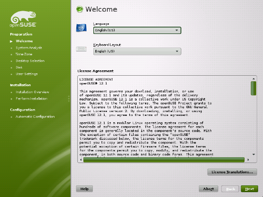
Figure 1.2 Welcome
1.7 Installation Mode
After a system analysis (where YaST probes for storage devices and tries to nd other
installed systems on your machine) the available installation modes are displayed. This
step is skipped when installing from a LiveCD, since this medium only supports a new
installation with automatic conguration.
New installation
Select this option to start a new installation from scratch.
Update
Select this option to update an existing installation to a newer version. For more
information about system updates, see Chapter 16, Upgrading the System and
System Changes (↑Start-Up).
Installation with YaST 13

Figure 1.3 Installation Mode
By default, the automatic conguration is used when performing a new installation. In
this mode the system automatically congures your hardware and the network, so the
installation is performed with minimal user interaction. If necessary, you can change
every conguration that is set up later in the installed system using YaST. Uncheck
Use Automatic Conguration if you prefer a manual conguration during the installation.
Check Include Add-On Products from Separate Media to include add-on products
during the installation. An add-on product can include extensions, third-party products
or additional software for your system such as support for additional languages.
Click Next to proceed. If you selected to include an add-on product, proceed with Sec-
tion 1.7.1, “Add-On Products” (page 14), otherwise skip the next section and advance
to Section 1.8, “Clock and Time Zone” (page 16).
1.7.1 Add-On Products
Add-on products can be installed either from a local source (CD, DVD, or directory)
or from a network source (HTTP, FTP, NFS, CIFS,...). When installing from a network
source, you need to congure the network rst (unless you are performing a network
installation— in this case the existing network conguration is used). Choose Yes, Run
14 Reference
the Network Setup and proceed as described in Section 1.7.1.1, “Network Setup”
(page 15). If the add-on product is available locally, select No, Skip the Network Setup.
Click Next and specify the product source. Source types available are CD,DVD,Hard
Disk,USB Mass Storage, a Local Directory or a Local ISO Image (if no network was
congured). If the add-on product is available on removable media, the system automat-
ically mounts the media and reads its contents. If the add-on product is available on
hard disk, choose Hard Disk to install from an unmounted hard drive, or Local Direc-
tory/Local ISO Image to install from the local le system. Add-on products may be
delivered as a repository or as a set of rpm les. In the latter case, check Plain RPM
Directory. Whenever a network is available, you can choose from additional remote
sources such as HTTP, SLP, FTP, etc. It is also possible to specify a URL directly.
Check Download Repository Description Files to download the les describing the
repository now. If unchecked, they will be downloaded once the installation starts.
Proceed with Next and insert a CD or DVD if required. Depending on the product's
content it may be necessary to accept additional license agreements.
It is also possible to congure add-on products later. Using add-on products on the in-
stalled system is described in Chapter 8, Installing Add-On Products (↑Start-Up).
1.7.1.1 Network Setup
When invoking the network setup, YaST scans for available network cards. If more
than one network card is found, you must choose the card to congure from the list.
If an ethernet network adapter is not already connected, a warning will open. Make
sure the network cable is plugged in and choose Yes, Use It. If your network is equipped
with a DHCP server, choose Automatic Address Setup (via DHCP). To manually set
up the network choose Static Address Setup and specify IP Address,Netmask,Default
Gateway IP, and the DNS Server IP.
Some networks require the use of a proxy server to access the Internet. Tick the check
box Use Proxy for Accessing the Internet and enter the appropriate specications. Click
Accept to perform the network setup. The installation procedure will continue with the
add-on products or repositories setup as described in Section 1.7.1, “Add-On Products”
(page 14).
Installation with YaST 15

1.8 Clock and Time Zone
In this dialog, select your region and time zone. Both are preselected according to the
selected installation language. To change the preselected values, either use the map or
the drop down lists for Region and Time Zone. When using the map, point the cursor
at the rough direction of your region and left-click to zoom. Now choose your country
or region by left-clicking. Right-click to return to the world map.
Figure 1.4 Clock and Time Zone
To set up the clock, choose whether the Hardware Clock is Set to UTC. If you run an-
other operating system on your machine, such as Microsoft Windows, it is likely your
system uses local time instead. If you only run Linux on your machine, set the hardware
clock to UTC and have the switch from standard time to daylight saving time performed
automatically.
If a network is already congured, the time is automatically synced via Network Time
Protocol (NTP) with a time server. Click Change to either alter the NTP settings or to
Manually set the time. See Chapter 13, Time Synchronization with NTP (page 251) for
more information on conguring the NTP service. When nished, click Accept to
continue the installation.
16 Reference

1.9 Desktop Selection
In openSUSE, you can choose from various desktops. The major ones, KDE and
GNOME, are powerful graphical desktop environments similar to Windows. This step
is skipped when installing from a LiveCD, since this medium is already precongured
to either use KDE or GNOME.
If you prefer a different desktop, choose Other for more options. The XFCE Desktop
and the LXDE Desktop are fast and lightweight desktop environments suitable for
modest hardware. With Minimal X Window, install a graphical window manager that
allows for running stand-alone X applications and console windows but does not provide
the usual integrated desktop functionality. In Minimal Server Selection (Text Mode),
only console terminals are available.
Figure 1.5 Desktop Selection
1.10 Suggested Partitioning
Dene a partition setup for openSUSE in this step. In most cases a reasonable scheme
that can be accepted without change is proposed. If a hard disk containing only Windows
Installation with YaST 17

FAT or NTFS partitions is selected as the installation target, YaST proposes to shrink
one of these partitions. Accept the proposal with Next and proceed with the installation.
Experienced users can also customize the proposal or apply their own partitioning
scheme.
The proposed partitioning is Partition Based by default. If you prefer an LVM Based
setup, check the respective option to automatically convert the proposal. Refer to Sec-
tion 3.2, “LVM Conguration” (page 81) for more information about the Logical
Volume Manager (LVM).
To make small changes in the proposal (like changing the le system type or encrypt
partitions), select Edit Partition Setup and adjust the settings. See Section 3.1, “Using
the YaST Partitioner” (page 73) for instructions.
Figure 1.6 Suggested Partitioning
1.10.1 Partitioning a Specic Disk
If your machine contains more than one hard disk and you want to restrict the partitioning
proposal to just one disk, choose Create Partition Setup and then select a specic disk
from the list. If the chosen hard disk does not contain any partitions yet, the whole hard
disk will be used for the proposal. Otherwise, you can choose which existing partition(s)
18 Reference

to utilize. To add a separate partition for you personal data check Propose a Separate
Home Partition. Instead of the default partition-based proposal, it is possible to Create
an LVM Based Proposal. Choose two times Next to proceed to the next step.
1.10.1.1 Resizing a Windows Partition
If the selected hard disk only contains a Windows FAT or NTFS partition, YaST offers
to delete or shrink this partition. If you select Delete Windows Completely, the Windows
partition is marked for deletion and the space is used for the installation of openSUSE.
WARNING: Deleting Windows
If you delete Windows, all data will be lost beyond recovery as soon as the
formatting starts.
To Shrink the Windows Partition, you need to interrupt the installation and boot Win-
dows to prepare the partition before shrinking it. For all Windows le systems, proceed
as follows:
1. Deactivate a Virtual Memory le, if there is one.
2. Run scandisk.
3. Run defrag.
After these preparations, restart the openSUSE installation. When you turn to the parti-
tioning setup, proceed as before and select Shrink Windows Partition. After a quick
check of the partition, the dialog for resizing the Windows partition opens.
The bar graph shows how much disk space is currently occupied by Windows and how
much space is still available. To change the proposed settings use the slider or the input
elds to adjust the partition sizing.
Installation with YaST 19
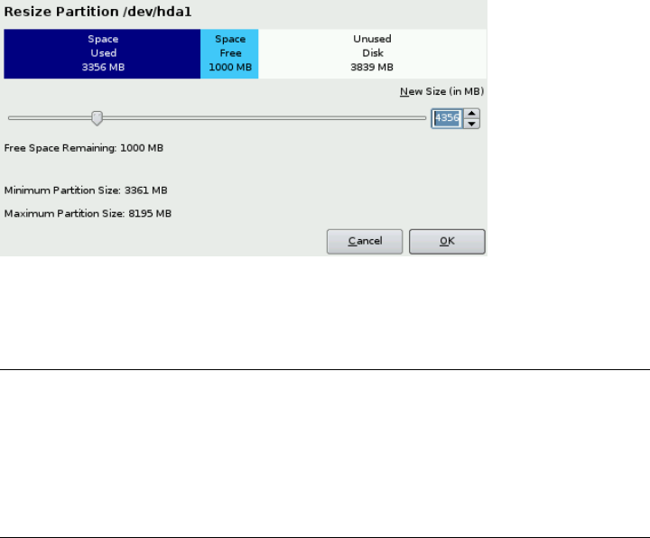
Figure 1.7 Resizing the Windows Partition
If you leave this dialog by selecting Next, the settings are stored and you are returned
to the previous dialog. The actual resizing takes place later, before the hard disk is for-
matted.
IMPORTANT: Writing on NTFS Partitions
By default, the Windows uses the NTFS le system. openSUSE includes read
and write access to the NTFS le system, but this feature has a few limitations.
This means that you cannot read or write encrypted or compressed les. Fur-
thermore, the Windows le permissions are not honored at the moment. See
http://en.opensuse.org/SDB:NTFS for more information.
1.10.2 Custom Partitioning
Set up your own partitioning scheme by selecting Create Partition Setup and then
Custom Partitioning. The Expert Partitioner opens, displaying the current partition
setup. Expand the Hard Disks in the System View pane by clicking on the +, then click
on one of the listed hard disks. Now you can Add,Edit,Resize, or Delete partitions.
For more information about custom partitioning and conguring advanced features,
refer to Section 3.1, “Using the YaST Partitioner” (page 73)
20 Reference

1.11 Create New User
Create a local user in this step. Administrating local users is a suitable option for stand-
alone workstations. If setting up a client on a network with centralized user authentica-
tion, click Change and proceed with the Section 1.11.1, “Expert Settings” (page 23).
After entering the rst name and last name, either accept the proposal or specify a new
Username that will be used to log in. Finally, enter a password for the user. Reenter it
for conrmation (to ensure that you did not type something else by mistake). To provide
effective security, a password should be between ve and eight characters long. The
maximum length for a password is 72 characters. However, if no special security
modules are loaded, only the rst eight characters are used to discern the password.
Passwords are case-sensitive. Special characters (7-bit ASCII) and the digits 0 to 9 are
allowed. Other special characters like umlauts or accented characters are not allowed.
Passwords you enter are checked for weakness. When entering a password that is easy
to guess (such as a dictionary word or a name) you will see a warning. It is a good se-
curity practice to use strong passwords.
IMPORTANT: Username and Password
Remember both your username and the password because they are needed
each time you log in to the system.
Installation with YaST 21

Figure 1.8 Create New User
Three additional options are available:
Use this Password for the System Administrator
If checked, the same password you have entered for the user will be used for the
system administrator root. This option is suitable for stand-alone workstations
or machines in a home network that are administrated by a single user. When not
checked, you are prompted for a system administrator password in the next step of
the installation workow (see Section 1.11.2, “Password for the System Adminis-
trator root” (page 24)).
Receive System Mail
Checking this box sends messages created by the system services to the user. These
are usually only sent to root, the system administrator. This option is useful for
the most frequently used account, because it is highly recommended to log in as
root only in special cases.
The mails sent by system services are stored in the local mailbox /var/spool/
mail/username, where username is the login name of the selected user. To
read e-mails after installation, you can use any e-mail client, for example KMail
or Evolution.
22 Reference

Automatic Login
This option automatically logs the current user in to the system when it starts. This
is mainly useful if the computer is operated by only one user.
WARNING: Automatic Login
With the automatic login enabled, the system boots straight into your desktop
with no authentication at all. If you store sensitive data on your system, you
should not enable this option as long as the computer can also be accessed by
others.
1.11.1 Expert Settings
Click Change in the Create User dialog to set up network authentication or, if present,
import users from a previous installation. Also change the password encryption type
in this dialog.
You can also add additional user accounts or change the user authentication method in
the installed system. For detailed information about user management, see Chapter 10,
Managing Users with YaST (↑Start-Up).
The default authentication method is Local (/etc/passwd). If a former version of open-
SUSE or another system using /etc/passwd is detected, you may import local users.
To do so, check Read User Data from a Previous Installation and click Choose. In the
next dialog, select the users to import and nish with OK.
Access to the following network authentication services can be congured:
LDAP
Users are administered centrally on an LDAP server for all systems in the network.
More information is available in Section “Conguring an LDAP Client with YaST”
(Chapter 4, LDAP—A Directory Service, ↑Security Guide).
NIS
Users are administered centrally on an NIS server for all systems in the network.
See Section “Conguring NIS Clients” (Chapter 3, Using NIS, ↑Security Guide)
for more information.
Installation with YaST 23

Windows Domain
SMB authentication is often used in mixed Linux and Windows networks. and
Section “Conguring a Linux Client for Active Directory” (Chapter 5, Active Di-
rectory Support, ↑Security Guide).
Along with user administration via LDAP and NIS, you can use Kerberos authentication.
To use it, select Set Up Kerberos Authentication. For more information on Kerberos,
refer to Chapter 6, Network Authentication with Kerberos (↑Security Guide).
1.11.2 Password for the System
Administrator root
If you have not chosen Use this Password for the System Administrator in the previous
step, you will be prompted to enter a Password for the System Administrator root.
Otherwise this conguration step is skipped.
root is the name of the superuser, or the administrator of the system. Unlike regular
users (who may or may not have permission to access certain areas or execute certain
commands on the system), root has unlimited access to change the system congura-
tion, install programs, and set up new hardware. If users forget their passwords or have
other problems with the system, root can help. The root account should only be
used for system administration, maintenance, and repair. Logging in as root for daily
work is rather risky: a single mistake could lead to irretrievable loss of system les.
For verication purposes, the password for root must be entered twice. Do not forget
the root password. Once entered, this password cannot be retrieved.
The root can be changed any time later in the installed system. To do so run YaST
and start Security and Users >User and Group Management.
WARNING: The root User
The user root has all the permissions needed to make changes to the system.
To carry out such tasks, the root password is required. You cannot carry out
any administrative tasks without this password.
24 Reference
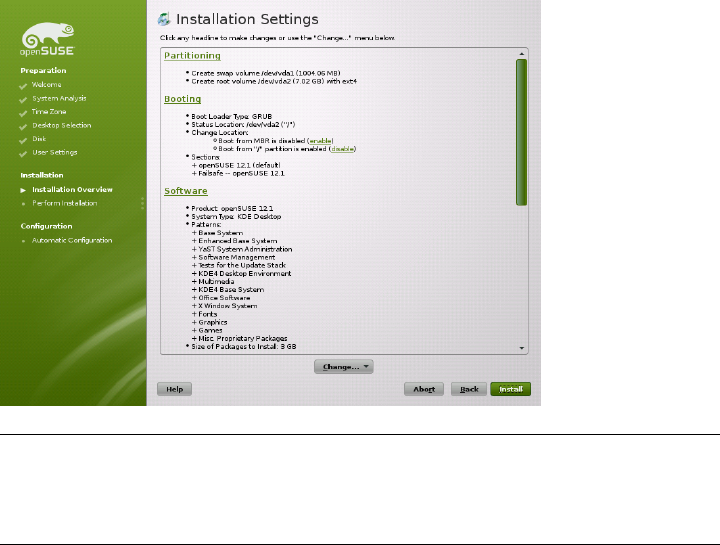
1.12 Installation Settings
On the last step before the real installation takes place, you can alter installation settings
suggested by YaST and also review the settings you made so far. To modify the sugges-
tions, either click Change and select the category to change or click on one of the
headlines. After conguring any of the items presented in these dialogs, you are always
returned to the Installation Settings window, which is updated accordingly.
Figure 1.9 Installation Settings
TIP: Restoring the Default Settings
You can reset all changes to the defaults by clicking Change >Reset to Defaults.
YaST then shows the original proposal again.
1.12.1 Partitioning
Review and, if necessary, change the partition setup you congured earlier. Modifying
the partition setup opens the Expert Partitioner described in Section 3.1, “Using the
YaST Partitioner” (page 73).
Installation with YaST 25
1.12.2 Booting
YaST proposes a boot conguration for your system. Other operating systems found
on your computer, such as Microsoft Windows or other Linux installations, will auto-
matically be detected and added to the boot loader. However, openSUSE will be booted
by default. Normally, you can leave these settings unchanged. If you need a custom
setup, modify the proposal for your system. For information, see Section 6.2, “Cong-
uring the Boot Loader with YaST” (page 110). The boot method should only be changed
by experienced users.
1.12.3 Software
openSUSE contains a number of software patterns for various application purposes.
Click Software to start the pattern selection and modify the installation scope according
to your needs. Select your pattern from the list and see a pattern description in the right
part of the window. Each pattern contains a number of software packages needed for
specic functions (e.g. Multimedia or Ofce software). For a more detailed selection
based on software packages to install, select Details to switch to the YaST Software
Manager.
You can also install additional software packages or remove software packages from
your system at any later time with the YaST Software Manager. For more information,
refer to Chapter 5, Installing or Removing Software (↑Start-Up).
26 Reference

Figure 1.10 Software Selection and System Tasks
1.12.4 Locale Settings
Here you can change the system Language and Keyboard Layout you dened in the
rst step of the installation. It is also possible to add additional languages. To adjust
the system language settings, select Language. Select a language from the list. The
primary language is used as the system language. You can also adapt keyboard layout
and time zone to the primary language if the current settings differ. Details lets you
modify language settings for the user root, set UTF-8 support, or further specify the
language (e.g. select South African English).
Choose secondary languages to be able to switch to one of these languages at any time
without having to install additional packages. For more information, see Chapter 11,
Changing Language and Country Settings with YaST (↑Start-Up).
To change the keyboard layout, select Keyboard Layout. By default, the layout corre-
sponds to the language chosen for installation. Select the keyboard layout from the list.
Use the Test eld at the bottom of the dialog to check if you can enter special characters
of that layout correctly. Options to ne-tune various settings are available under Expert
Mode. When nished, click Accept to return to the installation summary.
Installation with YaST 27
1.12.5 Time Zone
Adjust time zone and clock settings here. Provided a network is congured, you can
also set up a Network Time Protocol (NTP) client that automatically synchronizes your
computer with a time server. This is the same conguration as shown earlier in Sec-
tion 1.8, “Clock and Time Zone” (page 16).
1.12.6 User Settings
Change the current User settings and change or set the Root Password here. This is the
same conguration as shown earlier in Section 1.11, “Create New User” (page 21).
1.12.7 Default Runlevel
openSUSE can boot to different runlevels. Normally, there should be no need to change
anything here, but if necessary set the default runlevel with this dialog.
1.12.8 System
This dialog presents all the hardware information YaST could obtain about your com-
puter. When called, the hardware detection routine is started. Depending on your system,
this may take some time. Select any item in the list and click Details to see detailed
information about the selected item. Use Save to File to save a detailed list to either the
local le system or a oppy. Advanced users can also change the PCI ID setup and
Kernel Settings by choosing Kernel Settings.
1.12.9 Installation from Images
Installing from images considerably speeds up the installation. Images contain com-
pressed snapshots of installed systems matching your selection of patterns. Packages
not contained in the images deployed will be installed conventionally.
Unless your custom software selection does not match any of the available images, this
feature is Enabled by default. In case of problems, Disable it for debugging purposes.
28 Reference

1.12.10 Firewall
By default SuSEFirewall2 is enabled on all congured network interfaces. To globally
disable the rewall for this computer, click on Disable. If the rewall is enabled, you
may Open the SSH port in order to allow remote connections via secure shell.
1.13 Performing the Installation
After conguring all installation settings, click Install in the Installation Settings window
to start the installation. Some software may require a license conrmation. If your
software selection includes such software, license conrmation dialogs are displayed.
Click Accept to install the software package. When not agreeing to the license, click I
Disagree and the software package will not be installed. In the dialog that follows,
conrm with Install again.
The installation usually takes between 15 and 30 minutes, depending on the system
performance and the selected software scope. After having prepared the hard disk,
having saved and restored the user settings, and having deployed the installation images,
the software installation starts. During this procedure a slide show introduces the features
of openSUSE. Choose Details to switch to the installation log or Release Notes to read
important up-to-date information which was not available when the manuals were
printed.
NOTE: Release Notes
The release notes that can be viewed during this step are the ones printed on
the installation CD. A newer version may be available on the Internet. When
manually conguring network and Internet access, the latest version of the
release notes will be displayed at the end of the installation.
After the software installation has completed, the basic system is set up. Among others,
“Finishing the Basic Installation” includes installing the boot manager, initializing fonts
and more. Next YaST boots into the new Linux system to start the system conguration.
Installation with YaST 29

TIP: Existing SSH Host Keys
If you install openSUSE on a machine with existing Linux installations, the instal-
lation routine automatically imports the SSH host key with the most recent
access time from an existing installation.
1.14 Conguration of the Installed
System
The system is now installed, but not yet congured for use. The hardware, the network
and other services are not yet set up. If you follow the default installation path, the
system will be automatically congured. If you have deselected the Automatic Con-
guration, the manual system conguration starts.
1.14.1 Automatic System Conguration
Having rebooted, the system starts the Automatic Conguration. This routine attempts
to congure your network and Internet access and sets up your hardware. This process
does not need any interaction. You can change the settings made by Automatic Con-
guration at any time on the installed system with YaST. Continue with Section 1.15,
“Graphical Login” (page 35).
1.14.2 Manual System Conguration
Having rebooted, the system starts the manual conguration. If the conguration fails
at one of the steps of this stage, it restarts and continues from the last successful step.
1.14.2.1 Hostname and Domain Name
The hostname is the computer's name in the network. The domain name is the name of
the network. A hostname and domain are proposed by default. If your system is part
of a network, the hostname has to be unique in this network, whereas the domain name
has to be common to all hosts on the network.
30 Reference
In many networks, the system receives its name over DHCP. In this case it is not nec-
essary to modify the proposed hostname and domain name. Select Change Hostname
via DHCP instead. To be able to access your system using this hostname, even when
it is not connected to the network, select Assign Hostname to Loopback IP. Do n ot
enable this option when your machine provides network services. If you often change
networks without restarting the desktop environment (e.g. when switching between
different WLANs), do not enable this option either, because the desktop system may
get confused when the hostname in /etc/hosts changes.
To change hostname settings at any time after installation, use YaST Network Devices
>Network Settings. For more information, see Section 9.4.1, “Conguring the Network
Card with YaST” (page 169).
1.14.2.2 Network Conguration
If you are installing openSUSE on a laptop computer, Interfaces Controlled by Network-
Manager is enabled. NetworkManager is a tool that enables automatic connection with
minimal user intervention. It is ideal for WLAN and mobile computing. If you want to
use the traditional method without NetworkManager, click Disable NetworkManager.
Find detailed information about NetworkManager in Chapter 21, Using NetworkMan-
ager (page 379). If you are installing openSUSE on any other type of machine, the tra-
ditional method without NetworkManager is selected by default. This conguration
step also lets you congure the network devices of your system and make security set-
tings, for example, for a rewall or proxy.
The network can also be congured after the system installation has been completed.
If you skip it now, your system is left ofine unable to retrieve any available updates.
To congure your network connection later, select Skip Conguration and click Next.
The following network settings can be congured in this step:
General Network Settings
Enable or disable the use of NetworkManager as described above. Also change the
IPv6 support here. By default the IPv6 support is enabled. To disable it, click Dis-
able IPv6. For more information about IPv6, see Section 9.2, “IPv6—The Next
Generation Internet” (page 157).
Firewall
By default SuSEFirewall2 is enabled on all congured network interfaces. To
globally disable the rewall for this computer, click on Disable. If the rewall is
Installation with YaST 31

enabled, you may Open the SSH port in order to allow remote connections via secure
shell. To open the detailed rewall conguration dialog, click on Firewall. See
Section “Conguring the Firewall with YaST” (Chapter 13, Masquerading and
Firewalls, ↑Security Guide) for detailed information.
Network Interfaces
All network cards detected by YaST are listed here. If you have already set up a
network connection during the installation (as described in Section 1.7.1.1, “Network
Setup” (page 15)) the card used for this connection is listed as Congured. A click
on Network Interfaces opens the Network Settings dialog, where you can change
existing congurations, set up networks cards not congured yet, or add and con-
gure additional cards.
DSL Connections,ISDN Adapters, and Modems
If your computer is equipped with an internal DSL modem, an internal ADSL Fritz
Card, an ISDN card or a modem, clicking on the respective headline opens the
conguration dialog.
VNC Remote Administration
To enable remote administration of your machine via VNC, click VNC Remote
Administration. Choose Allow Remote Administration in the following dialog and
adjust your rewall settings accordingly.
Proxy
If you have a proxy server controlling the Internet access in your network, congure
the proxy URLs and authentication details in this dialog.
TIP: Resetting the Network Conguration to the Default Values
Reset the network settings to the original proposed values by clicking Change
>Reset to Defaults. This discards any changes made.
Test Internet Connection
After having congured a network connection, you can test it. For this purpose, YaST
establishes a connection to the openSUSE server and downloads the latest release notes.
Read them at the end of the installation process. A successful test is also a prerequisite
for the automatic addition of the default repositories and for updating online.
32 Reference

If you have multiple network interfaces, verify that the desired card is used to connect
to the Internet. If not, click Change Device.
To start the test, select Yes, Test Connection to the Internet and click Next. In the fol-
lowing dialog, view the progress of the test and the results. Detailed information about
the test process is available via View Logs. If the test fails, click Back to return to the
network conguration to correct your entries.
Proceed with Next. If the test was successful, the ofcial software repositories for
openSUSE and the update repository will be congured. Downloading the repository
data for the rst time may take some time.
If you do not want to test the connection at this point, select No, Skip This Test then
Next. This also skips downloading the release notes, and updating online. These steps
can be performed any time after the system has been initially congured.
1.14.2.3 Online Update
If an Internet connection has been established, and updates are available, select whether
to perform a YaST online update. If there are any patched packages available on the
servers, download and install them now to x known bugs or security issues. For detailed
instructions see Chapter 6, YaST Online Update (↑Start-Up). Directives on how to
perform an online update in the installed system are available at Section “Keeping the
System Up-to-date” (Chapter 5, Installing or Removing Software, ↑Start-Up) or Chap-
ter 6, YaST Online Update (↑Start-Up). This step is skipped if no updates are available
or no Internet connection has been established. Patches xing security issues and rec-
ommended patches applying to your installation are automatically preselected. Click
Accept to install them and Next to proceed with the system conguration.
IMPORTANT: Downloading Software Updates
The download of updates might take quite some time, depending on the
bandwidth of the Internet connection and the size of the update les. In case
the patch system itself is updated, the online update will restart and download
more patches after the restart. If the kernel was updated, the system will reboot
before completing the conguration.
Installation with YaST 33

1.14.2.4 New Local User
If no local user was created in step one, you can create one in this dialog. To create
more users, manage groups, modify defaults for new users and set up network authen-
tication, launch User Management. Refer to Chapter 10, Managing Users with YaST
(↑Start-Up) for more information about user management. To skip this step, click Next
without entering any data.
1.14.2.5 Release Notes
After completing the user authentication setup, YaST displays the release notes. Reading
them is recommended, because they contain important up-to-date information which
was not available when the manuals were printed. If you successfully tested the Internet
connection, read the most recent version of the release notes, as fetched from openSUSE's
servers. Use Miscellaneous >Release Notes in YaST or start the SUSE Help Center to
view the release notes after installation.
1.14.2.6 Hardware Conguration
At the end of the installation, YaST opens a dialog for the conguration of Graphics
Cards Printer . Click the individual components to start the hardware conguration.
For the most part, YaST detects and congures the devices automatically.
You can skip any peripheral devices and congure them later, as described in Chapter 13,
Setting Up Hardware Components with YaST (↑Start-Up). To skip the conguration,
select Skip Conguration and click Next.
TIP: Resetting Hardware Conguration to the Default Values
You can cancel any changes to the hardware conguration by clicking Change
>Reset to Defaults. YaST then shows the original proposal again.
1.14.2.7 Installation Completed
After a successful installation, YaST shows the Installation Completed dialog. In this
dialog, select whether to clone your newly installed system for AutoYaST. To clone
your system, select Clone This System for AutoYaST. The prole of the current system
is stored in /root/autoyast.xml.
34 Reference
AutoYaST is a system for installing one or more openSUSE systems automatically
without user intervention. AutoYaST installations are performed using a control le
with installation and conguration data. Finish the installation of openSUSE with Finish
in the nal dialog.
1.15 Graphical Login
openSUSE is now fully installed and congured. Unless you enabled the automatic
login function or customized the default runlevel, you should see the graphical login
on your screen in which to enter a username and password to log into the system. On
single user systems with automatic login enabled, the desktop starts automatically.
For a short introduction to the KDE or GNOME desktop environments, refer to the
Chapter 3, GNOME Quick Start (↑Start-Up) and the Chapter 2, KDE Quick Start (↑Start-
Up). These manuals can be accessed via the Help function in both KDE and GNOME.
Installation with YaST 35

2
Remote Installation
openSUSE® can be installed in different ways. As well as the usual media installation
covered in Chapter 1, Installation with YaST (page 3), you can choose from various
network-based approaches or even take a completely hands-off approach to the instal-
lation of openSUSE.
Each method is introduced by means of two short check lists: one listing the prerequisites
for this method and the other illustrating the basic procedure. More detail is then pro-
vided for all the techniques used in these installation scenarios.
NOTE
In the following sections, the system to hold your new openSUSE installation
is referred to as target system or installation target. The term repository (pre-
viously called “installation source”) is used for all sources of installation data.
This includes physical media, such as CD and DVD, and network servers dis-
tributing the installation data in your network.
2.1 Installation Scenarios for Remote
Installation
This section introduces the most common installation scenarios for remote installations.
For each scenario, carefully check the list of prerequisites and follow the procedure
outlined for this scenario. If in need of detailed instructions for a particular step, follow
the links provided for each one of them.
Remote Installation 37
2.1.1 Simple Remote Installation via
VNC—Static Network Conguration
This type of installation still requires some degree of physical access to the target system
to boot for installation. The installation itself is entirely controlled by a remote worksta-
tion using VNC to connect to the installation program. User interaction is required as
with the manual installation in Chapter 1, Installation with YaST (page 3).
For this type of installation, make sure that the following requirements are met:
• Remote repository: NFS, HTTP, FTP, or SMB with working network connection.
• Target system with working network connection.
• Controlling system with working network connection and VNC viewer software or
Java-enabled browser (Firefox, Konqueror, Internet Explorer, Opera, etc.).
• Physical boot medium (CD, DVD, or USB ash drive) for booting the target system.
•Valid static IP addresses already assigned to the repository and the controlling system.
• Valid static IP address to assign to the target system.
To perform this kind of installation, proceed as follows:
1Set up the repository as described in Section 2.2, “Setting Up the Server Holding
the Installation Sources” (page 46). Choose an NFS, HTTP, or FTP network server.
For an SMB repository, refer to Section 2.2.5, “Managing an SMB Repository”
(page 53).
2Boot the target system using a boot medium (DVD, CD, or USB ash drive) of the
openSUSE media kit. For more information about the openSUSE media kit, see
Section 1.1, “Choosing the Installation Media” (page 3).
3When the boot screen of the target system appears, use the boot options prompt to
set the appropriate VNC options and the address of the repository. This is described
in detail in Section 2.4, “Booting the Target System for Installation” (page 65).
The target system boots to a text-based environment, giving the network address
and display number under which the graphical installation environment can be ad-
38 Reference
dressed by any VNC viewer application or browser. VNC installations announce
themselves over OpenSLP and if the rewall settings permit, they can be found using
Konqueror in service:/ or slp:/ mode.
4On the controlling workstation, open a VNC viewing application or Web browser
and connect to the target system as described in Section 2.5.1, “VNC Installation”
(page 69).
5Perform the installation as described in Chapter 1, Installation with YaST (page 3).
Reconnect to the target system after it reboots for the nal part of the installation.
6Finish the installation.
2.1.2 Simple Remote Installation via
VNC—Dynamic Network Conguration
This type of installation still requires some degree of physical access to the target system
to boot for installation. The network conguration is made with DHCP. The installation
itself is entirely controlled from a remote workstation using VNC to connect to the in-
staller, but still requires user interaction for the actual conguration efforts.
For this type of installation, make sure that the following requirements are met:
• Remote repository: NFS, HTTP, FTP, or SMB with working network connection.
• Target system with working network connection.
• Controlling system with working network connection and VNC viewer software or
Java-enabled browser (Firefox, Konqueror, Internet Explorer, or Opera).
• Boot the target system using a boot medium (DVD, CD, or USB ash drive) of the
openSUSE media kit. For more information about the openSUSE media kit, see
Section 1.1, “Choosing the Installation Media” (page 3).
• Running DHCP server providing IP addresses.
To perform this kind of installation, proceed as follows:
Remote Installation 39
1Set up the repository as described in Section 2.2, “Setting Up the Server Holding
the Installation Sources” (page 46). Choose an NFS, HTTP, or FTP network server.
For an SMB repository, refer to Section 2.2.5, “Managing an SMB Repository”
(page 53).
2Boot the target system using a boot medium (DVD, CD, or USB ash drive) of the
openSUSE media kit. For more information about the openSUSE media kit, see
Section 1.1, “Choosing the Installation Media” (page 3).
3When the boot screen of the target system appears, use the boot options prompt to
set the appropriate VNC options and the address of the repository. This is described
in detail in Section 2.4, “Booting the Target System for Installation” (page 65).
The target system boots to a text-based environment, giving the network address
and display number under which the graphical installation environment can be ad-
dressed by any VNC viewer application or browser. VNC installations announce
themselves over OpenSLP and if the rewall settings permit, they can be found using
Konqueror in service:/ or slp:/ mode.
4On the controlling workstation, open a VNC viewing application or Web browser
and connect to the target system as described in Section 2.5.1, “VNC Installation”
(page 69).
5Perform the installation as described in Chapter 1, Installation with YaST (page 3).
Reconnect to the target system after it reboots for the nal part of the installation.
6Finish the installation.
2.1.3 Remote Installation via VNC—PXE
Boot and Wake on LAN
This type of installation is completely hands-off. The target machine is started and
booted remotely. User interaction is only needed for the actual installation. This approach
is suitable for cross-site deployments.
To perform this type of installation, make sure that the following requirements are met:
• Remote repository: NFS, HTTP, FTP, or SMB with working network connection.
40 Reference
• TFTP server.
• Running DHCP server for your network.
• Target system capable of PXE boot, networking, and Wake on LAN, plugged in and
connected to the network.
• Controlling system with working network connection and VNC viewer software or
Java-enabled browser (Firefox, Konqueror, Internet Explorer, or Opera).
To perform this type of installation, proceed as follows:
1Set up the repository as described in Section 2.2, “Setting Up the Server Holding
the Installation Sources” (page 46). Choose an NFS, HTTP, or FTP network server
or congure an SMB repository as described in Section 2.2.5, “Managing an SMB
Repository” (page 53).
2Set up a TFTP server to hold a boot image that can be pulled by the target system.
This is described in Section 2.3.2, “Setting Up a TFTP Server” (page 58).
3Set up a DHCP server to provide IP addresses to all machines and reveal the location
of the TFTP server to the target system. This is described in Section 2.3.1, “Setting
Up a DHCP Server” (page 55).
4Prepare the target system for PXE boot. This is described in further detail in Sec-
tion 2.3.5, “Preparing the Target System for PXE Boot” (page 64).
5Initiate the boot process of the target system using Wake on LAN. This is described
in Section 2.3.7, “Wake on LAN” (page 65).
6On the controlling workstation, open a VNC viewing application or Web browser
and connect to the target system as described in Section 2.5.1, “VNC Installation”
(page 69).
7Perform the installation as described in Chapter 1, Installation with YaST (page 3).
Reconnect to the target system after it reboots for the nal part of the installation.
8Finish the installation.
Remote Installation 41
2.1.4 Simple Remote Installation via
SSH—Static Network Conguration
This type of installation still requires some degree of physical access to the target system
to boot for installation and to determine the IP address of the installation target. The
installation itself is entirely controlled from a remote workstation using SSH to connect
to the installer. User interaction is required as with the regular installation described in
Chapter 1, Installation with YaST (page 3).
For this type of installation, make sure that the following requirements are met:
• Remote repository: NFS, HTTP, FTP, or SMB with working network connection.
• Target system with working network connection.
• Controlling system with working network connection and working SSH client soft-
ware.
• Boot the target system using a boot medium (DVD, CD, or USB ash drive) of the
openSUSE media kit. For more information about the openSUSE media kit, see
Section 1.1, “Choosing the Installation Media” (page 3).
•Valid static IP addresses already assigned to the repository and the controlling system.
• Valid static IP address to assign to the target system.
To perform this kind of installation, proceed as follows:
1Set up the repository as described in Section 2.2, “Setting Up the Server Holding
the Installation Sources” (page 46). Choose an NFS, HTTP, or FTP network server.
For an SMB repository, refer to Section 2.2.5, “Managing an SMB Repository”
(page 53).
2Boot the target system using a boot medium (DVD, CD, or USB ash drive) of the
openSUSE media kit. For more information about the openSUSE media kit, see
Section 1.1, “Choosing the Installation Media” (page 3).
3When the boot screen of the target system appears, use the boot options prompt to
set the appropriate parameters for network connection, address of the repository,
42 Reference
and SSH enablement. This is described in detail in Section 2.4.2, “Using Custom
Boot Options” (page 66).
The target system boots to a text-based environment, giving the network address
under which the graphical installation environment can be addressed by any SSH
client.
4On the controlling workstation, open a terminal window and connect to the target
system as described in Section 2.5.2.2, “Connecting to the Installation Program”
(page 71).
5Perform the installation as described in Chapter 1, Installation with YaST (page 3).
Reconnect to the target system after it reboots for the nal part of the installation.
6Finish the installation.
2.1.5 Simple Remote Installation via
SSH—Dynamic Network Conguration
This type of installation still requires some degree of physical access to the target system
to boot for installation and determine the IP address of the installation target. The instal-
lation itself is entirely controlled from a remote workstation using VNC to connect to
the installer, but still requires user interaction for the actual conguration efforts.
For this type of installation, make sure that the following requirements are met:
• Remote repository: NFS, HTTP, FTP, or SMB with working network connection.
• Target system with working network connection.
• Controlling system with working network connection and working SSH client soft-
ware.
• Physical boot medium (CD, DVD, or USB ash drive) for booting the target system.
• Running DHCP server providing IP addresses.
To perform this kind of installation, proceed as follows:
Remote Installation 43
1Set up the repository source as described in Section 2.2, “Setting Up the Server
Holding the Installation Sources” (page 46). Choose an NFS, HTTP, or FTP network
server. For an SMB repository, refer to Section 2.2.5, “Managing an SMB Repository”
(page 53).
2Boot the target system using a boot medium (DVD, CD, or USB ash drive) of the
openSUSE media kit. For more information about the openSUSE media kit, see
Section 1.1, “Choosing the Installation Media” (page 3).
3When the boot screen of the target system appears, use the boot options prompt to
pass the appropriate parameters for network connection, location of the installation
source, and SSH enablement. See Section 2.4.2, “Using Custom Boot Options”
(page 66) for detailed instructions on the use of these parameters.
The target system boots to a text-based environment, giving you the network address
under which the graphical installation environment can be addressed by any SSH
client.
4On the controlling workstation, open a terminal window and connect to the target
system as described in Section 2.5.2.2, “Connecting to the Installation Program”
(page 71).
5Perform the installation as described in Chapter 1, Installation with YaST (page 3).
Reconnect to the target system after it reboots for the nal part of the installation.
6Finish the installation.
2.1.6 Remote Installation via SSH—PXE Boot
and Wake on LAN
This type of installation is completely hands-off. The target machine is started and
booted remotely.
To perform this type of installation, make sure that the following requirements are met:
• Remote repository: NFS, HTTP, FTP, or SMB with working network connection.
• TFTP server.
44 Reference
• Running DHCP server for your network, providing a static IP to the host to install.
• Target system capable of PXE boot, networking, and Wake on LAN, plugged in and
connected to the network.
• Controlling system with working network connection and SSH client software.
To perform this type of installation, proceed as follows:
1Set up the repository as described in Section 2.2, “Setting Up the Server Holding
the Installation Sources” (page 46). Choose an NFS, HTTP, or FTP network server.
For the conguration of an SMB repository, refer to Section 2.2.5, “Managing an
SMB Repository” (page 53).
2Set up a TFTP server to hold a boot image that can be pulled by the target system.
This is described in Section 2.3.2, “Setting Up a TFTP Server” (page 58).
3Set up a DHCP server to provide IP addresses to all machines and reveal the location
of the TFTP server to the target system. This is described in Section 2.3.1, “Setting
Up a DHCP Server” (page 55).
4Prepare the target system for PXE boot. This is described in further detail in Sec-
tion 2.3.5, “Preparing the Target System for PXE Boot” (page 64).
5Initiate the boot process of the target system using Wake on LAN. This is described
in Section 2.3.7, “Wake on LAN” (page 65).
6On the controlling workstation, start an SSH client and connect to the target system
as described in Section 2.5.2, “SSH Installation” (page 70).
7Perform the installation as described in Chapter 1, Installation with YaST (page 3).
Reconnect to the target system after it reboots for the nal part of the installation.
8Finish the installation.
Remote Installation 45

2.2 Setting Up the Server Holding the
Installation Sources
Depending on the operating system running on the machine to use as the network instal-
lation source for openSUSE, there are several options for the server conguration. The
easiest way to set up an installation server is to use YaST on openSUSE 11.1 and
higher.
TIP
You can even use a Microsoft Windows machine as the installation server for
your Linux deployment. See Section 2.2.5, “Managing an SMB Repository”
(page 53) for details.
2.2.1 Setting Up an Installation Server Using
YaST
YaST offers a graphical tool for creating network repositories. It supports HTTP, FTP,
and NFS network installation servers.
1Log in as root to the machine that should act as installation server.
2Install the yast2-instserver package.
3Start YaST >Miscellaneous >Installation Server.
4Select the repository type (HTTP, FTP, or NFS). The selected service is started au-
tomatically every time the system starts. If a service of the selected type is already
running on your system and you want to congure it manually for the server, deac-
tivate the automatic conguration of the server service with Do Not Congure Any
Network Services. In both cases, dene the directory in which the installation data
should be made available on the server.
5Congure the required repository type. This step relates to the automatic conguration
of server services. It is skipped when automatic conguration is deactivated.
46 Reference

Dene an alias for the root directory of the FTP or HTTP server on which the instal-
lation data should be found. The repository will later be located under
ftp://Server-IP/Alias/Name (FTP) or under
http://Server-IP/Alias/Name (HTTP). Name stands for the name of the
repository, which is dened in the following step. If you selected NFS in the previous
step, dene wild cards and export options. The NFS server will be accessible under
nfs://Server-IP/Name. Details of NFS and exports can be found in Chapter 14,
Sharing File Systems with NFS (page 259).
TIP: Firewall Settings
Make sure that the rewall settings of your server system allow trafc on
the ports for HTTP, NFS, and FTP. If they currently do not, enable Open Port
in Firewall or check Firewall Details rst.
6Congure the repository. Before the installation media are copied to their destination,
dene the name of the repository (ideally, an easily remembered abbreviation of the
product and version). YaST allows providing ISO images of the media instead of
copies of the installation DVDs. If you want this, activate the relevant check box
and specify the directory path under which the ISO les can be found locally. De-
pending on the product to distribute using this installation server, it might be that
more add-on CDs or service pack CDs are required and should be added as extra
repositories. To announce your installation server in the network via OpenSLP, acti-
vate the appropriate option.
TIP
Consider announcing your repository via OpenSLP if your network setup
supports this option. This saves you from entering the network installation
path on every target machine. The target systems are just booted using the
SLP boot option and nd the network repository without any further con-
guration. For details on this option, refer to Section 2.4, “Booting the Target
System for Installation” (page 65).
7Upload the installation data. The most lengthy step in conguring an installation
server is copying the actual installation media. Insert the media in the sequence re-
quested by YaST and wait for the copying procedure to end. When the sources have
been fully copied, return to the overview of existing repositories and close the con-
guration by selecting Finish.
Remote Installation 47
Your installation server is now fully congured and ready for service. It is automat-
ically started every time the system is started. No further intervention is required.
You only need to congure and start this service correctly by hand if you have deac-
tivated the automatic conguration of the selected network service with YaST as an
initial step.
To deactivate a repository, select the repository to remove then select Delete. The in-
stallation data are removed from the system. To deactivate the network service, use the
respective YaST module.
If your installation server needs to provide the installation data for more than one
product of the product version, start the YaST installation server module and select Add
in the overview of existing repositories to congure the new repository.
2.2.2 Setting Up an NFS Repository
Manually
Setting up an NFS source for installation is basically done in two steps. In the rst step,
create the directory structure holding the installation data and copy the installation
media over to this structure. Second, export the directory holding the installation data
to the network.
To create a directory to hold the installation data, proceed as follows:
1Log in as root.
2Create a directory that will later hold all installation data and change into this direc-
tory. For example:
mkdir install/product/productversion
cd install/product/productversion
Replace product with an abbreviation of the product name and productversion
with a string that contains the product name and version.
3For each DVD contained in the media kit execute the following commands:
3a Copy the entire content of the installation DVD into the installation server
directory:
48 Reference
cp -a /media/path_to_your_DVD_drive .
Replace path_to_your_DVD_drive with the actual path under which
your DVD drive is addressed. Depending on the type of drive used in your
system, this can be cdrom,cdrecorder,dvd, or dvdrecorder.
3b Rename the directory to the DVD number:
mv path_to_your_DVD_drive DVDx
Replace xwith the actual number of your DVD.
On openSUSE, you can export the repository with NFS using YaST. Proceed as follows:
1Log in as root.
2Start YaST >Network Services >NFS Server.
3Select Start and Open Port in Firewall and click Next.
4Select Add Directory and browse for the directory containing the installation sources,
in this case, productversion.
5Select Add Host and enter the hostnames of the machines to which to export the in-
stallation data. Instead of specifying hostnames here, you could also use wild cards,
ranges of network addresses, or just the domain name of your network. Enter the
appropriate export options or leave the default, which works ne in most setups. For
more information about the syntax used in exporting NFS shares, read the exports
man page.
6Click Finish. The NFS server holding the openSUSE repository is automatically
started and integrated into the boot process.
If you prefer manually exporting the repository via NFS instead of using the YaST NFS
Server module, proceed as follows:
1Log in as root.
2Open the le /etc/exports and enter the following line:
/productversion *(ro,root_squash,sync)
Remote Installation 49
This exports the directory /productversion to any host that is part of this net-
work or to any host that can connect to this server. To limit the access to this server,
use netmasks or domain names instead of the general wild card *. Refer to the
export man page for details. Save and exit this conguration le.
3To add the NFS service to the list of servers started during system boot, execute the
following commands:
insserv /etc/init.d/nfsserver
4Start the NFS server with rcnfsserver start. If you need to change the con-
guration of your NFS server later, modify the conguration le and restart the NFS
daemon with rcnfsserver restart.
Announcing the NFS server via OpenSLP makes its address known to all clients in
your network.
1Log in as root.
2Create the /etc/slp.reg.d/install.suse.nfs.reg conguration le
with the following lines:
# Register the NFS Installation Server
service:install.suse:nfs://$HOSTNAME/path_to_repository/DVD1,en,65535
description=NFS Repository
Replace path_to_repository with the actual path to the installation source
on your server.
3Start the OpenSLP daemon with rcslpd start.
For more information about OpenSLP, refer to the package documentation located under
/usr/share/doc/packages/openslp/ or refer to Chapter 10, SLP Services
in the Network (page 211). More Information about NFS, refer to Chapter 14, Sharing
File Systems with NFS (page 259).
2.2.3 Setting Up an FTP Repository Manually
Creating an FTP repository is very similar to creating an NFS repository. An FTP
repository can be announced over the network using OpenSLP as well.
50 Reference
1Create a directory holding the installation sources as described in Section 2.2.2,
“Setting Up an NFS Repository Manually” (page 48).
2Congure the FTP server to distribute the contents of your installation directory:
2a Log in as root and install the package vsftpd using the YaST software
management.
2b Enter the FTP server root directory:
cd /srv/ftp
2c Create a subdirectory holding the installation sources in the FTP root directory:
mkdir repository
Replace repository with the product name.
2d Mount the contents of the installation repository into the change root environ-
ment of the FTP server:
mount --bind path_to_repository /srv/ftp/repository
Replace path_to_repository and repository with values matching
your setup. If you need to make this permanent, add it to /etc/fstab.
2e Start vsftpd with vsftpd.
3Announce the repository via OpenSLP, if this is supported by your network setup:
3a Create the /etc/slp.reg.d/install.suse.ftp.reg conguration
le with the following lines:
# Register the FTP Installation Server
service:install.suse:ftp://$HOSTNAME/repository/DVD1,en,65535
description=FTP Repository
Replace repository with the actual name to the repository directory on
your server. The service: line should be entered as one continuous line.
3b Start the OpenSLP daemon with rcslpd start.
Remote Installation 51

TIP: Conguring an FTP Server with YaST
If you prefer using YaST over manually conguring the FTP installation server,
refer to Chapter 17, Setting up an FTP server with YaST (page 331) for more in-
formation on how to use the YaST FTP server module.
2.2.4 Setting Up an HTTP Repository
Manually
Creating an HTTP repository is very similar to creating an NFS repository. An HTTP
repository can be announced over the network using OpenSLP as well.
1Create a directory holding the installation sources as described in Section 2.2.2,
“Setting Up an NFS Repository Manually” (page 48).
2Congure the HTTP server to distribute the contents of your installation directory:
2a Install the Web server Apache as described in Section 16.1.2, “Installation”
(page 288).
2b Enter the root directory of the HTTP server (/srv/www/htdocs) and
create the subdirectory that will hold the installation sources:
mkdir repository
Replace repository with the product name.
2c Create a symbolic link from the location of the installation sources to the root
directory of the Web server (/srv/www/htdocs):
ln -s /path_to_repository /srv/www/htdocs/repository
2d Modify the conguration le of the HTTP server (/etc/apache2/
default-server.conf) to make it follow symbolic links. Replace the
following line:
Options None
with
Options Indexes FollowSymLinks
52 Reference
2e Reload the HTTP server conguration using rcapache2 reload.
3Announce the repository via OpenSLP, if this is supported by your network setup:
3a Create the /etc/slp.reg.d/install.suse.http.reg conguration
le with the following lines:
# Register the HTTP Installation Server
service:install.suse:http://$HOSTNAME/repository/DVD1/,en,65535
description=HTTP Repository
Replace repository with the actual path to the repository on your server.
The service: line should be entered as one continuous line.
3b Start the OpenSLP daemon using rcslpd restart.
2.2.5 Managing an SMB Repository
Using SMB, you can import the installation sources from a Microsoft Windows server
and start your Linux deployment even with no Linux machine around.
To set up an exported Windows Share holding your openSUSE repository, proceed as
follows:
1Log in to your Windows machine.
2Create a new folder that will hold the entire installation tree and name it INSTALL,
for example.
3Export this share according the procedure outlined in your Windows documentation.
4Enter this share and create a subfolder, called product. Replace product with
the actual product name.
5Enter the INSTALL/product folder and copy each DVD to a separate folder,
such as DVD1 and DVD2.
To use a SMB mounted share as a repository, proceed as follows:
Remote Installation 53
1Boot the installation target.
2Select Installation.
3Press F4 for a selection of the repository.
4Choose SMB and enter the Windows machine's name or IP address, the share name
(INSTALL/product/DVD1, in this example), username, and password.
After you hit Enter, YaST starts and you can perform the installation.
2.2.6 Using ISO Images of the Installation
Media on the Server
Instead of copying physical media into your server directory manually, you can also
mount the ISO images of the installation media into your installation server and use
them as a repository. To set up an HTTP, NFS or FTP server that uses ISO images in-
stead of media copies, proceed as follows:
1Download the ISO images and save them to the machine to use as the installation
server.
2Log in as root.
3Choose and create an appropriate location for the installation data, as described in
Section 2.2.2, “Setting Up an NFS Repository Manually” (page 48), Section 2.2.3,
“Setting Up an FTP Repository Manually” (page 50), or Section 2.2.4, “Setting Up
an HTTP Repository Manually” (page 52).
4Create subdirectories for each DVD.
5To mount and unpack each ISO image to the nal location, issue the following
command:
mount -o loop path_to_isopath_to_repository/product/mediumx
Replace path_to_iso with the path to your local copy of the ISO image,
path_to_repository with the source directory of your server, product with
54 Reference
the product name, and mediumx with the type (CD or DVD) and number of media
you are using.
6Repeat the previous step to mount all ISO images needed for your product.
7Start your installation server as usual, as described in Section 2.2.2, “Setting Up an
NFS Repository Manually” (page 48), Section 2.2.3, “Setting Up an FTP Repository
Manually” (page 50), or Section 2.2.4, “Setting Up an HTTP Repository Manually”
(page 52).
To automatically mount the ISO images at boot time, add the respective mount entries
to /etc/fstab. An entry according to the previous example would look like the
following:
path_to_iso path_to_repository/productmedium auto loop
2.3 Preparing the Boot of the Target
System
This section covers the conguration tasks needed in complex boot scenarios. It contains
ready-to-apply conguration examples for DHCP, PXE boot, TFTP, and Wake on
LAN.
2.3.1 Setting Up a DHCP Server
There are two ways to set up a DHCP server. For openSUSE, YaST provides a graphical
interface to the process. Users can also manually edit the conguration les. For more
information about DHCP servers, see also Chapter 12, DHCP (page 241).
2.3.1.1 Setting Up a DHCP Server with YaST
To announce the TFTP server's location to the network clients and specify the boot
image le the installation target should use, add two declarations to your DHCP server
conguration.
Remote Installation 55
1Log in as root to the machine hosting the DHCP server.
2Install the yast2-dhcp-server package.
3Start YaST >Network Services >DHCP Server.
4Complete the setup wizard for basic DHCP server setup.
5Select Expert Settings and select Yes when warned about leaving the start-up dia-
log.
6In the Congured Declarations dialog, select the subnet in which the new system
should be located and click Edit.
7In the Subnet Conguration dialog select Add to add a new option to the subnet's
conguration.
8Select filename and enter pxelinux.0 as the value.
9Add another option (next-server) and set its value to the address of the TFTP
server.
10 Select OK and Finish to complete the DHCP server conguration.
To congure DHCP to provide a static IP address to a specic host, enter the Expert
Settings of the DHCP server conguration module (Step 5 (page 56)) and add a new
declaration of the host type. Add the options hardware and fixed-address to
this host declaration and provide the appropriate values.
2.3.1.2 Setting Up a DHCP Server Manually
All the DHCP server needs to do, apart from providing automatic address allocation to
your network clients, is to announce the IP address of the TFTP server and the le that
needs to be pulled in by the installation routines on the target machine.
1Log in as root to the machine hosting the DHCP server.
2Append the following lines to a subnet conguration of your DHCP server's con-
guration le located under /etc/dhcpd.conf:
56 Reference
subnet 192.168.1.0 netmask 255.255.255.0 {
range dynamic-bootp 192.168.1.200 192.168.1.228;
# PXE related stuff
#
# "next-server" defines the tftp server that will be used
next-server ip_tftp_server:
#
# "filename" specifies the pxelinux image on the tftp server
# the server runs in chroot under /srv/tftpboot
filename "pxelinux.0";
}
Replace ip_of_the_tftp_server with the actual IP address of the TFTP
server. For more information about the options available in dhcpd.conf, refer to
the dhcpd.conf manual page.
3Restart the DHCP server by executing rcdhcpd restart.
If you plan on using SSH for the remote control of a PXE and Wake on LAN installation,
explicitly specify the IP address DHCP should provide to the installation target. To
achieve this, modify the above mentioned DHCP conguration according to the follow-
ing example:
group {
# PXE related stuff
#
# "next-server" defines the tftp server that will be used
next-server ip_tftp_server:
#
# "filename" specifies the pxelinux image on the tftp server
# the server runs in chroot under /srv/tftpboot
filename "pxelinux.0";
host test {
hardware ethernet mac_address;
fixed-address some_ip_address;
}
}
The host statement introduces the hostname of the installation target. To bind the
hostname and IP address to a specic host, you must know and specify the system's
hardware (MAC) address. Replace all the variables used in this example with the actual
values that match your environment.
After restarting the DHCP server, it provides a static IP to the host specied, enabling
you to connect to the system via SSH.
Remote Installation 57
2.3.2 Setting Up a TFTP Server
Set up a TFTP server with YaST or set it up manually on any other Linux operating
system that supports xinetd and TFTP. The TFTP server delivers the boot image to the
target system once it boots and sends a request for it.
2.3.2.1 Setting Up a TFTP Server Using YaST
1Log in as root.
2Install the yast2-tftp-server package.
3Start YaST >Network Services >TFTP Server and install the requested package.
4Click Enable to make sure that the server is started and included in the boot routines.
No further action from your side is required to secure this. xinetd starts tftpd at boot
time.
5Click Open Port in Firewall to open the appropriate port in the rewall running on
your machine. If there is no rewall running on your server, this option is not
available.
6Click Browse to browse for the boot image directory. The default directory
/tftpboot is created and selected automatically.
7Click Finish to apply your settings and start the server.
2.3.2.2 Setting Up a TFTP Server Manually
1Log in as root and install the packages tftp and xinetd.
2If unavailable, create /srv/tftpboot and /srv/tftpboot/pxelinux.cfg
directories.
3Add the appropriate les needed for the boot image as described in Section 2.3.3,
“Using PXE Boot” (page 59).
58 Reference
4Modify the conguration of xinetd located under /etc/xinetd.d to make sure
that the TFTP server is started on boot:
4a If it does not exist, create a le called tftp under this directory with touch
tftp. Then run chmod 755 tftp.
4b Open the le tftp and add the following lines:
service tftp
{
socket_type = dgram
protocol = udp
wait = yes
user = root
server = /usr/sbin/in.tftpd
server_args = -s /srv/tftpboot
disable = no
}
4c Save the le and restart xinetd with rcxinetd restart.
2.3.3 Using PXE Boot
Some technical background information as well as PXE's complete specications are
available in the Preboot Execution Environment (PXE) Specication (http://www
.pix.net/software/pxeboot/archive/pxespec.pdf).
1Change to the directory boot/<architecture>/loader of your installation
repository and copy the linux,initrd,message,biostest, and memtest
les to the /srv/tftpboot directory by entering the following:
cp -a linux initrd message biostest memtest /srv/tftpboot
2Install the syslinux package directly from your installation DVDs with YaST.
3Copy the /usr/share/syslinux/pxelinux.0 le to the /srv/tftpboot
directory by entering the following:
cp -a /usr/share/syslinux/pxelinux.0 /srv/tftpboot
Remote Installation 59

4Change to the directory of your installation repository and copy the isolinux
.cfg le to /srv/tftpboot/pxelinux.cfg/default by entering the
following:
cp -a boot/<architecture>/loader/isolinux.cfg
/srv/tftpboot/pxelinux.cfg/default
5Edit the /srv/tftpboot/pxelinux.cfg/default le and remove the lines
beginning with gfxboot,readinfo, and framebuffer.
6Insert the following entries in the append lines of the default failsafe and apic
labels:
insmod=kernel module
By means of this entry, enter the network Kernel module needed to support
network installation on the PXE client. Replace kernel module with the
appropriate module name for your network device.
netdevice=interface
This entry denes the client's network interface that must be used for the network
installation. It is only necessary if the client is equipped with several network
cards and must be adapted accordingly. In case of a single network card, this
entry can be omitted.
install=nfs://ip_instserver/path_to_repository/DVD1
This entry denes the NFS server and the repository for the client installation.
Replace ip_instserver with the actual IP address of your installation
server. path_to_repository should be replaced with the actual path to
the repository. HTTP, FTP, or SMB repositories are addressed in a similar
manner, except for the protocol prex, which should read http,ftp, or smb.
IMPORTANT
If you need to pass other boot options to the installation routines, such
as SSH or VNC boot parameters, append them to the install entry.
An overview of parameters and some examples are given in Section 2.4,
“Booting the Target System for Installation” (page 65).
60 Reference

TIP: Changing Kernel and initrd Filenames
It is possible to use different lenames for Kernel and initrd images. This is
useful if you want to provide different operating systems from the same
boot server. However, you should be aware that only one dot is permitted
in the lenames that are provided by TFTP for the PXE boot.
An example /srv/tftpboot/pxelinux.cfg/default le follows. Adjust
the protocol prex for the repository to match your network setup and specify your
preferred method of connecting to the installer by adding the vnc and
vncpassword or the usessh and sshpassword options to the install entry.
The lines separated by \must be entered as one continuous line without a line break
and without the \.
default harddisk
# default
label linux
kernel linux
append initrd=initrd ramdisk_size=65536 \
install=nfs://ip_instserver/path_to_repository/product/DVD1
# rescue
label rescue
kernel linux
append initrd=initrd ramdisk_size=65536 rescue=1
# bios test
label firmware
kernel linux
append initrd=biostest,initrd splash=silent install=exec:/bin/run_biostest
showopts
# memory test
label memtest
kernel memtest
# hard disk
label harddisk
localboot 0
implicit 0
display message
prompt 1
timeout 100
Remote Installation 61
Replace ip_instserver and path_to_repository with the values used in
your setup.
The following section serves as a short reference to the PXELINUX options used
in this setup. Find more information about the options available in the documentation
of the syslinux package located under /usr/share/doc/packages/
syslinux/.
2.3.4 PXELINUX Conguration Options
The options listed here are a subset of all the options available for the PXELINUX
conguration le.
DEFAULT kernel options...
Sets the default Kernel command line. If PXELINUX boots automatically, it acts
as if the entries after DEFAULT had been typed in at the boot prompt, except the
auto option is automatically added, indicating an automatic boot.
If no conguration le is present or no DEFAULT entry is present in the congu-
ration le, the default is the Kernel name “linux” with no options.
APPEND options...
Add one or more options to the Kernel command line. These are added for both
automatic and manual boots. The options are added at the very beginning of the
Kernel command line, usually permitting explicitly entered Kernel options to
override them.
LABEL label KERNEL image APPEND options...
Indicates that if label is entered as the Kernel to boot, PXELINUX should instead
boot image and the specied APPEND options should be used instead of the ones
specied in the global section of the le (before the rst LABEL command). The
default for image is the same as label and, if no APPEND is given, the default
is to use the global entry (if any). Up to 128 LABEL entries are permitted.
Note that GRUB uses the following syntax:
title mytitle
kernel my_kernelmy_kernel_options
initrd myinitrd
62 Reference

PXELINUX uses the following syntax:
label mylabel
kernel mykernel
append myoptions
Labels are mangled as if they were lenames and they must be unique after man-
gling. For example, the two labels “v2.6.30” and “v2.6.31” would not be distin-
guishable under PXELINUX because both mangle to the same DOS lename.
The Kernel does not have to be a Linux Kernel; it can be a boot sector or a COM-
BOOT le.
APPEND -
Append nothing. APPEND with a single hyphen as argument in a LABEL section
can be used to override a global APPEND.
LOCALBOOT type
On PXELINUX, specifying LOCALBOOT 0 instead of a KERNEL option means
invoking this particular label and causes a local disk boot instead of a Kernel boot.
DescriptionArgument
Perform a normal boot
0
Perform a local boot with the Universal Network Driver In-
terface (UNDI) driver still resident in memory
4
Perform a local boot with the entire PXE stack, including
the UNDI driver, still resident in memory
5
All other values are undened. If you do not know what the UNDI or PXE stacks
are, specify 0.
TIMEOUT time-out
Indicates how long to wait at the boot prompt until booting automatically, in units
of 1/10 second. The time-out is canceled as soon as the user types anything on the
keyboard, assuming the user will complete the command begun. A time-out of zero
disables the time-out completely (this is also the default). The maximum possible
time-out value is 35996 (just less than one hour).
Remote Installation 63

PROMPT flag_val
If flag_val is 0, displays the boot prompt only if Shift or Alt is pressed or Caps
Lock or Scroll Lock is set (this is the default). If flag_val is 1, always displays
the boot prompt.
F2 filename
F1 filename
..etc...
F9 filename
F10 filename
Displays the indicated le on the screen when a function key is pressed at the boot
prompt. This can be used to implement preboot online help (presumably for the
Kernel command line options). For backward compatibility with earlier releases,
F10 can be also entered as F0. Note that there is currently no way to bind lenames
to F11 and F12.
2.3.5 Preparing the Target System for PXE
Boot
Prepare the system's BIOS for PXE boot by including the PXE option in the BIOS boot
order.
WARNING: BIOS Boot Order
Do not place the PXE option ahead of the hard disk boot option in the BIOS.
Otherwise this system would try to reinstall itself every time you boot it.
2.3.6 Preparing the Target System for Wake
on LAN
Wake on LAN (WOL) requires the appropriate BIOS option to be enabled prior to the
installation. Also, note down the MAC address of the target system. This data is needed
to initiate Wake on LAN.
64 Reference

2.3.7 Wake on LAN
Wake on LAN allows a machine to be turned on by a special network packet containing
the machine's MAC address. Because every machine in the world has a unique MAC
identier, you do not need to worry about accidentally turning on the wrong machine.
IMPORTANT: Wake on LAN across Different Network Segments
If the controlling machine is not located in the same network segment as the
installation target that should be awakened, either congure the WOL requests
to be sent as multicasts or remotely control a machine on that network segment
to act as the sender of these requests.
2.4 Booting the Target System for
Installation
Basically, there are two different ways to customize the boot process for installation
apart from those mentioned under Section 2.3.7, “Wake on LAN” (page 65) and Sec-
tion 2.3.3, “Using PXE Boot” (page 59). You can either use the default boot options
and function keys or use the boot options prompt of the installation boot screen to pass
any boot options that the installation Kernel might need on this particular hardware.
2.4.1 Using the Default Boot Options
The boot options are described in detail in Chapter 1, Installation with YaST (page 3).
Generally, just selecting Installation starts the installation boot process.
If problems occur, use Installation—ACPI Disabled or Installation—Safe Settings. For
more information about troubleshooting the installation process, refer to Section “In-
stallation Problems” (Appendix A, Help and Troubleshooting, ↑Start-Up).
The menu bar at the bottom screen offers some advanced functionality needed in some
setups. Using the F keys, you can specify additional options to pass to the installation
routines without having to know the detailed syntax of these parameters (see Sec-
tion 2.4.2, “Using Custom Boot Options” (page 66)). A detailed description of the
available function keys is available at Section 1.5, “The Boot Screen” (page 9).
Remote Installation 65

2.4.2 Using Custom Boot Options
Using the appropriate set of boot options helps facilitate your installation procedure.
Many parameters can also be congured later using the linuxrc routines, but using the
boot options is easier. In some automated setups, the boot options can be provided with
initrd or an info le.
The following table lists all installation scenarios mentioned in this chapter with the
required parameters for booting and the corresponding boot options. Just append all of
them in the order they appear in this table to get one boot option string that is handed
to the installation routines. For example (all in one line):
install=xxx netdevice=xxx hostip=xxx netmask=xxx vnc=xxx vncpassword=xxx
Replace all the values xxx in this string with the values appropriate for your setup.
Table 2.1 Installation (Boot) Scenarios Used in This Chapter
Boot OptionsParameters Needed for
Booting
Installation Scenario
None neededNone: system boots auto-
matically
Chapter 1, Installation
with YaST (page 3)
Section 2.1.1, “Simple
Remote Installation via
•install=(nfs,http,
ftp,smb)://path_to
_instmedia
• Location of the instal-
lation server
VNC—Static Network
Conguration”
(page 38)
• Network device
• IP address •netdevice=some
_netdevice (only needed
• Netmask
• Gateway if several network devices are
available)
• VNC enablement
• VNC password •hostip=some_ip
•netmask=some
_netmask
•gateway=ip_gateway
•vnc=1
•vncpassword=some
_password
66 Reference

Boot OptionsParameters Needed for
Booting
Installation Scenario
Section 2.1.2, “Simple
Remote Installation via
•install=(nfs,http,
ftp,smb)://path_to
_instmedia
• Location of the instal-
lation server
VNC—Dynamic Net-
work Conguration”
(page 39)
• VNC enablement
• VNC password •vnc=1
•vncpassword=some
_password
Not applicable; process man-
aged through PXE and DHCP
Section 2.1.3, “Remote
Installation via
• Location of the instal-
lation server
VNC—PXE Boot and • Location of the TFTP
serverWake on LAN”
(page 40) • VNC enablement
• VNC password
Section 2.1.4, “Simple
Remote Installation via
•install=(nfs,http,
ftp,smb)://path_to
_instmedia
• Location of the instal-
lation server
SSH—Static Network
Conguration”
(page 42)
• Network device
• IP address •netdevice=some
_netdevice (only needed
• Netmask
• Gateway if several network devices are
available)
• SSH enablement
• SSH password •hostip=some_ip
•netmask=some
_netmask
•gateway=ip_gateway
•usessh=1
•sshpassword=some
_password
Remote Installation 67

Boot OptionsParameters Needed for
Booting
Installation Scenario
Section 2.1.5, “Simple
Remote Installation via
•install=(nfs,http,
ftp,smb)://path_to
_instmedia
• Location of the instal-
lation server
SSH—Dynamic Net-
work Conguration”
(page 43)
• SSH enablement
• SSH password •usessh=1
•sshpassword=some
_password
Not applicable; process man-
aged through PXE and DHCP
Section 2.1.6, “Remote
Installation via
• Location of the instal-
lation server
SSH—PXE Boot and • Location of the TFTP
serverWake on LAN”
(page 44) • SSH enablement
• SSH password
TIP: More Information about linuxrc Boot Options
Find more information about the linuxrc boot options used for booting a Linux
system at http://en.opensuse.org/SDB:Linuxrc.
2.5 Monitoring the Installation
Process
There are several options for remotely monitoring the installation process. If the proper
boot options have been specied while booting for installation, either VNC or SSH can
be used to control the installation and system conguration from a remote workstation.
68 Reference
2.5.1 VNC Installation
Using any VNC viewer software, you can remotely control the installation of openSUSE
from virtually any operating system. This section introduces the setup using a VNC
viewer application or a Web browser.
2.5.1.1 Preparing for VNC Installation
All you need to do on the installation target to prepare for a VNC installation is to
provide the appropriate boot options at the initial boot for installation (see Section 2.4.2,
“Using Custom Boot Options” (page 66)). The target system boots into a text-based
environment and waits for a VNC client to connect to the installation program.
The installation program announces the IP address and display number needed to connect
for installation. If you have physical access to the target system, this information is
provided right after the system booted for installation. Enter this data when your VNC
client software prompts for it and provide your VNC password.
Because the installation target announces itself via OpenSLP, you can retrieve the address
information of the installation target via an SLP browser without the need for any
physical contact to the installation itself, provided your network setup and all machines
support OpenSLP:
1Start the KDE le and Web browser Konqueror.
2Enter service://yast.installation.suse in the location bar. The target
system then appears as an icon in the Konqueror screen. Clicking this icon launches
the KDE VNC viewer in which to perform the installation. Alternatively, run your
VNC viewer software with the IP address provided and add :1 at the end of the IP
address for the display the installation is running on.
2.5.1.2 Connecting to the Installation Program
Basically, there are two ways to connect to a VNC server (the installation target in this
case). You can either start an independent VNC viewer application on any operating
system or connect using a Java-enabled Web browser.
Using VNC, you can control the installation of a Linux system from any other operating
system, including other Linux avors, Windows, or Mac OS.
Remote Installation 69
On a Linux machine, make sure that the package tightvnc is installed. On a Windows
machine, install the Windows port of this application, which can be obtained at the
TightVNC home page (http://www.tightvnc.com/download.html).
To connect to the installation program running on the target machine, proceed as follows:
1Start the VNC viewer.
2Enter the IP address and display number of the installation target as provided by the
SLP browser or the installation program itself:
ip_address:display_number
A window opens on your desktop displaying the YaST screens as in a normal local
installation.
Using a Web browser to connect to the installation program makes you totally indepen-
dent of any VNC software or the underlying operating system. As long as the browser
application has Java support enabled, you can use any browser (Firefox, Internet Ex-
plorer, Konqueror, Opera, etc.) to perform the installation of your Linux system.
To perform a VNC installation, proceed as follows:
1Launch your preferred Web browser.
2Enter the following at the address prompt:
http://ip_address_of_target:5801
3Enter your VNC password when prompted to do so. The browser window now dis-
plays the YaST screens as in a normal local installation.
2.5.2 SSH Installation
Using SSH, you can remotely control the installation of your Linux machine using any
SSH client software.
70 Reference
2.5.2.1 Preparing for SSH Installation
Apart from installing the appropriate software package (OpenSSH for Linux and PuTTY
for Windows), you just need to pass the appropriate boot options to enable SSH for
installation. See Section 2.4.2, “Using Custom Boot Options” (page 66) for details.
OpenSSH is installed by default on any SUSE Linux–based operating system.
2.5.2.2 Connecting to the Installation Program
1Retrieve the installation target's IP address. If you have physical access to the target
machine, just take the IP address the installation routine provides at the console after
the initial boot. Otherwise take the IP address that has been assigned to this particular
host in the DHCP server conguration.
2At a command line, enter the following command:
ssh -X root@ip_address_of_target
Replace ip_address_of_target with the actual IP address of the installation
target.
3When prompted for a username, enter root.
4When prompted for the password, enter the password that has been set with the SSH
boot option. After you have successfully authenticated, a command line prompt for
the installation target appears.
5Enter yast to launch the installation program. A window opens showing the normal
YaST screens as described in Chapter 1, Installation with YaST (page 3).
Remote Installation 71

3
Advanced Disk Setup
Sophisticated system congurations require specic disk setups. All common partitioning
tasks can be done with YaST. To get persistent device naming with block devices, use
the block devices below /dev/disk/by-id or /dev/disk/by-uuid. Logical
Volume Management (LVM) is a disk partitioning scheme that is designed to be much
more exible than the physical partitioning used in standard setups. Its snapshot func-
tionality enables easy creation of data backups. Redundant Array of Independent Disks
(RAID) offers increased data integrity, performance, and fault tolerance. openSUSE
also supports multipath I/O , and there is also the option to use iSCSI as a networked
disk.
3.1 Using the YaST Partitioner
With the expert partitioner, shown in Figure 3.1, “The YaST Partitioner” (page 74),
manually modify the partitioning of one or several hard disks. You can add, delete, re-
size, and edit partitions, as well as access the soft RAID, and LVM conguration.
WARNING: Repartitioning the Running System
Although it is possible to repartition your system while it is running, the risk
of making a mistake that causes data loss is very high. Try to avoid repartitioning
your installed system and always do a complete backup of your data before
attempting to do so.
Advanced Disk Setup 73

Figure 3.1 The YaST Partitioner
All existing or suggested partitions on all connected hard disks are displayed in the list
of Available Storage in the YaST Expert Partitioner dialog. Entire hard disks are listed
as devices without numbers, such as /dev/sda. Partitions are listed as parts of these
devices, such as /dev/sda1. The size, type, encryption status, le system, and mount
point of the hard disks and their partitions are also displayed. The mount point describes
where the partition appears in the Linux le system tree.
Several functional views are available on the lefthand System View. Use these views
to gather information about existing storage congurations, or to congure functions
like RAID,Volume Management,Crypt Files, or view lesystems with addi-
tional features, such as BTRFS,NFS, or TMPFS.
If you run the expert dialog during installation, any free hard disk space is also listed
and automatically selected. To provide more disk space to openSUSE®, free the needed
space starting from the bottom toward the top of the list (starting from the last partition
of a hard disk toward the rst). For example, if you have three partitions, you cannot
use the second exclusively for openSUSE and retain the third and rst for other operating
systems.
74 Reference
3.1.1 Partition Types
Every hard disk has a partition table with space for four entries. Every entry in the
partition table corresponds to a primary partition or an extended partition. Only one
extended partition entry is allowed, however.
A primary partition simply consists of a continuous range of cylinders (physical disk
areas) assigned to a particular operating system. With primary partitions you would be
limited to four partitions per hard disk, because more do not t in the partition table.
This is why extended partitions are used. Extended partitions are also continuous ranges
of disk cylinders, but an extended partition may be divided into logical partitions itself.
Logical partitions do not require entries in the partition table. In other words, an extended
partition is a container for logical partitions.
If you need more than four partitions, create an extended partition as the fourth partition
(or earlier). This extended partition should occupy the entire remaining free cylinder
range. Then create multiple logical partitions within the extended partition. The maxi-
mum number of logical partitions is 63, independent of the disk type. It does not matter
which types of partitions are used for Linux. Primary and logical partitions both function
normally.
3.1.2 Creating a Partition
To create a partition from scratch select Hard Disks and then a hard disk with free
space. The actual modication can be done in the Partitions tab:
1Select Add and specify the partition type (primary or extended). Create up to four
primary partitions or up to three primary partitions and one extended partition.
Within the extended partition, create several logical partitions (see Section 3.1.1,
“Partition Types” (page 75)).
2Specify the size of the new partition. You can either choose to occupy all the free
unpartitioned space, or enter a custom size.
3Select the le system to use and a mount point. YaST suggests a mount point for
each partition created. To use a different mount method, like mount by label, select
Fstab Options.
Advanced Disk Setup 75
4Specify additional le system options if your setup requires them. This is necessary,
for example, if you need persistent device names. For details on the available options,
refer to Section 3.1.3, “Editing a Partition” (page 76).
5Click Finish to apply your partitioning setup and leave the partitioning module.
If you created the partition during installation, you are returned to the installation
overview screen.
3.1.3 Editing a Partition
When you create a new partition or modify an existing partition, you can set various
parameters. For new partitions, the default parameters set by YaST are usually sufcient
and do not require any modication. To edit your partition setup manually, proceed as
follows:
1Select the partition.
2Click Edit to edit the partition and set the parameters:
File System ID
Even if you do not want to format the partition at this stage, assign it a le system
ID to ensure that the partition is registered correctly. Possible values include
Linux,Linux swap,Linux LVM, and Linux RAID.
File System
To change the partition le system, click Format Partition and select le system
type in the File System list.
openSUSE supports several types of lesystems. BtrFS is the Linux lesystem
of choice because of its advanced features. It supports copy-on-write functional-
ity, creating snapshots, multi-device spanning, subvolumes, and other useful
techniques. ReiserFS, JFS, XFS, and Ext3 are journaling le systems. These
le systems are able to restore the system very quickly after a system crash,
utilizing write processes logged during the operation. Ext2 is not a journaling
le system, but it is adequate for smaller partitions because it does not require
much disk space for management.
Swap is a special format that allows the partition to be used as a virtual memory.
Create a swap partition of at least 256 MB. However, if you use up your swap
76 Reference

space, consider adding more memory to your system instead of adding more
swap space.
WARNING: Changing the le system
Changing the le system and reformatting partitions irreversibly deletes
all data from the partition.
Encrypt Device
If you activate the encryption, all data is written to the hard disk in encrypted
form. This increases the security of sensitive data, but reduces the system speed,
as the encryption takes some time to process. More information about the en-
cryption of le systems is provided in Chapter 10, Encrypting Partitions and
Files (↑Security Guide).
Mount Point
Specify the directory where the partition should be mounted in the le system
tree. Select from YaST suggestions or enter any other name.
Fstab Options
Specify various parameters contained in the global le system administration
le (/etc/fstab). The default settings should sufce for most setups. You
can, for example, change the le system identication from the device name to
a volume label. In the volume label, use all characters except /and space.
To get persistent devices names, use the mount option Device ID,UUID or
LABEL. In openSUSE, persistent device names are enabled by default.
If you prefer to mount the partition by its label, you need to dene one in the
Volume label text entry. For example, you could use the partition label HOME
for a partition intended to mount to /home.
If you intend to use quotas on the le system, use the mount option Enable
Quota Support. This must be done before you can dene quotas for users in the
YaST User Management module. For further information on how to congure
user quota, refer to Section “Managing Quotas” (Chapter 10, Managing Users
with YaST, ↑Start-Up).
3Select Finish to save the changes.
Advanced Disk Setup 77

NOTE: Resize Filesystems
To resize an existing le system, select the partition and use Resize. Note, that
it is not possible to resize partitions while mounted. To resize partitions, un-
mount the relevant partition before running the partitioner.
3.1.4 Expert Options
After you select a hard disk device (like sda) in the System View pane, you can access
the Expert... menu in the lower right part of the Expert Partitioner window. The menu
contains the following commands:
Create New Partition Table
This option helps you create a new partition table on the selected device.
WARNING: Creating a New Partition Table
Creating a new partition table on a device irreversibly removes all the
partitions and their data from that device.
Clone This Disk
This option helps you clone the device partition layout (but not the data) to other
available disk devices.
3.1.5 Advanced Options
After you select the hostname of the computer (the top-level of the tree in the System
View pane), you can access the Congure... menu in the lower right part of the Expert
Partitioner window. The menu contains the following commands:
Congure iSCSI
To access SCSI over IP block devices, you rst have to congure iSCSI. This results
in additionally available devices in the main partition list.
Congure Multipath
Selecting this option helps you congure the multipath enhancement to the supported
mass storage devices.
78 Reference

3.1.6 More Partitioning Tips
The following section includes a few hints and tips on partitioning that should help you
make the right decisions when setting up your system.
TIP: Cylinder Numbers
Note, that different partitioning tools may start counting the cylinders of a
partition with 0or with 1. When calculating the number of cylinders, you should
always use the difference between the last and the rst cylinder number and
add one.
3.1.6.1 Using swap
Swap is used to extend the available physical memory. It is then possible to use more
memory than physical RAM available. The memory management system of kernels
before 2.4.10 needed swap as a safety measure. Then, if you did not have twice the size
of your RAM in swap, the performance of the system suffered. These limitations no
longer exist.
Linux uses a page called “Least Recently Used” (LRU) to select pages that might be
moved from memory to disk. Therefore, running applications have more memory
available and caching works more smoothly.
If an application tries to allocate the maximum allowed memory, problems with swap
can arise. There are three major scenarios to look at:
System with no swap
The application gets the maximum allowed memory. All caches are freed, and thus
all other running applications are slowed. After a few minutes, the kernel's out-of-
memory kill mechanism activates and kills the process.
System with medіum sized swap (128 MB–512 MB)
At rst, the system slows like a system without swap. After all physical RAM has
been allocated, swap space is used as well. At this point, the system becomes very
slow and it becomes impossible to run commands from remote. Depending on the
speed of the hard disks that run the swap space, the system stays in this condition
for about 10 to 15 minutes until the out-of-memory kill mechanism resolves the
issue. Note that you will need a certain amount of swap if the computer needs to
Advanced Disk Setup 79
perform a “suspend to disk”. In that case, the swap size should be large enough to
contain the necessary data from memory (512 MB–1GB).
System with lots of swap (several GB)
It is better to not have an application that is out of control and swapping excessively
in this case. If you use such application, the system will need many hours to recover.
In the process, it is likely that other processes get timeouts and faults, leaving the
system in an undened state, even after killing the faulty process. In this case, do
a hard machine reboot and try to get it running again. Lots of swap is only useful
if you have an application that relies on this feature. Such applications (like
databases or graphics manipulation programs) often have an option to directly use
hard disk space for their needs. It is advisable to use this option instead of using
lots of swap space.
If your system is not out of control, but needs more swap after some time, it is possible
to extend the swap space online. If you prepared a partition for swap space, just add
this partition with YaST. If you do not have a partition available, you may also just use
a swap le to extend the swap. Swap les are generally slower than partitions, but
compared to physical ram, both are extremely slow so the actual difference is negligible.
Procedure 3.1 Adding a Swap File Manually
To add a swap le in the running system, proceed as follows:
1Create an empty le in your system. For example, if you want to add a swap le
with 128 MB swap at /var/lib/swap/swapfile, use the commands:
mkdir -p /var/lib/swap
dd if=/dev/zero of=/var/lib/swap/swapfile bs=1M count=128
2Initialize this swap le with the command
mkswap /var/lib/swap/swapfile
3Activate the swap with the command
swapon /var/lib/swap/swapfile
To disable this swap le, use the command
swapoff /var/lib/swap/swapfile
4Check the current available swap spaces with the command
80 Reference

cat /proc/swaps
Note that at this point, it is only temporary swap space. After the next reboot, it is
no longer utilized.
5To enable this swap le permanently, add the following line to /etc/fstab:
/var/lib/swap/swapfile swap swap defaults 0 0
3.1.7 Partitioning and LVM
From the Expert partitioner, access the LVM conguration by clicking the Volume
Management item in the System View pane. However, if a working LVM conguration
already exists on your system, it is automatically activated upon entering the initial
LVM conguration of a session. In this case, all disks containing a partition (belonging
to an activated volume group) cannot be repartitioned. The Linux kernel cannot reread
the modied partition table of a hard disk when any partition on this disk is in use. If
you already have a working LVM conguration on your system, physical repartitioning
should not be necessary. Instead, change the conguration of the logical volumes.
At the beginning of the physical volumes (PVs), information about the volume is written
to the partition. To reuse such a partition for other non-LVM purposes, it is advisable
to delete the beginning of this volume. For example, in the VG system and PV /dev/
sda2, do this with the command dd if=/dev/zero of=/dev/sda2 bs=512
count=1.
WARNING: File System for Booting
The le system used for booting (the root le system or /boot) must not be
stored on an LVM logical volume. Instead, store it on a normal physical partition.
For more details about LVM, see the Storage Administration Guide.
3.2 LVM Conguration
This section briey describes the principles behind the Logical Volume Manager (LVM)
and its multipurpose features. In Section 3.2.2, “LVM Conguration with YaST”
(page 84), learn how to set up LVM with YaST.
Advanced Disk Setup 81

WARNING
Using LVM is sometimes associated with increased risk such as data loss. Risks
also include application crashes, power failures, and faulty commands. Save
your data before implementing LVM or reconguring volumes. Never work
without a backup.
3.2.1 The Logical Volume Manager
The LVM enables exible distribution of hard disk space over several le systems. It
was developed because sometimes the need to change the segmenting of hard disk space
arises just after the initial partitioning has been done. Because it is difcult to modify
partitions on a running system, LVM provides a virtual pool (volume group, VG for
short) of memory space from which logical volumes (LVs) can be created as needed.
The operating system accesses these LVs instead of the physical partitions. Volume
groups can occupy more than one disk, so that several disks or parts of them may con-
stitute one single VG. This way, LVM provides a kind of abstraction from the physical
disk space that allows its segmentation to be changed in a much easier and safer way
than with physical repartitioning. Background information regarding physical partitioning
can be found in Section 3.1.1, “Partition Types” (page 75) and Section 3.1, “Using the
YaST Partitioner” (page 73).
Figure 3.2 Physical Partitioning versus LVM
Figure 3.2, “Physical Partitioning versus LVM” (page 82) compares physical partitioning
(left) with LVM segmentation (right). On the left side, one single disk has been divided
into three physical partitions (PART), each with a mount point (MP) assigned so that
the operating system can gain access. On the right side, two disks have been divided
into two and three physical partitions each. Two LVM volume groups (VG 1 and VG 2)
82 Reference
have been dened. VG 1 contains two partitions from DISK 1 and one from DISK 2.
VG 2 contains the remaining two partitions from DISK 2. In LVM, the physical disk
partitions that are incorporated in a volume group are called physical volumes (PVs).
Within the volume groups, four LVs (LV 1 through LV 4) have been dened. They
can be used by the operating system via the associated mount points. The border between
different LVs do not need to be aligned with any partition border. See the border between
LV 1 and LV 2 in this example.
LVM features:
• Several hard disks or partitions can be combined in a large logical volume.
•Provided the conguration is suitable, an LV (such as /usr) can be enlarged if free
space is exhausted.
• With LVM, it is possible to add hard disks or LVs in a running system. However,
this requires hot-swappable hardware.
• It is possible to activate a "striping mode" that distributes the data stream of a LV
over several PVs. If these PVs reside on different disks, the read and write perfor-
mance is enhanced, as with RAID 0.
•The snapshot feature enables consistent backups (especially for servers) of the running
system.
With these features, LVM is ready for heavily used home PCs or small servers. LVM
is well-suited for the user with a growing data stock (as in the case of databases, music
archives, or user directories). This would allow le systems that are larger than the
physical hard disk. Another advantage of LVM is that up to 256 LVs can be added.
However, working with LVM is different from working with conventional partitions.
Instructions and further information about conguring LVM is available in the ofcial
LVM HOWTO at http://tldp.org/HOWTO/LVM-HOWTO/.
Starting from Kernel version 2.6, LVM version 2 is available, which is backward-
compatible with the previous LVM and enables the continued management of old volume
groups. When creating new volume groups, decide whether to use the new format or
the backward-compatible version. LVM 2 does not require any kernel patches. It makes
use of the device mapper integrated in kernel 2.6. This kernel only supports LVM ver-
sion 2. Therefore, when talking about LVM, this section always refers to LVM version 2.
Advanced Disk Setup 83
3.2.2 LVM Conguration with YaST
The YaST LVM conguration can be reached from the YaST Expert Partitioner (see
Section 3.1, “Using the YaST Partitioner” (page 73)) within the Volume Management
item in the System View pane. The Expert Partitioner allows you to edit and delete ex-
isting partitions and also create new ones that need to be used with LVM. The rst task
is to create PVs that provide space to a volume group:
1Select a hard disk from Hard Disks.
2Change to the Partitions tab.
3Click Add and enter the desired size of the PV on this disk.
4Use Do not format partition and change the File System ID to 0x8E Linux LVM. Do
not mount this partition.
5Repeat this procedure until you have dened all the desired physical volumes on the
available disks.
3.2.2.1 Creating Volume Groups
If no volume group exists on your system, you must add one (see Figure 3.3, “Creating
a Volume Group” (page 85)). It is possible to create additional groups by clicking on
Volume Management in the System View pane, and then on Add Volume Group. One
single volume group is usually sufcient.
1Enter a name for the VG, for example, system.
2Select the desired Physical Extend Size. This value denes the size of a physical
block in the volume group. All the disk space in a volume group is handled in blocks
of this size.
3Add the prepared PVs to the VG by selecting the device and clicking on Add. Select-
ing several devices is possible by holding Ctrl while selecting the devices.
4Select Finish to make the VG available to further conguration steps.
84 Reference
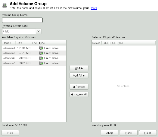
Figure 3.3 Creating a Volume Group
If you have multiple volume groups dened and want to add or remove PVs, select the
volume group in the Volume Management list and click Resize. In the following window,
you can add or remove PVs to the selected volume group.
3.2.2.2 Conguring Logical Volumes
After the volume group has been lled with PVs, dene the LVs which the operating
system should use in the next dialog. Choose the current volume group and change to
the Logical Volumes tab. Add,Edit,Resize, and Delete LVs as needed until all space
in the volume group has been occupied. Assign at least one LV to each volume group.
Advanced Disk Setup 85

Figure 3.4 Logical Volume Management
Click Add and go through the wizard-like pop-up that opens:
1. Enter the name of the LV. For a partition that should be mounted to /home, a self-
explanatory name like HOME could be used.
2. Select the size and the number of stripes of the LV. If you have only one PV, selecting
more than one stripe is not useful.
3. Choose the lesystem to use on the LV as well as the mount point.
By using stripes it is possible to distribute the data stream in the LV among several PVs
(striping). However, striping a volume can only be done over different PVs, each pro-
viding at least the amount of space of the volume. The maximum number of stripes
equals to the number of PVs, where Stripe "1" means "no striping". Striping only makes
sense with PVs on different hard disks, otherwise performance will decrease.
WARNING: Striping
YaST cannot, at this point, verify the correctness of your entries concerning
striping. Any mistake made here is apparent only later when the LVM is imple-
mented on disk.
86 Reference
If you have already congured LVM on your system, the existing logical volumes can
also be used. Before continuing, assign appropriate mount points to these LVs. With
Finish, return to the YaST Expert Partitioner and nish your work there.
3.3 Soft RAID Conguration
The purpose of RAID (redundant array of independent disks) is to combine several
hard disk partitions into one large virtual hard disk to optimize performance and/or
data security. Most RAID controllers use the SCSI protocol because it can address a
larger number of hard disks in a more effective way than the IDE protocol. It is also
more suitable for the parallel command processing. There are some RAID controllers
that support IDE or SATA hard disks. Soft RAID provides the advantages of RAID
systems without the additional cost of hardware RAID controllers. However, this requires
some CPU time and has memory requirements that make it unsuitable for high perfor-
mance computers.
With openSUSE® , you can combine several hard disks into one soft RAID system.
RAID implies several strategies for combining several hard disks in a RAID system,
each with different goals, advantages, and characteristics. These variations are commonly
known as RAID levels.
Common RAID levels are:
RAID 0
This level improves the performance of your data access by spreading out blocks
of each le across multiple disk drives. Actually, this is not really a RAID, because
it does not provide data backup, but the name RAID 0 for this type of system is
commonly used. With RAID 0, two or more hard disks are pooled together. Perfor-
mance is enhanced, but the RAID system is destroyed and your data lost if even
one hard disk fails.
RAID 1
This level provides adequate security for your data, because the data is copied to
another hard disk 1:1. This is known as hard disk mirroring. If one disk is destroyed,
a copy of its contents is available on the other one. All disks but one could be
damaged without endangering your data. However, if the damage is not detected,
the damaged data can be mirrored to the undamaged disk. This could result in the
same loss of data. The writing performance suffers in the copying process compared
to using single disk access (10 to 20 % slower), but read access is signicantly
Advanced Disk Setup 87
faster in comparison to any one of the normal physical hard disks. The reason is
that the duplicate data can be parallel-scanned. Generally it can be said that Level 1
provides nearly twice the read transfer rate of single disks and almost the same
write transfer rate as single disks.
RAID 5
RAID 5 is an optimized compromise between Level 0 and Level 1, in terms of
performance and redundancy. The hard disk space equals the number of disks used
minus one. The data is distributed over the hard disks as with RAID 0. Parity blocks,
created on one of the partitions, exist for security reasons. They are linked to each
other with XOR, enabling the contents to be reconstructed by the corresponding
parity block in case of system failure. With RAID 5, no more than one hard disk
can fail at the same time. If one hard disk fails, it must be replaced as soon as pos-
sible to avoid the risk of losing data.
RAID 6
To further increase the reliability of the RAID system, it is possible to use RAID 6.
In this level, even if two disks fail, the array still can be reconstructed. With RAID 6,
at least 4 hard disks are needed to run the array. Note that when running as software
raid, this conguration needs a considerable amount of CPU time and memory.
RAID 10 (RAID 1+0)
This RAID implementation combines features of RAID 0 and RAID 1: the data
are rst mirrored in separate disk arrays, which are inserted into a new RAID 0;
type array. In each RAID 1 sub-array, one disk can fail without any damage to the
data. RAID 10 is used for database application where a huge load is expected.
Other RAID Levels
Several other RAID levels have been developed (RAID 2, RAID 3, RAID 4, RAIDn,
RAID 10, RAID 0+1, RAID 30, RAID 50, etc.), some of them being proprietary
implementations created by hardware vendors. These levels are not very common
and therefore are not explained here.
3.3.1 Soft RAID Conguration with YaST
The YaST RAID conguration can be reached from the YaST Expert Partitioner, de-
scribed in Section 3.1, “Using the YaST Partitioner” (page 73). This partitioning tool
enables you to edit and delete existing partitions and create new ones to be used with
soft RAID:
88 Reference

1Select a hard disk from Hard Disks.
2Change to the Partitions tab.
3Click Add and enter the desired size of the raid partition on this disk.
4Use Do not Format the Partition and change the File System ID to 0xFD Linux
RAID. Do not mount this partition.
5Repeat this procedure until you have dened all the desired physical volumes on the
available disks.
For RAID 0 and RAID 1, at least two partitions are needed—for RAID 1, usually ex-
actly two and no more. If RAID 5 is used, at least three partitions are required. It is
recommended to utilize partitions of the same size only. The RAID partitions should
be located on different hard disks to decrease the risk of losing data if one is defective
(RAID 1 and 5) and to optimize the performance of RAID 0. After creating all the
partitions to use with RAID, click RAID >Add RAID to start the RAID conguration.
In the next dialog, choose between RAID levels 0, 1, 5, 6 and 10. Then, select all parti-
tions with either the “Linux RAID” or “Linux native” type that should be used by the
RAID system. No swap or DOS partitions are shown.
Figure 3.5 RAID Partitions
To add a previously unassigned partition to the selected RAID volume, rst click the
partition then Add. Assign all partitions reserved for RAID. Otherwise, the space on
Advanced Disk Setup 89
the partition remains unused. After assigning all partitions, click Next to select the
available RAID Options.
In this last step, set the le system to use as well as encryption and the mount point for
the RAID volume. After completing the conguration with Finish, see the /dev/md0
device and others indicated with RAID in the expert partitioner.
3.3.2 Troubleshooting
Check the le /proc/mdstat to nd out whether a RAID partition has been damaged.
In the event of a system failure, shut down your Linux system and replace the defective
hard disk with a new one partitioned the same way. Then restart your system and enter
the command mdadm /dev/mdX --add /dev/sdX. Replace 'X' with your partic-
ular device identiers. This integrates the hard disk automatically into the RAID system
and fully reconstructs it.
Note that although you can access all data during the rebuild, you may encounter some
performance issues until the RAID has been fully rebuilt.
3.3.3 For More Information
Conguration instructions and more details for soft RAID can be found in the HOWTOs
at:
•/usr/share/doc/packages/mdadm/Software-RAID.HOWTO.html
•http://raid.wiki.kernel.org
Linux RAID mailing lists are available, such as http://marc.info/?l=linux
-raid.
90 Reference
Part II. System

4
32-Bit and 64-Bit Applications
in a 64-Bit System
Environment
openSUSE® is available for 64-bit platforms. This does not necessarily mean that all
the applications included have already been ported to 64-bit platforms. openSUSE
supports the use of 32-bit applications in a 64-bit system environment. This chapter
offers a brief overview of how this support is implemented on 64-bit openSUSE plat-
forms. It explains how 32-bit applications are executed (runtime support) and how 32-
bit applications should be compiled to enable them to run both in 32-bit and 64-bit
system environments. Additionally, nd information about the kernel API and an ex-
planation of how 32-bit applications can run under a 64-bit kernel.
openSUSE for the 64-bit platforms amd64 and Intel 64 is designed so that existing 32-
bit applications run in the 64-bit environment “out-of-the-box.” This support means
that you can continue to use your preferred 32-bit applications without waiting for a
corresponding 64-bit port to become available.
4.1 Runtime Support
IMPORTANT: Conicts between Application Versions
If an application is available both for 32-bit and 64-bit environments, parallel
installation of both versions is bound to lead to problems. In such cases, decide
on one of the two versions and install and use this.
32-Bit and 64-Bit Applications in a 64-Bit System Environment 93

An exception to this rule is PAM (pluggable authentication modules). openSUSE
uses PAM in the authentication process as a layer that mediates between user
and application. On a 64-bit operating system that also runs 32-bit applications
it is necessary to always install both versions of a PAM module.
To be executed correctly, every application requires a range of libraries. Unfortunately,
the names for the 32-bit and 64-bit versions of these libraries are identical. They must
be differentiated from each other in another way.
To retain compatibility with the 32-bit version, the libraries are stored at the same place
in the system as in the 32-bit environment. The 32-bit version of libc.so.6 is located
under /lib/libc.so.6 in both the 32-bit and 64-bit environments.
All 64-bit libraries and object les are located in directories called lib64. The 64-bit
object les that you would normally expect to nd under /lib and /usr/lib are
now found under /lib64 and /usr/lib64. This means that there is space for the
32-bit libraries under /lib and /usr/lib, so the lename for both versions can re-
main unchanged.
Subdirectories of 32-bit /lib directories which contain data content that does not de-
pend on the word size are not moved. This scheme conforms to LSB (Linux Standards
Base) and FHS (File System Hierarchy Standard).
4.2 Software Development
A biarch development tool chain allows generation of 32-bit and 64-bit objects. The
default is to compile 64-bit objects. It is possible to generate 32-bit objects by using
special ags. For GCC, this special ag is -m32.
All header les must be written in an architecture-independent form. The installed 32-
bit and 64-bit libraries must have an API (application programming interface) that
matches the installed header les. The normal openSUSE environment is designed ac-
cording to this principle. In the case of manually updated libraries, resolve these issues
yourself.
94 Reference
4.3 Software Compilation on Biarch
Platforms
To develop binaries for the other architecture on a biarch architecture, the respective
libraries for the second architecture must additionally be installed. These packages are
called rpmname-32bit. You also need the respective headers and libraries from the
rpmname-devel packages and the development libraries for the second architecture
from rpmname-devel-32bit.
Most open source programs use an autoconf-based program conguration. To use
autoconf for conguring a program for the second architecture, overwrite the normal
compiler and linker settings of autoconf by running the configure script with
additional environment variables.
The following example refers to an x86_64 system with x86 as the second architecture.
1Use the 32-bit compiler:
CC="gcc -m32"
2Instruct the linker to process 32-bit objects (always use gcc as the linker front-end):
LD="gcc -m32"
3Set the assembler to generate 32-bit objects:
AS="gcc -c -m32"
4Specify linker ags, such as the location of 32-bit libraries, for example:
LDFLAGS="-L/usr/lib"
5Specify the location for the 32-bit object code libraries:
--libdir=/usr/lib
6Specify the location for the 32-bit X libraries:
--x-libraries=/usr/lib
32-Bit and 64-Bit Applications in a 64-Bit System Environment 95

Not all of these variables are needed for every program. Adapt them to the respective
program.
CC="gcc -m32"
LDFLAGS="-L/usr/lib;"
./configure --prefix=/usr --libdir=/usr/lib --x-libraries=/usr/lib
make
make install
4.4 Kernel Specications
The 64-bit kernels for x86_64 offer both a 64-bit and a 32-bit kernel ABI (application
binary interface). The latter is identical with the ABI for the corresponding 32-bit kernel.
This means that the 32-bit application can communicate with the 64-bit kernel in the
same way as with the 32-bit kernel.
The 32-bit emulation of system calls for a 64-bit kernel does not support all the APIs
used by system programs. This depends on the platform. For this reason, a small number
of applications, like lspci, must be compiled.
A 64-bit kernel can only load 64-bit kernel modules that have been specially compiled
for this kernel. It is not possible to use 32-bit kernel modules.
TIP: Kernel-loadable Modules
Some applications require separate kernel-loadable modules. If you intend to
use such a 32-bit application in a 64-bit system environment, contact the
provider of this application and SUSE to make sure that the 64-bit version of
the kernel-loadable module and the 32-bit compiled version of the kernel API
are available for this module.
96 Reference
5
Booting and Conguring a
Linux System
With the release of openSUSE 12.1 switched from System-V init to systemd. When
booting openSUSE, systemd is started as the very rts process and is responsible for
starting, stopping and controlling all other processes on the system. See http://en
.opensuse.org/SDB:Systemd for more information.
Booting and Conguring a Linux System 97
6
The Boot Loader GRUB
This chapter describes how to congure GRUB (Grand Unied Bootloader), the boot
loader used in openSUSE®. A special YaST module is available for conguring all
settings. If you are not familiar with the subject of booting in Linux, read the following
sections to acquire some background information. This chapter also describes some of
the problems frequently encountered when booting with GRUB and their solutions.
This chapter focuses on boot management and the conguration of the boot loader
GRUB. The boot procedure as a whole is outlined in Chapter 5, Booting and Conguring
a Linux System (page 97). A boot loader represents the interface between the machine
(BIOS) and the operating system (openSUSE). The conguration of the boot loader
directly impacts the start of the operating system.
The following terms appear frequently in this chapter and might need some explanation:
MBR (Master Boot Record)
The structure of the MBR is dened by an operating system–independent conven-
tion. The rst 446 bytes are reserved for the program code. They typically hold
part of a boot loader program or an operating system selector. The next 64 bytes
provide space for a partition table of up to four entries. The partition table contains
information about the partitioning of the hard disk and the le system types. The
operating system needs this table for handling the hard disk. With conventional
generic code in the MBR, exactly one partition must be marked active. The last
two bytes of the MBR must contain a static “magic number” (AA55). An MBR
containing a different value is regarded as invalid by some BIOSes, so is not con-
sidered for booting.
The Boot Loader GRUB 99
Boot Sectors
Boot sectors are the rst sectors of hard disk partitions with the exception of the
extended partition, which merely serves as a “container” for other partitions. These
boot sectors have 512 bytes of space for code used to boot an operating system in-
stalled in the respective partition. This applies to boot sectors of formatted DOS,
Windows, and OS/2 partitions, which also contain some basic important data of
the le system. In contrast, the boot sectors of Linux partitions are initially empty
after setting up a le system other than XFS. Therefore, a Linux partition is not
bootable by itself, even if it contains a kernel and a valid root le system. A boot
sector with valid code for booting the system has the same magic number as the
MBR in its last two bytes (AA55).
6.1 Booting with GRUB
GRUB comprises two stages. Stage 1 consists of 512 bytes and its only task is to load
the second stage of the boot loader. Subsequently, stage 2 is loaded. This stage contains
the main part of the boot loader.
In some congurations, an intermediate stage 1.5 can be used, which locates and loads
stage 2 from an appropriate le system. If possible, this method is chosen by default
on installation or when initially setting up GRUB with YaST.
Stage 2 is able to access many le systems. Currently, ext2, ext3, ReiserFS, Minix, and
the DOS FAT le system used by Windows are supported. To a certain extent, XFS,
and UFS and FFS used by BSD systems are also supported. Since version 0.95 GRUB
is also able to boot from a CD or DVD containing an ISO 9660 standard le system
pursuant to the “El Torito” specication. Even before the system is booted, GRUB can
access le systems of supported BIOS disk devices (oppy disks or hard disks, CD
drives and DVD drives detected by the BIOS). Therefore, changes to the GRUB con-
guration le (menu.lst) do not require a new installation of the boot manager. When
the system is booted, GRUB reloads the menu le with the valid paths and partition
data of the kernel or the initial RAM disk (initrd) and locates these les.
The actual conguration of GRUB is based on four les that are described below:
/boot/grub/menu.lst
This le contains all information about partitions or operating systems that can be
booted with GRUB. Without this information, the GRUB command line prompts
100 Reference
the user for how to proceed. For details, see Section 6.1.1.3, “Editing Menu Entries
during the Boot Procedure” (page 106).
/boot/grub/device.map
This le translates device names from the GRUB and BIOS notation to Linux device
names.
/etc/grub.conf
This le contains the commands, parameters and options the GRUB shell needs
for installing the boot loader correctly.
/etc/sysconfig/bootloader
This le is read by the perl-bootloader library which is used when conguring the
bootloader with YaST and every time a new kernel is installed. It contains congu-
ration options (such as kernel parameters) that will be added by default to the
bootloader conguration le.
GRUB can be controlled in various ways. Boot entries from an existing conguration
can be selected from the graphical menu (splash screen). The conguration is loaded
from the le menu.lst.
In GRUB, all boot parameters can be changed prior to booting. For example, errors
made when editing the menu le can be corrected in this way. Boot commands can also
be entered interactively at a kind of input prompt. For details, see Section 6.1.1.3,
“Editing Menu Entries during the Boot Procedure” (page 106). GRUB offers the possi-
bility of determining the location of the kernel and the initrd prior to booting. In
this way, you can even boot an installed operating system for which no entry exists in
the boot loader conguration.
GRUB actually exists in two versions: as a boot loader and as a normal Linux program
in /usr/sbin/grub. The latter is referred to as the GRUB shell. It provides an em-
ulation of GRUB in the installed system and can be used to install GRUB or test new
settings before applying them. The functionality to install GRUB as the boot loader on
a hard disk or oppy disk is integrated in GRUB in the form of the command setup.
This is available in the GRUB shell when Linux is loaded.
The Boot Loader GRUB 101
6.1.1 The File /boot/grub/menu.lst
The graphical splash screen with the boot menu is based on the GRUB conguration
le /boot/grub/menu.lst, which contains all information about all partitions or
operating systems that can be booted by the menu.
Every time the system is booted, GRUB loads the menu le from the le system. For
this reason, GRUB does not need to be reinstalled after every change to the le. Use
the YaST boot loader to modify the GRUB conguration as described in Section 6.2,
“Conguring the Boot Loader with YaST” (page 110).
The menu le contains commands. The syntax is very simple. Every line contains a
command followed by optional parameters separated by spaces like in the shell. For
historical reasons, some commands permit an =in front of the rst parameter. Comments
are introduced by a hash (#).
To identify the menu items in the menu overview, set a title for every entry. The
text (including any spaces) following the keyword title is displayed as a selectable
option in the menu. All commands up to the next title are executed when this menu
item is selected.
The simplest case is the redirection to boot loaders of other operating systems. The
command is chainloader and the argument is usually the boot block of another
partition, in GRUB block notation. For example:
chainloader (hd0,3)+1
The device names in GRUB are explained in Section 6.1.1.1, “Naming Conventions
for Hard Disks and Partitions” (page 103). This example species the rst block of the
fourth partition of the rst hard disk.
Use the command kernel to specify a kernel image. The rst argument is the path to
the kernel image in a partition. The other arguments are passed to the kernel on its
command line.
If the kernel does not have built-in drivers for access to the root partition or a recent
Linux system with advanced hotplug features is used, initrd must be specied with
a separate GRUB command whose only argument is the path to the initrd le. Be-
cause the loading address of the initrd is written into the loaded kernel image, the
command initrd must follow after the kernel command.
102 Reference
The command root simplies the specication of kernel and initrd les. The only
argument of root is a device or a partition. This device is used for all kernel, initrd,
or other le paths for which no device is explicitly specied until the next root com-
mand.
The boot command is implied at the end of every menu entry, so it does not need to
be written into the menu le. However, if you use GRUB interactively for booting, you
must enter the boot command at the end. The command itself has no arguments. It
merely boots the loaded kernel image or the specied chain loader.
After writing all menu entries, dene one of them as the default entry. Otherwise,
the rst one (entry 0) is used. You can also specify a time-out in seconds after which
the default entry should boot. timeout and default usually precede the menu entries.
An example le is described in Section 6.1.1.2, “An Example Menu File” (page 104).
6.1.1.1 Naming Conventions for Hard Disks and
Partitions
The naming convention GRUB uses for hard disks and partitions differ from that used
for normal Linux devices. It more closely resembles the simple disk enumeration the
BIOS does and the syntax is similar to that used in some BSD derivatives. In GRUB,
the numbering of the partitions start with zero. This means that (hd0,0) is the rst
partition of the rst hard disk. On a common desktop machine with a hard disk connected
as primary master, the corresponding Linux device name is /dev/sda1.
The four possible primary partitions are assigned the partition numbers 0to 3. The
logical partitions are numbered from 4:
(hd0,0) first primary partition of the first hard disk
(hd0,1) second primary partition
(hd0,2) third primary partition
(hd0,3) fourth primary partition (usually an extended partition)
(hd0,4) first logical partition
(hd0,5) second logical partition
Being dependent on BIOS devices, GRUB does not distinguish between PATA (IDE),
SATA, SCSI, and hardware RAID devices. All hard disks recognized by the BIOS or
other controllers are numbered according to the boot sequence preset in the BIOS.
The Boot Loader GRUB 103
Unfortunately, it is often not possible to map the Linux device names to BIOS device
names exactly. It generates this mapping with the help of an algorithm and saves it to
the le device.map, which can be edited if necessary. Information about the le
device.map is available in Section 6.1.2, “The File device.map” (page 107).
A complete GRUB path consists of a device name written in parentheses and the path
to the le in the le system in the specied partition. The path begins with a slash. For
example, the bootable kernel could be specied as follows on a system with a single
PATA (IDE) hard disk containing Linux in its rst partition:
(hd0,0)/boot/vmlinuz
6.1.1.2 An Example Menu File
The following example shows the structure of a GRUB menu le. The example instal-
lation has a Linux boot partition under /dev/sda5, a root partition under /dev/
sda7 and a Windows installation under /dev/sda1.
gfxmenu (hd0,4)/boot/message❶
color white/blue black/light-gray❷
default 0❸
timeout 8❹
title linux❺
root (hd0,4)
kernel /boot/vmlinuz root=/dev/sda7 vga=791 resume=/dev/sda9
initrd /boot/initrd
title windows❻
rootnoverify (hd0,0)
chainloader +1
title floppy❼
rootnoverify (hd0,0)
chainloader (fd0)+1
title failsafe❽
root (hd0,4)
kernel /boot/vmlinuz.shipped root=/dev/sda7 ide=nodma \
apm=off acpi=off vga=normal nosmp maxcpus=0 3 noresume
initrd /boot/initrd.shipped
The rst block denes the conguration of the splash screen:
❶The background image message is located in the /boot directory of the /dev/
sda5 partition.
104 Reference
❷Color scheme: white (foreground), blue (background), black (selection) and light
gray (background of the selection). The color scheme has no effect on the splash
screen, only on the customizable GRUB menu that you can access by exiting the
splash screen with Esc.
❸The rst (0) menu entry title linux is booted by default.
❹After eight seconds without any user input, GRUB automatically boots the default
entry. To deactivate automatic boot, delete the timeout line. If you set timeout
0, GRUB boots the default entry immediately.
The second and largest block lists the various bootable operating systems. The sections
for the individual operating systems are introduced by title.
❺The rst entry (title linux) is responsible for booting openSUSE. The kernel
(vmlinuz) is located in the rst logical partition (the boot partition) of the rst
hard disk. Kernel parameters, such as the root partition and VGA mode, are ap-
pended here. The root partition is specied according to the Linux naming con-
vention (/dev/sda7/) because this information is read by the kernel and has
nothing to do with GRUB. The initrd is also located in the rst logical partition
of the rst hard disk.
❻The second entry is responsible for loading Windows. Windows is booted from
the rst partition of the rst hard disk (hd0,0). The command chainloader
+1 causes GRUB to read and execute the rst sector of the specied partition.
❼The next entry enables booting from oppy disk without modifying the BIOS
settings.
❽The boot option failsafe starts Linux with a selection of kernel parameters
that enables Linux to boot even on problematic systems.
The menu le can be changed whenever necessary. GRUB then uses the modied set-
tings during the next boot. Edit the le permanently using YaST or an editor of your
choice. Alternatively, make temporary changes interactively using the edit function of
GRUB. See Section 6.1.1.3, “Editing Menu Entries during the Boot Procedure”
(page 106).
The Boot Loader GRUB 105

6.1.1.3 Editing Menu Entries during the Boot
Procedure
In the graphical boot menu, select the operating system to boot with the arrow keys. If
you select a Linux system, you can enter additional boot parameters at the boot prompt.
To edit individual menu entries directly, press Esc to exit the splash screen and get to
the GRUB text-based menu then press E. Changes made in this way only apply to the
current boot and are not adopted permanently.
IMPORTANT: Keyboard Layout during the Boot Procedure
The US keyboard layout is the only one available when booting. See Figure “US
Keyboard Layout” (↑Start-Up).
Editing menu entries facilitates the repair of a defective system that can no longer be
booted, because the faulty conguration le of the boot loader can be circumvented by
manually entering parameters. Manually entering parameters during the boot procedure
is also useful for testing new settings without impairing the native system.
After activating the editing mode, use the arrow keys to select the menu entry of the
conguration to edit. To make the conguration editable, press Eagain. In this way,
edit incorrect partitions or path specications before they have a negative effect on the
boot process. Press Enter to exit the editing mode and return to the menu. Then press
Bto boot this entry. Further possible actions are displayed in the help text at the bottom.
To enter changed boot options permanently and pass them to the kernel, open the le
menu.lst as the user root and append the respective kernel parameters to the existing
line, separated by spaces:
title linux
root(hd0,0)
kernel /vmlinuz root=/dev/sda3 additional parameter
initrd /initrd
GRUB automatically adopts the new parameters the next time the system is booted.
Alternatively, this change can also be made with the YaST boot loader module. Append
the new parameters to the existing line, separated by spaces.
106 Reference
6.1.2 The File device.map
The le device.map maps GRUB and BIOS device names to Linux device names.
In a mixed system containing PATA (IDE) and SCSI hard disks, GRUB must try to
determine the boot sequence by a special procedure, because GRUB may not have access
to the BIOS information on the boot sequence. GRUB saves the result of this analysis
in the le /boot/grub/device.map. Example device.map les for a system
on which the boot sequence in the BIOS is set to PATA before SCSI could look as
follows:
(fd0) /dev/fd0
(hd0) /dev/sda
(hd1) /dev/sdb
or
(fd0) /dev/fd0
(hd0) /dev/disk-by-id/DISK1 ID
(hd1) /dev/disk-by-id/DISK2 ID
Because the order of PATA (IDE), SCSI and other hard disks depends on various factors
and Linux is not able to identify the mapping, the sequence in the le device.map
can be set manually. If you encounter problems when booting, check if the sequence
in this le corresponds to the sequence in the BIOS and use the GRUB prompt to
modify it temporarily, if necessary. After the Linux system has booted, the le device
.map can be edited permanently with the YaST boot loader module or an editor of
your choice.
After manually changing device.map, execute the following command to reinstall
GRUB. This command causes the le device.map to be reloaded and the commands
listed in grub.conf to be executed:
grub --batch < /etc/grub.conf
6.1.3 The File /etc/grub.conf
The third important GRUB conguration le after menu.lst and device.map is
/etc/grub.conf. This le contains the commands, parameters and options the
GRUB shell needs for installing the boot loader correctly:
setup --stage2=/boot/grub/stage2 --force-lba (hd0,1) (hd0,1)
quit
The Boot Loader GRUB 107

This command tells GRUB to automatically install the boot loader to the second partition
on the rst hard disk (hd0,1) using the boot images located on the same partition. The
--stage2=/boot/grub/stage2 parameter is needed to install the stage2 image
from a mounted le system. Some BIOSes have a faulty LBA support implementation,
--force-lba provides a solution to ignore them.
6.1.4 The File /etc/syscong/bootloader
This conguration le is only used when conguring the bootloader with YaST and
every time a new kernel is installed. It is evaluated by the perl-bootloader library which
modies the bootloader conguration le (for example /boot/grub/menu.lst
for GRUB) accordingly. /etc/sysconfig/bootloader is not a GRUB specic
conguration le - the values are applied to any bootloader installed on openSUSE.
NOTE: Bootloader Conguration after a Kernel Update
Every time a new kernel is installed, the perl bootloader writes a new bootloader
conguration le (for example /boot/grub/menu.lst for GRUB) using the
defaults specied in /etc/sysconfig/bootloader. If you are using a
customized set of kernel parameters, make sure to adjust the relevant defaults
in /etc/sysconfig/bootloader according to your needs.
LOADER_TYPE
Species the bootloader installed on the system (e.g. GRUB or LILO). Do not
modify—use YaST to change the bootloader as described in Procedure 6.6,
“Changing the Boot Loader Type” (page 115).
DEFAULT_VGA / FAILSAFE_VGA / XEN_VGA
Screen resolution and color depth of the framebuffer used during booting are con-
gured with the kernel parameter vga. These values dene which resolution and
color depth to use for the default boot entry, the failsafe and the XEN entry. The
following values are valid:
Table 6.1 Screen Resolution and Color Depth Reference
1600x12001280x10241024x768800x600640x480
0x31C0x3070x3050x3030x3018bit
108 Reference

1600x12001280x10241024x768800x600640x480
0x31D0x3190x3160x3130x31015bit
0x31E0x31A0x3170x3140x31116bit
0x31F0x31B0x3180x3150x31224bit
DEFAULT_APPEND / FAILSAFE_APPEND / XEN_KERNEL_APPEND
Kernel parameters (other than vga) that are automatically appended to the default,
failsafe and XEN boot entries in the bootloader conguration le.
CYCLE_DETECTION / CYCLE_NEXT_ENTRY
Congure whether to use boot cycle detection and if so, which alternative entry
from /boot/grub/menu.lst to boot in case of a reboot cycle (e.g.
Failsafe). See /usr/share/doc/packages/bootcycle/README for
detailed information.
6.1.5 Setting a Boot Password
Even before the operating system is booted, GRUB enables access to le systems. Users
without root permissions can access les in your Linux system to which they have no
access once the system is booted. To block this kind of access or to prevent users from
booting certain operating systems, set a boot password.
IMPORTANT: Boot Password and Splash Screen
If you use a boot password for GRUB, the usual splash screen is not displayed.
As the user root, proceed as follows to set a boot password:
1At the root prompt, encrypt the password using grub-md5-crypt:
# grub-md5-crypt
Password: ****
Retype password: ****
Encrypted: $1$lS2dv/$JOYcdxIn7CJk9xShzzJVw/
2Paste the encrypted string into the global section of the le menu.lst:
The Boot Loader GRUB 109
gfxmenu (hd0,4)/message
color white/blue black/light-gray
default 0
timeout 8
password --md5 $1$lS2dv/$JOYcdxIn7CJk9xShzzJVw/
Now GRUB commands can only be executed at the boot prompt after pressing P
and entering the password. However, users can still boot all operating systems from
the boot menu.
3To prevent one or several operating systems from being booted from the boot menu,
add the entry lock to every section in menu.lst that should not be bootable
without entering a password. For example:
title linux
kernel (hd0,4)/vmlinuz root=/dev/sda7 vga=791
initrd (hd0,4)/initrd
lock
After rebooting the system and selecting the Linux entry from the boot menu, the
following error message is displayed:
Error 32: Must be authenticated
Press Enter to enter the menu. Then press Pto get a password prompt. After entering
the password and pressing Enter, the selected operating system (Linux in this case)
should boot.
6.2 Conguring the Boot Loader with
YaST
The easiest way to congure the boot loader in your openSUSE system is to use the
YaST module. In the YaST Control Center, select System >Boot Loader. As in Fig-
ure 6.1, “Boot Loader Settings” (page 111), this shows the current boot loader congu-
ration of your system and allows you to make changes.
110 Reference
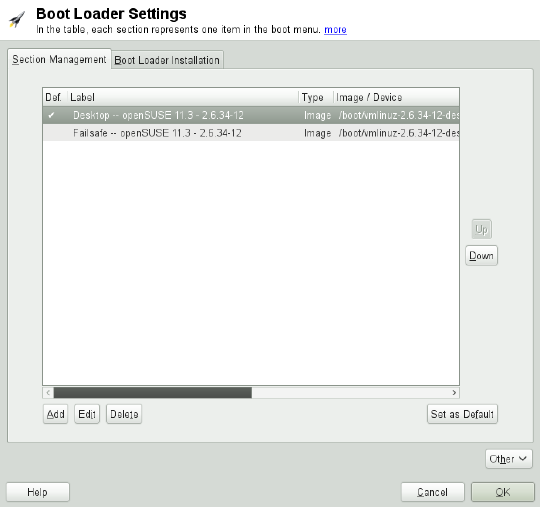
Figure 6.1 Boot Loader Settings
Use the Section Management tab to edit, change and delete boot loader sections for the
individual operating systems. To add an option, click Add. To change the value of an
existing option, select it with the mouse and click Edit. To remove an existing entry,
select it and click Delete. If you are not familiar with boot loader options, read Sec-
tion 6.1, “Booting with GRUB” (page 100) rst.
Use the Boot Loader Installation tab to view and change settings related to type, location
and advanced loader settings.
Click Other to access advanced conguration options. The build-in editor lets you
change the GRUB conguration les. For details, see Section 6.1, “Booting with GRUB”
(page 100). You can also delete the existing conguration and Start from Scratch or let
YaST Propose a New Conguration. It is also possible to write the conguration to
disk or reread the conguration from the disk. To restore the original Master Boot
Record (MBR) that was saved during the installation, choose Restore MBR of Hard
Disk.
The Boot Loader GRUB 111
6.2.1 Adjusting the Default Boot Entry
To change the system that is booted by default, proceed as follows:
Procedure 6.1 Setting the Default System
1Open the Section Management tab.
2Select the desired entry from the list.
3Click Set as Default.
4Click OK to activate these changes.
6.2.2 Modifying the Boot Loader Location
To modify the location of the boot loader, follow these steps:
Procedure 6.2 Changing the Boot Loader Location
1Select the Boot Loader Installation tab and then choose one of the following options
for Boot Loader Location:
Boot from Master Boot Record
This installs the boot loader in the MBR of the rst disk (according to the boot
sequence preset in the BIOS).
Boot from Root Partition
This installs the boot loader in the boot sector of the /partition (this is the de-
fault).
Boot from Boot Partition
This installs the boot loader in the boot sector of the /boot partition.
Boot from Extended Partition
This installs the boot loader in the extended partition container.
Custom Boot Partition
Use this option to specify the location of the boot loader manually.
112 Reference

2Click OK to apply your changes.
6.2.3 Changing the Boot Loader Time-Out
The boot loader does not boot the default system immediately. During the time-out,
you can select the system to boot or write some kernel parameters. To set the boot
loader time-out, proceed as follows:
Procedure 6.3 Changing the Boot Loader Time-Out
1Open the Boot Loader Installation tab.
2Click Boot Loader Options.
3Change the value of Time-Out in Seconds by typing in a new value and clicking the
appropriate arrow key with your mouse, or by using the arrow keys on the keyboard.
4Click OK twice to save the changes.
WARNING: Timeout of 0 Seconds
When setting the timeout to 0 seconds, you will not be able to access GRUB
during boot time. When having set the default boot option to a non-Linux
operation system at the same time, this effectively disables access to the Linux
system.
6.2.4 Setting a Boot Password
Using this YaST module, you can also set a password to protect booting. This gives
you an additional level of security.
Procedure 6.4 Setting a Boot Loader Password
1Open the Boot Loader Installation tab.
2Click Boot Loader Options.
The Boot Loader GRUB 113
3Activate the Protect Boot Loader with Password option with a click and type in your
Password twice.
4Click OK twice to save the changes.
6.2.5 Adjusting the Disk Order
If your computer has more than one hard disk, you can specify the boot sequence of
the disks to match the BIOS setup of the machine (see Section 6.1.2, “The File de-
vice.map” (page 107)). To do so, proceed as follows:
Procedure 6.5 Setting the Disk Order
1Open the Boot Loader Installation tab.
2Click Boot Loader Installation Details.
3If more than one disk is listed, select a disk and click Up or Down to reorder the
displayed disks.
4Click OK two times to save the changes.
6.2.6 Conguring Advanced Options
Advanced boot options can be congured via Boot Loader Installation >Boot Loader
Options. Normally, it should not be necessary to change the default settings.
Set Active Flag in Partition Table for Boot Partition
Activates the partition that contains the boot loader. Some legacy operating systems
(such as Windows 98) can only boot from an active partition.
Write Generic Boot Code to MBR
Replaces the current MBR with generic, operating system independent code.
Debugging Flag
Sets GRUB in debug mode where it displays messages to show disk activity.
Hide Boot Menu
Hides the boot menu and boots the default entry.
114 Reference

WARNING
When hiding the boot menu, you will not be able to access GRUB during
boot time. When having set the default boot option to a non-Linux opera-
tion system at the same time, this effectively disables access to the Linux
system.
Use Trusted GRUB
Starts the Trusted GRUB which supports trusted computing functionality.
Enable Acoustic Signals
Enables or disables acoustic signals in GRUB.
Graphical Menu File
Path to the graphics le used when displaying the boot screen.
Use Serial Console
If your machine is controlled via a serial console, activate this option and specify
which COM port to use at which speed. See info grub or http://www.gnu
.org/software/grub/manual/grub.html#Serial-terminal
6.2.7 Changing Boot Loader Type
Set the boot loader type in Boot Loader Installation. The default boot loader in open-
SUSE is GRUB. To use LILO or ELILO, proceed as follows:
WARNING: LILO is unsupported
Using LILO is not recommended—it is unsupported on openSUSE. Only use it
in special cases.
Procedure 6.6 Changing the Boot Loader Type
1Select the Boot Loader Installation tab.
2For Boot Loader, select LILO.
3In the dialog box that opens, select one of the following actions:
The Boot Loader GRUB 115

Propose New Conguration
Have YaST propose a new conguration.
Convert Current Conguration
Have YaST convert the current conguration. When converting the conguration,
some settings may be lost.
Start New Conguration from Scratch
Write a custom conguration. This action is not available during the installation
of openSUSE.
Read Conguration Saved on Disk
Load your own /etc/lilo.conf. This action is not available during the in-
stallation of openSUSE.
4Click OK two times to save the changes.
During the conversion, the old GRUB conguration is saved to the disk. To use it,
simply change the boot loader type back to GRUB and choose Restore Conguration
Saved before Conversion. This action is available only on an installed system.
NOTE: Custom Boot Loader
To use a boot loader other than GRUB or LILO, select Do Not Install Any Boot
Loader. Read the documentation of your boot loader carefully before choosing
this option.
6.3 Uninstalling the Linux Boot
Loader
YaST can be used to uninstall the Linux boot loader and restore the MBR to the state
it had prior to the installation of Linux. During the installation, YaST automatically
creates a backup copy of the original MBR and restores it upon request.
To uninstall GRUB, start YaST and click System >Boot Loader to start the boot loader
module. Select Other >Restore MBR of Hard Disk and conrm with Yes, Rewrite.
116 Reference
6.4 Creating Boot CDs
If problems occur while booting your system using a boot manager or if the boot man-
ager cannot be installed on your hard disk disk, it is also possible to create a bootable
CD with all the necessary start-up les for Linux. This requires a CD writer be installed
in your system.
Creating a bootable CD-ROM with GRUB merely requires a special form of stage2
called stage2_eltorito and, optionally, a customized menu.lst. The classic
les stage1 and stage2 are not required.
Procedure 6.7 Creating Boot CDs
1Change into a directory in which to create the ISO image, for example: cd /tmp
2Create a subdirectory for GRUB and change into the newly created iso directory:
mkdir -p iso/boot/grub && cd iso
3Copy the kernel, the les stage2_eltorito,initrd,menu.lst and
message to iso/boot/:
cp /boot/vmlinuz boot/
cp /boot/initrd boot/
cp /boot/message boot/
cp /usr/lib/grub/stage2_eltorito boot/grub
cp /boot/grub/menu.lst boot/grub
4Replace the root (hdx,y)entries with root (cd) to point to the CD_ROM
device. You may also need to adjust the paths to the message le, the kernel and the
initrd—they need to point to /boot/message,/boot/vmlinuz and /boot/
initrd, respectively. After having made the adjustments, menu.lst should look
similar to the following example:
timeout 8
default 0
gfxmenu (cd)/boot/message
title Linux
root (cd)
kernel /boot/vmlinuz root=/dev/sda5 vga=794 resume=/dev/sda1 \
splash=verbose showopts
initrd /boot/initrd
The Boot Loader GRUB 117

Use splash=silent instead of splash=verbose to prevent the boot messages
from appearing during the boot procedure.
5Create the ISO image with the following command:
genisoimage -R -b boot/grub/stage2_eltorito -no-emul-boot \
-boot-load-size 4 -boot-info-table -iso-level 2 -input-charset utf-8 \
-o grub.iso /tmp/iso
6Write the resulting le grub.iso to a CD using your preferred utility. Do not burn
the ISO image as a data le, but use the option for burning a CD image in your
burning utility.
6.5 The Graphical SUSE Screen
The graphical SUSE screen is displayed on the rst console if the option vga=value
is used as a kernel parameter. If you install using YaST, this option is automatically
activated in accordance with the selected resolution and the graphics card. There are
three ways to disable the SUSE screen, if desired:
Disabling the SUSE Screen When Necessary
Enter the command echo 0 >/proc/splash on the command line to disable
the graphical screen. To activate it again, enter echo 1 >/proc/splash.
Disabling the SUSE screen by default
Add the kernel parameter splash=0 to your boot loader conguration. Chapter 6,
The Boot Loader GRUB (page 99) provides more information about this. However,
if you prefer the text mode (the default in earlier versions) set vga=normal.
Completely Disabling the SUSE Screen
Compile a new kernel and disable the option Use splash screen instead of boot logo
in framebuffer support. Disabling framebuffer support in the kernel automatically
disables the splash screen, as well.
WARNING: No Support
SUSE cannot provide any support for your system if you run it with a custom
kernel.
118 Reference
6.6 Troubleshooting
This section lists some of the problems frequently encountered when booting with
GRUB and a short description of possible solutions. Some of the problems are covered
in articles in the Support Database at http://en.opensuse.org/Portal:
Support_database. Use the search dialog to search for keywords like GRUB,boot
and boot loader.
GRUB and XFS
XFS leaves no room for stage1 in the partition boot block. Therefore, do not
specify an XFS partition as the location of the boot loader. This problem can be
solved by creating a separate boot partition that is not formatted with XFS.
GRUB Reports GRUB Geom Error
GRUB checks the geometry of connected hard disks when the system is booted.
Sometimes, the BIOS returns inconsistent information and GRUB reports a GRUB
Geom Error. In this case, update the BIOS.
GRUB also returns this error message if Linux was installed on an additional hard
disk that is not registered in the BIOS. stage1 of the boot loader is found and
loaded correctly, but stage2 is not found. This problem can be remedied by regis-
tering the new hard disk in the BIOS.
System Containing Several Hard Disks Does Not Boot
During the installation, YaST may have incorrectly determined the boot sequence
of the hard disks. For example, GRUB may regard the PATA (IDE) disk as hd0
and the SCSI disk as hd1, although the boot sequence in the BIOS is reversed
(SCSI before PATA).
In this case, correct the hard disks during the boot process with the help of the
GRUB command line. After the system has booted, edit device.map to apply
the new mapping permanently. Then check the GRUB device names in the les
/boot/grub/menu.lst and /boot/grub/device.map and reinstall the
boot loader with the following command:
grub --batch < /etc/grub.conf
The Boot Loader GRUB 119
Booting Windows from the Second Hard Disk
Some operating systems, such as Windows, can only boot from the rst hard disk.
If such an operating system is installed on a hard disk other than the rst hard disk,
you can effect a logical change for the respective menu entry.
...
title windows
map (hd0) (hd1)
map (hd1) (hd0)
chainloader(hd1,0)+1
...
In this example, Windows is started from the second hard disk. For this purpose,
the logical order of the hard disks is changed with map. This change does not affect
the logic within the GRUB menu le. Therefore, the second hard disk must be
specied for chainloader.
6.7 For More Information
Extensive information about GRUB is available at http://www.gnu.org/
software/grub/. Also refer to the grub info page. You can also search for the
keyword “GRUB” in the Support Database at http://en.opensuse.org/
Portal:Support_database to get information about special issues.
120 Reference
7
Special System Features
This chapter starts with information about various software packages, the virtual consoles
and the keyboard layout. We talk about software components like bash,cron and
logrotate, because they were changed or enhanced during the last release cycles.
Even if they are small or considered of minor importance, users may want to change
their default behavior, because these components are often closely coupled with the
system. The chapter concludes with a section about language and country-specic set-
tings (I18N and L10N).
7.1 Information about Special
Software Packages
The programs bash,cron,logrotate,locate,ulimit and free are very
important for system administrators and many users. Man pages and info pages are two
useful sources of information about commands, but both are not always available. GNU
Emacs is a popular and very congurable text editor.
7.1.1 The bash Package and /etc/prole
Bash is the default system shell. When used as a login shell, it reads several initialization
les. Bash processes them in the order they appear in this list:
Special System Features 121
1. /etc/profile
2. ~/.profile
3. /etc/bash.bashrc
4. ~/.bashrc
Make custom settings in ~/.profile or ~/.bashrc. To ensure the correct process-
ing of these les, it is necessary to copy the basic settings from /etc/skel/
.profile or /etc/skel/.bashrc into the home directory of the user. It is rec-
ommended to copy the settings from /etc/skel after an update. Execute the following
shell commands to prevent the loss of personal adjustments:
mv ~/.bashrc ~/.bashrc.old
cp /etc/skel/.bashrc ~/.bashrc
mv ~/.profile ~/.profile.old
cp /etc/skel/.profile ~/.profile
Then copy personal adjustments back from the *.old les.
7.1.2 The cron Package
If you want to run commands regularly and automatically in the background at predened
times, cron is the tool to use. cron is driven by specially formatted time tables. Some
of them come with the system and users can write their own tables if needed.
The cron tables are located in /var/spool/cron/tabs./etc/crontab serves
as a systemwide cron table. Enter the username to run the command directly after the
time table and before the command. In Example 7.1, “Entry in /etc/crontab” (page 122),
root is entered. Package-specic tables, located in /etc/cron.d, have the same
format. See the cron man page (man cron).
Example 7.1 Entry in /etc/crontab
1-59/5 * * * * root test -x /usr/sbin/atrun && /usr/sbin/atrun
You cannot edit /etc/crontab by calling the command crontab -e. This le
must be loaded directly into an editor, then modied and saved.
122 Reference
A number of packages install shell scripts to the directories /etc/cron.hourly,
/etc/cron.daily,/etc/cron.weekly and /etc/cron.monthly, whose
execution is controlled by /usr/lib/cron/run-crons./usr/lib/cron/run
-crons is run every 15 minutes from the main table (/etc/crontab). This guaran-
tees that processes that may have been neglected can be run at the proper time.
To run the hourly,daily or other periodic maintenance scripts at custom times,
remove the time stamp les regularly using /etc/crontab entries (see Example 7.2,
“/etc/crontab: Remove Time Stamp Files” (page 123), which removes the hourly one
before every full hour, the daily one once a day at 2:14 a.m., etc.).
Example 7.2 /etc/crontab: Remove Time Stamp Files
59 * * * * root rm -f /var/spool/cron/lastrun/cron.hourly
14 2 * * * root rm -f /var/spool/cron/lastrun/cron.daily
29 2 * * 6 root rm -f /var/spool/cron/lastrun/cron.weekly
44 2 1 * * root rm -f /var/spool/cron/lastrun/cron.monthly
Or you can set DAILY_TIME in /etc/sysconfig/cron to the time at which
cron.daily should start. The setting of MAX_NOT_RUN ensures that the daily tasks
get triggered to run, even if the user did not turn on the computer at the specied
DAILY_TIME for a longer period of time. The maximum value of MAX_NOT_RUN is
14 days.
The daily system maintenance jobs are distributed to various scripts for reasons of
clarity. They are contained in the package aaa_base./etc/cron.daily contains,
for example, the components suse.de-backup-rpmdb,suse.de-clean-tmp
or suse.de-cron-local.
7.1.3 Log Files: Package logrotate
There are a number of system services (daemons) that, along with the kernel itself,
regularly record the system status and specic events onto log les. This way, the ad-
ministrator can regularly check the status of the system at a certain point in time, recog-
nize errors or faulty functions and troubleshoot them with pinpoint precision. These
log les are normally stored in /var/log as specied by FHS and grow on a daily
basis. The logrotate package helps control the growth of these les.
Special System Features 123

Congure logrotate with the le /etc/logrotate.conf. In particular, the
include specication primarily congures the additional les to read. Programs that
produce log les install individual conguration les in /etc/logrotate.d. For
example, such les ship with the packages apache2 (/etc/logrotate.d/
apache2) and syslogd (/etc/logrotate.d/syslog).
Example 7.3 Example for /etc/logrotate.conf
# see "man logrotate" for details
# rotate log files weekly
weekly
# keep 4 weeks worth of backlogs
rotate 4
# create new (empty) log files after rotating old ones
create
# uncomment this if you want your log files compressed
#compress
# RPM packages drop log rotation information into this directory
include /etc/logrotate.d
# no packages own lastlog or wtmp - we'll rotate them here
#/var/log/wtmp {
# monthly
# create 0664 root utmp
# rotate 1
#}
# system-specific logs may be also be configured here.
logrotate is controlled through cron and is called daily by /etc/cron.daily/
logrotate.
IMPORTANT
The create option reads all settings made by the administrator in /etc/
permissions*. Ensure that no conicts arise from any personal modications.
124 Reference

7.1.4 The locate Command
locate, a command for quickly nding les, is not included in the standard scope of
installed software. If desired, install the package findutils-locate. The updatedb
process is started automatically every night or about 15 minutes after booting the system.
7.1.5 The ulimit Command
With the ulimit (user limits) command, it is possible to set limits for the use of system
resources and to have these displayed. ulimit is especially useful for limiting available
memory for applications. With this, an application can be prevented from co-opting
too much of the system resources and slowing or even hanging up the operating system.
ulimit can be used with various options. To limit memory usage, use the options
listed in Table 7.1, “ulimit: Setting Resources for the User” (page 125).
Table 7.1 ulimit: Setting Resources for the User
The maximum resident set size
-m
The maximum amount of virtual memory available to the
shell
-v
The maximum size of the stack
-s
The maximum size of core les created
-c
All current limits are reported
-a
Systemwide entries can be made in /etc/profile. There, enable creation of core
les (needed by programmers for debugging). A normal user cannot increase the values
specied in /etc/profile by the system administrator, but can make special entries
in ~/.bashrc.
Special System Features 125

Example 7.4 ulimit: Settings in ~/.bashrc
# Limits maximum resident set size (physical memory):
ulimit -m 98304
# Limits of virtual memory:
ulimit -v 98304
Memory allocations must be specied in KB. For more detailed information, see man
bash.
IMPORTANT
Not all shells support ulimit directives. PAM (for instance, pam_limits)
offers comprehensive adjustment possibilities if you depend on encompassing
settings for these restrictions.
7.1.6 The free Command
The free command displays the total amount of free and used physical memory and
swap space in the system, as well as the buffers and cache consumed by the kernel. The
concept of available RAM dates back to before the days of unied memory management.
The slogan free memory is bad memory applies well to Linux. As a result, Linux has
always made the effort to balance out caches without actually allowing free or unused
memory.
Basically, the kernel does not have direct knowledge of any applications or user data.
Instead, it manages applications and user data in a page cache. If memory runs short,
parts of it are written to the swap partition or to les, from which they can initially be
read with the help of the mmap command (see man mmap).
The kernel also contains other caches, such as the slab cache, where the caches used
for network access are stored. This may explain the differences between the counters
in /proc/meminfo. Most, but not all, of them can be accessed via /proc/
slabinfo.
However, if your goal is to nd out how much RAM is currently being used, nd this
information in /proc/meminfo.
126 Reference
7.1.7 Man Pages and Info Pages
For some GNU applications (such as tar), the man pages are no longer maintained. For
these commands, use the --help option to get a quick overview of the info pages,
which provide more in-depth instructions. Info is GNU's hypertext system. Read an
introduction to this system by entering info info. Info pages can be viewed with
Emacs by entering emacs -f info or directly in a console with info. You can
also use tkinfo, xinfo or the help system to view info pages.
7.1.8 Selecting Man Pages Using the man
Command
To read a man page enter man man_page. If a man page with the same name exists
in different sections, they will all be listed with the corresponding section numbers.
Select the one to display. If you don't enter a section number within a few seconds, the
rst man page will be displayed.
If you want to change this to the default system behavior, set
MAN_POSIXLY_CORRECT=1 in a shell initialization le such as ~/.bashrc.
7.1.9 Settings for GNU Emacs
GNU Emacs is a complex work environment. The following sections cover the con-
guration les processed when GNU Emacs is started. More information is available at
http://www.gnu.org/software/emacs/.
On start-up, Emacs reads several les containing the settings of the user, system admin-
istrator and distributor for customization or preconguration. The initialization le ~/
.emacs is installed to the home directories of the individual users from /etc/skel.
.emacs, in turn, reads the le /etc/skel/.gnu-emacs. To customize the program,
copy .gnu-emacs to the home directory (with cp /etc/skel/.gnu-emacs
~/.gnu-emacs) and make the desired settings there.
.gnu-emacs denes the le ~/.gnu-emacs-custom as custom-file. If users
make settings with the customize options in Emacs, the settings are saved to ~/
.gnu-emacs-custom.
Special System Features 127
With openSUSE, the emacs package installs the le site-start.el in the direc-
tory /usr/share/emacs/site-lisp. The le site-start.el is loaded before
the initialization le ~/.emacs. Among other things, site-start.el ensures that
special conguration les distributed with Emacs add-on packages, such as psgml,
are loaded automatically. Conguration les of this type are located in /usr/share/
emacs/site-lisp, too, and always begin with suse-start-. The local system
administrator can specify systemwide settings in default.el.
More information about these les is available in the Emacs info le under Init File:
info:/emacs/InitFile. Information about how to disable the loading of these
les (if necessary) is also provided at this location.
The components of Emacs are divided into several packages:
•The base package emacs.
•emacs-x11 (usually installed): the program with X11 support.
•emacs-nox: the program without X11 support.
•emacs-info: online documentation in info format.
•emacs-el: the uncompiled library les in Emacs Lisp. These are not required at
runtime.
•Numerous add-on packages can be installed if needed: emacs-auctex (LaTeX),
psgml (SGML and XML), gnuserv (client and server operation) and others.
7.2 Virtual Consoles
Linux is a multiuser and multitasking system. The advantages of these features can be
appreciated even on a stand-alone PC system. In text mode, there are six virtual consoles
available. Switch between them using Alt +F1 through Alt +F6. The seventh console
is reserved for X and the tenth console shows kernel messages. More or fewer consoles
can be assigned by modifying the le /etc/inittab.
To switch to a console from X without shutting it down, use Ctrl +Alt +F1 to Ctrl +
Alt +F6. To return to X, press Alt +F7.
128 Reference

7.3 Keyboard Mapping
To standardize the keyboard mapping of programs, changes were made to the following
les:
/etc/inputrc
/etc/X11/Xmodmap
/etc/skel/.emacs
/etc/skel/.gnu-emacs
/etc/skel/.vimrc
/etc/csh.cshrc
/etc/termcap
/usr/share/terminfo/x/xterm
/usr/share/X11/app-defaults/XTerm
/usr/share/emacs/VERSION/site-lisp/term/*.el
These changes only affect applications that use terminfo entries or whose congu-
ration les are changed directly (vi,emacs, etc.). Applications not shipped with the
system should be adapted to these defaults.
Under X, the compose key (multikey) can be enabled as explained in /etc/X11/
Xmodmap.
Further settings are possible using the X Keyboard Extension (XKB). This extension
is also used by the desktop environments GNOME (gswitchit) and KDE (kxkb).
TIP: For More Information
Information about XKB is available in the documents listed in /usr/share/
doc/packages/xkeyboard-config (part of the xkeyboard-config
package).
7.4 Language and Country-Specic
Settings
The system is, to a very large extent, internationalized and can be modied for local
needs. Internationalization (I18N) allows specic localizations (L10N). The abbreviations
I18N and L10N are derived from the rst and last letters of the words and, in between,
the number of letters omitted.
Special System Features 129
Settings are made with LC_ variables dened in the le /etc/sysconfig/
language. This refers not only to native language support, but also to the categories
Messages (Language), Character Set,Sort Order,Time and Date,Numbers and Money.
Each of these categories can be dened directly with its own variable or indirectly with
a master variable in the le language (see the locale man page).
RC_LC_MESSAGES,RC_LC_CTYPE,RC_LC_COLLATE,RC_LC_TIME,
RC_LC_NUMERIC,RC_LC_MONETARY
These variables are passed to the shell without the RC_ prex and represent the
listed categories. The shell proles concerned are listed below. The current setting
can be shown with the command locale.
RC_LC_ALL
This variable, if set, overwrites the values of the variables already mentioned.
RC_LANG
If none of the previous variables are set, this is the fallback. By default, only
RC_LANG is set. This makes it easier for users to enter their own values.
ROOT_USES_LANG
Ayes or no variable. If set to no,root always works in the POSIX environment.
The variables can be set with the YaST syscong editor. The value of such a variable
contains the language code, country code, encoding and modier. The individual
components are connected by special characters:
LANG=<language>[[_<COUNTRY>].<Encoding>[@<Modifier>]]
7.4.1 Some Examples
You should always set the language and country codes together. Language settings
follow the standard ISO 639 available at http://www.evertype.com/
standards/iso639/iso639-en.html and http://www.loc.gov/
standards/iso639-2/. Country codes are listed in ISO 3166 available at http://
www.din.de/gremien/nas/nabd/iso3166ma/codlstp1/en_listp1
.html.
130 Reference
It only makes sense to set values for which usable description les can be found in
/usr/lib/locale. Additional description les can be created from the les in
/usr/share/i18n using the command localedef. The description les are part
of the glibc-i18ndata package. A description le for en_US.UTF-8 (for English
and United States) can be created with:
localedef -i en_US -f UTF-8 en_US.UTF-8
LANG=en_US.UTF-8
This is the default setting if American English is selected during installation. If you
selected another language, that language is enabled but still with UTF-8 as the
character encoding.
LANG=en_US.ISO-8859-1
This sets the language to English, country to United States and the character set to
ISO-8859-1. This character set does not support the Euro sign, but it can be
useful sometimes for programs that have not been updated to support UTF-8. The
string dening the charset (ISO-8859-1 in this case) is then evaluated by pro-
grams like Emacs.
LANG=en_IE@euro
The above example explicitly includes the Euro sign in a language setting. This
setting is basically obsolete now, as UTF-8 also covers the Euro symbol. It is only
useful if an application supports ISO-8859-15 and not UTF-8.
In former releases, it was necessary to run SuSEconfig after doing any changes to
/etc/sysconfig/language. SuSEcong then wrote the changes to /etc/
SuSEconfig/profile and /etc/SuSEconfig/csh.login. Upon login,
these les were read by /etc/profile (for the Bash) or by /etc/csh.login
(for the tcsh) .
In recent releases, /etc/SuSEconfig/profile has been replaced with /etc/
profile.d/lang.sh, and /etc/SuSEconfig/csh.login with /etc/
profile.de/lang.csh. But if they exist, both legacy le are still read upon login.
The process chain is now as follows:
•For the Bash: /etc/profile reads /etc/profile.d/lang.sh which, in
turn, analyzes /etc/sysconfig/language.
Special System Features 131
•For tcsh: At login, /etc/csh.login reads /etc/profile.d/lang.csh
which, in turn, analyzes /etc/sysconfig/language.
This ensures that any changes to /etc/sysconfig/language are available at the
next login to the respective shell, without having to run SuSEcong rst.
Users can override the system defaults by editing their ~/.bashrc accordingly. For
instance, if you do not want to use the systemwide en_US for program messages, include
LC_MESSAGES=es_ES so that messages are displayed in Spanish instead.
7.4.2 Locale Settings in ~/.i18n
If you are not satised with locale system defaults, change the settings in ~/.i18n
according to the Bash scripting syntax. Entries in ~/.i18n override system defaults
from /etc/sysconfig/language. Use the same variable names but without the
RC_ namespace prexes. For example, use LANG instead of RC_LANG:
LANG=cs_CZ.UTF-8
LC_COLLATE=C
7.4.3 Settings for Language Support
Files in the category Messages are, as a rule, only stored in the corresponding language
directory (like en) to have a fallback. If you set LANG to en_US and the message le
in /usr/share/locale/en_US/LC_MESSAGES does not exist, it falls back to
/usr/share/locale/en/LC_MESSAGES.
A fallback chain can also be dened, for example, for Breton to French or for Galician
to Spanish to Portuguese:
LANGUAGE="br_FR:fr_FR"
LANGUAGE="gl_ES:es_ES:pt_PT"
If desired, use the Norwegian variants Nynorsk and Bokmål instead (with additional
fallback to no):
LANG="nn_NO"
132 Reference
LANGUAGE="nn_NO:nb_NO:no"
or
LANG="nb_NO"
LANGUAGE="nb_NO:nn_NO:no"
Note that in Norwegian, LC_TIME is also treated differently.
One problem that can arise is a separator used to delimit groups of digits not being
recognized properly. This occurs if LANG is set to only a two-letter language code like
de, but the denition le glibc uses is located in /usr/share/lib/de_DE/LC
_NUMERIC. Thus LC_NUMERIC must be set to de_DE to make the separator denition
visible to the system.
7.4.4 For More Information
•The GNU C Library Reference Manual, Chapter “Locales and Internationalization”.
It is included in glibc-info.
•Markus Kuhn, UTF-8 and Unicode FAQ for Unix/Linux, currently at http://www
.cl.cam.ac.uk/~mgk25/unicode.html.
•Unicode-Howto by Bruno Haible, available at http://tldp.org/HOWTO/
Unicode-HOWTO-1.html.
Special System Features 133
8
Dynamic Kernel Device
Management with udev
The kernel can add or remove almost any device in a running system. Changes in the
device state (whether a device is plugged in or removed) need to be propagated to
userspace. Devices need to be congured as soon as they are plugged in and recognized.
Users of a certain device need to be informed about any changes in this device's recog-
nized state. udev provides the needed infrastructure to dynamically maintain the device
node les and symbolic links in the /dev directory. udev rules provide a way to plug
external tools into the kernel device event processing. This enables you to customize
udev device handling by, for example, adding certain scripts to execute as part of
kernel device handling, or request and import additional data to evaluate during device
handling.
8.1 The /dev Directory
The device nodes in the /dev directory provide access to the corresponding kernel
devices. With udev, the /dev directory reects the current state of the kernel. Every
kernel device has one corresponding device le. If a device is disconnected from the
system, the device node is removed.
The content of the /dev directory is kept on a temporary le system and all les are
rendered at every system start-up. Manually created or modied les do not, by design,
survive a reboot. Static les and directories that should always be present in the /dev
directory regardless of the state of the corresponding kernel device can be placed in the
/lib/udev/devices directory. At system start-up, the contents of that directory
Dynamic Kernel Device Management with udev 135
is copied to the /dev directory with the same ownership and permissions as the les
in /lib/udev/devices.
8.2 Kernel uevents and udev
The required device information is exported by the sysfs le system. For every device
the kernel has detected and initialized, a directory with the device name is created. It
contains attribute les with device-specic properties.
Every time a device is added or removed, the kernel sends a uevent to notify udev of
the change. The udev daemon reads and parses all provided rules from the /etc/
udev/rules.d/*.rules les once at start-up and keeps them in memory. If rules
les are changed, added or removed, the daemon can reload the in-memory representa-
tion of all rules with the command udevadm control reload_rules. This is
also done when running /etc/init.d/boot.udev reload. For more details
on udev rules and their syntax, refer to Section 8.6, “Inuencing Kernel Device Event
Handling with udev Rules” (page 139).
Every received event is matched against the set of provides rules. The rules can add or
change event environment keys, request a specic name for the device node to create,
add symlinks pointing to the node or add programs to run after the device node is cre-
ated. The driver core uevents are received from a kernel netlink socket.
8.3 Drivers, Kernel Modules and
Devices
The kernel bus drivers probe for devices. For every detected device, the kernel creates
an internal device structure while the driver core sends a uevent to the udev daemon.
Bus devices identify themselves by a specially-formatted ID, which tells what kind of
device it is. Usually these IDs consist of vendor and product ID and other subsystem-
specic values. Every bus has its own scheme for these IDs, called MODALIAS. The
kernel takes the device information, composes a MODALIAS ID string from it and sends
that string along with the event. For a USB mouse, it looks like this:
MODALIAS=usb:v046DpC03Ed2000dc00dsc00dp00ic03isc01ip02
136 Reference
Every device driver carries a list of known aliases for devices it can handle. The list is
contained in the kernel module le itself. The program depmod reads the ID lists and
creates the le modules.alias in the kernel's /lib/modules directory for all
currently available modules. With this infrastructure, module loading is as easy as
calling modprobe for every event that carries a MODALIAS key. If modprobe
$MODALIAS is called, it matches the device alias composed for the device with the
aliases provided by the modules. If a matching entry is found, that module is loaded.
All this is automatically triggered by udev.
8.4 Booting and Initial Device Setup
All device events happening during the boot process before the udev daemon is running
are lost, because the infrastructure to handle these events resides on the root le system
and is not available at that time. To cover that loss, the kernel provides a uevent le
located in the device directory of every device in the sysfs le system. By writing
add to that le, the kernel resends the same event as the one lost during boot. A simple
loop over all uevent les in /sys triggers all events again to create the device nodes
and perform device setup.
As an example, a USB mouse present during boot may not be initialized by the early
boot logic, because the driver is not available at that time. The event for the device
discovery was lost and failed to nd a kernel module for the device. Instead of manually
searching for possibly connected devices, udev just requests all device events from
the kernel after the root le system is available, so the event for the USB mouse device
just runs again. Now it nds the kernel module on the mounted root le system and the
USB mouse can be initialized.
From userspace, there is no visible difference between a device coldplug sequence and
a device discovery during runtime. In both cases, the same rules are used to match and
the same congured programs are run.
Dynamic Kernel Device Management with udev 137
8.5 Monitoring the Running udev
Daemon
The program udevadm monitor can be used to visualize the driver core events and
the timing of the udev event processes.
UEVENT[1185238505.276660] add /devices/pci0000:00/0000:00:1d.2/usb3/3-1
(usb)
UDEV [1185238505.279198] add /devices/pci0000:00/0000:00:1d.2/usb3/3-1
(usb)
UEVENT[1185238505.279527] add
/devices/pci0000:00/0000:00:1d.2/usb3/3-1/3-1:1.0 (usb)
UDEV [1185238505.285573] add
/devices/pci0000:00/0000:00:1d.2/usb3/3-1/3-1:1.0 (usb)
UEVENT[1185238505.298878] add
/devices/pci0000:00/0000:00:1d.2/usb3/3-1/3-1:1.0/input/input10 (input)
UDEV [1185238505.305026] add
/devices/pci0000:00/0000:00:1d.2/usb3/3-1/3-1:1.0/input/input10 (input)
UEVENT[1185238505.305442] add
/devices/pci0000:00/0000:00:1d.2/usb3/3-1/3-1:1.0/input/input10/mouse2 (input)
UEVENT[1185238505.306440] add
/devices/pci0000:00/0000:00:1d.2/usb3/3-1/3-1:1.0/input/input10/event4 (input)
UDEV [1185238505.325384] add
/devices/pci0000:00/0000:00:1d.2/usb3/3-1/3-1:1.0/input/input10/event4 (input)
UDEV [1185238505.342257] add
/devices/pci0000:00/0000:00:1d.2/usb3/3-1/3-1:1.0/input/input10/mouse2 (input)
The UEVENT lines show the events the kernel has sent over netlink. The UDEV lines
show the nished udev event handlers. The timing is printed in microseconds. The
time between UEVENT and UDEV is the time udev took to process this event or the
udev daemon has delayed its execution to synchronize this event with related and al-
ready running events. For example, events for hard disk partitions always wait for the
main disk device event to nish, because the partition events may rely on the data that
the main disk event has queried from the hardware.
udevadm monitor --env shows the complete event environment:
ACTION=add
DEVPATH=/devices/pci0000:00/0000:00:1d.2/usb3/3-1/3-1:1.0/input/input10
SUBSYSTEM=input
SEQNUM=1181
NAME="Logitech USB-PS/2 Optical Mouse"
PHYS="usb-0000:00:1d.2-1/input0"
UNIQ=""
EV=7
KEY=70000 0 0 0 0
138 Reference
REL=103
MODALIAS=input:b0003v046DpC03Ee0110-e0,1,2,k110,111,112,r0,1,8,amlsfw
udev also sends messages to syslog. The default syslog priority that controls which
messages are sent to syslog is specied in the udev conguration le /etc/udev/
udev.conf. The log priority of the running daemon can be changed with udevadm
control log_priority=level/number.
8.6 Inuencing Kernel Device Event
Handling with udev Rules
Audev rule can match any property the kernel adds to the event itself or any informa-
tion that the kernel exports to sysfs. The rule can also request additional information
from external programs. Every event is matched against all provided rules. All rules
are located in the /etc/udev/rules.d directory.
Every line in the rules le contains at least one key value pair. There are two kinds of
keys, match and assignment keys. If all match keys match their values, the rule is applied
and the assignment keys are assigned the specied value. A matching rule may specify
the name of the device node, add symlinks pointing to the node or run a specied pro-
gram as part of the event handling. If no matching rule is found, the default device node
name is used to create the device node. Detailed information about the rule syntax and
the provided keys to match or import data are described in the udev man page. The
following example rules provide a basic introduction to udev rule syntax. The example
rules are all taken from the udev default rule set that is located under /etc/udev/
rules.d/50-udev-default.rules.
Example 8.1 Example udev Rules
# console
KERNEL=="console", MODE="0600", OPTIONS="last_rule"
# serial devices
KERNEL=="ttyUSB*", ATTRS{product}=="[Pp]alm*Handheld*", SYMLINK+="pilot"
# printer
SUBSYSTEM=="usb", KERNEL=="lp*", NAME="usb/%k", SYMLINK+="usb%k", GROUP="lp"
# kernel firmware loader
SUBSYSTEM=="firmware", ACTION=="add", RUN+="firmware.sh"
Dynamic Kernel Device Management with udev 139
The console rule consists of three keys: one match key (KERNEL) and two assign
keys (MODE,OPTIONS). The KERNEL match rule searches the device list for any items
of the type console. Only exact matches are valid and trigger this rule to be executed.
The MODE key assigns special permissions to the device node, in this case, read and
write permissions to the owner of this device only. The OPTIONS key makes this rule
the last rule to be applied to any device of this type. Any later rule matching this partic-
ular device type does not have any effect.
The serial devices rule is not available in 50-udev-default.rules any-
more, but it is still worth considering. It consists of two match keys (KERNEL and
ATTRS) and one assign key (SYMLINK). The KERNEL key searches for all devices of
the ttyUSB type. Using the *wild card, this key matches several of these devices.
The second match key, ATTRS, checks whether the product attribute le in sysfs
for any ttyUSB device contains a certain string. The assign key (SYMLINK) triggers
the addition of a symbolic link to this device under /dev/pilot. The operator used
in this key (+=) tells udev to additionally perform this action, even if previous or later
rules add other symbolic links. As this rule contains two match keys, it is only applied
if both conditions are met.
The printer rule deals with USB printers and contains two match keys which must
both apply to get the entire rule applied (SUBSYSTEM and KERNEL). Three assign
keys deal with the naming for this device type (NAME), the creation of symbolic device
links (SYMLINK) and the group membership for this device type (GROUP). Using the
*wild card in the KERNEL key makes it match several lp printer devices. Substitutions
are used in both, the NAME and the SYMLINK keys to extend these strings by the internal
device name. For example, the symlink to the rst lp USB printer would read /dev/
usblp0.
The kernel firmware loader rule makes udev load additional rmware by
an external helper script during runtime. The SUBSYSTEM match key searches for the
firmware subsystem. The ACTION key checks whether any device belonging to the
firmware subsystem has been added. The RUN+= key triggers the execution of the
firmware.sh script to locate the rmware that is to be loaded.
Some general characteristics are common to all rules:
• Each rule consists of one or more key value pairs separated by a comma.
140 Reference
•A key's operation is determined by the operator. udev rules support several different
operators.
• Each given value must be enclosed by quotation marks.
• Each line of the rules le represents one rule. If a rule is longer than just one line,
use \to join the different lines just as you would do in shell syntax.
•udev rules support a shell-style pattern that matches the *,?, and [] patterns.
•udev rules support substitutions.
8.6.1 Using Operators in udev Rules
Creating keys you can choose from several different operators, depending on the type
of key you want to create. Match keys will normally just be used to nd a value that
either matches or explicitly mismatches the search value. Match keys contain either of
the following operators:
==
Compare for equality. If the key contains a search pattern, all results matching this
pattern are valid.
!=
Compare for non-equality. If the key contains a search pattern, all results matching
this pattern are valid.
Any of the following operators can be used with assign keys:
=
Assign a value to a key. If the key previously consisted of a list of values, the key
resets and only the single value is assigned.
+=
Add a value to a key that contains a list of entries.
:=
Assign a nal value. Disallow any later change by later rules.
Dynamic Kernel Device Management with udev 141
8.6.2 Using Substitutions in udev Rules
udev rules support the use of placeholders and substitutions. Use them in a similar
fashion as you would do in any other scripts. The following substitutions can be used
with udev rules:
%r,$root
The device directory, /dev by default.
%p,$devpath
The value of DEVPATH.
%k,$kernel
The value of KERNEL or the internal device name.
%n,$number
The device number.
%N,$tempnode
The temporary name of the device le.
%M,$major
The major number of the device.
%m,$minor
The minor number of the device.
%s{attribute},$attr{attribute}
The value of a sysfs attribute (specied by attribute).
%E{variable},$attr{variable}
The value of an environment variable (specied by variable).
%c,$result
The output of PROGRAM.
%%
The %character.
142 Reference
$$
The $character.
8.6.3 Using udev Match Keys
Match keys describe conditions that must be met before a udev rule can be applied.
The following match keys are available:
ACTION
The name of the event action, for example, add or remove when adding or remov-
ing a device.
DEVPATH
The device path of the event device, for example,
DEVPATH=/bus/pci/drivers/ipw3945 to search for all events related to
the ipw3945 driver.
KERNEL
The internal (kernel) name of the event device.
SUBSYSTEM
The subsystem of the event device, for example, SUBSYSTEM=usb for all events
related to USB devices.
ATTR{filename}
sysfs attributes of the event device. To match a string contained in the vendor
attribute le name, you could use ATTR{vendor}=="On[sS]tream", for
example.
KERNELS
Let udev search the device path upwards for a matching device name.
SUBSYSTEMS
Let udev search the device path upwards for a matching device subsystem name.
DRIVERS
Let udev search the device path upwards for a matching device driver name.
Dynamic Kernel Device Management with udev 143
ATTRS{filename}
Let udev search the device path upwards for a device with matching sysfs at-
tribute values.
ENV{key}
The value of an environment variable, for example, ENV{ID_BUS}="ieee1394
to search for all events related to the FireWire bus ID.
PROGRAM
Let udev execute an external program. To be successful, the program must return
with exit code zero. The program's output, printed to stdout, is available to the
RESULT key.
RESULT
Match the output string of the last PROGRAM call. Either include this key in the
same rule as the PROGRAM key or in a later one.
8.6.4 Using udev Assign Keys
In contrast to the match keys described above, assign keys do not describe conditions
that must be met. They assign values, names and actions to the device nodes maintained
by udev.
NAME
The name of the device node to be created. Once a rule has set a node name, all
other rules with a NAME key for this node are ignored.
SYMLINK
The name of a symlink related to the node to be created. Multiple matching rules
can add symlinks to be created with the device node. You can also specify multiple
symlinks for one node in one rule using the space character to separate the symlink
names.
OWNER, GROUP, MODE
The permissions for the new device node. Values specied here overwrite anything
that has been compiled in.
144 Reference
ATTR{key}
Specify a value to be written to a sysfs attribute of the event device. If the ==
operator is used, this key is also used to match against the value of a sysfs at-
tribute.
ENV{key}
Tell udev to export a variable to the environment. If the == operator is used, this
key is also used to match against an environment variable.
RUN
Tell udev to add a program to the list of programs to be executed for this device.
Keep in mind to restrict this to very short tasks to avoid blocking further events
for this device.
LABEL
Add a label where a GOTO can jump to.
GOTO
Tell udev to skip a number of rules and continue with the one that carries the label
referenced by the GOTO key.
IMPORT{type}
Load variables into the event environment such as the output of an external program.
udev imports variables of several different types. If no type is specied, udev
tries to determine the type itself based on the executable bit of the le permissions.
•program tells udev to execute an external program and import its output.
•file tells udev to import a text le.
•parent tells udev to import the stored keys from the parent device.
WAIT_FOR_SYSFS
Tells udev to wait for the specied sysfs le to be created for a certain device.
For example, WAIT_FOR_SYSFS="ioerr_cnt" informs udev to wait until
the ioerr_cnt le has been created.
OPTIONS
The OPTION key may have several possible values:
Dynamic Kernel Device Management with udev 145
•last_rule tells udev to ignore all later rules.
•ignore_device tells udev to ignore this event completely.
•ignore_remove tells udev to ignore all later remove events for the device.
•all_partitions tells udev to create device nodes for all available partitions
on a block device.
8.7 Persistent Device Naming
The dynamic device directory and the udev rules infrastructure make it possible to
provide stable names for all disk devices—regardless of their order of recognition or
the connection used for the device. Every appropriate block device the kernel creates
is examined by tools with special knowledge about certain buses, drive types or le
systems. Along with the dynamic kernel-provided device node name, udev maintains
classes of persistent symbolic links pointing to the device:
/dev/disk
|-- by-id
| |-- scsi-SATA_HTS726060M9AT00_MRH453M4HWHG7B -> ../../sda
| |-- scsi-SATA_HTS726060M9AT00_MRH453M4HWHG7B-part1 -> ../../sda1
| |-- scsi-SATA_HTS726060M9AT00_MRH453M4HWHG7B-part6 -> ../../sda6
| |-- scsi-SATA_HTS726060M9AT00_MRH453M4HWHG7B-part7 -> ../../sda7
| |-- usb-Generic_STORAGE_DEVICE_02773 -> ../../sdd
| `-- usb-Generic_STORAGE_DEVICE_02773-part1 -> ../../sdd1
|-- by-label
| |-- Photos -> ../../sdd1
| |-- SUSE10 -> ../../sda7
| `-- devel -> ../../sda6
|-- by-path
| |-- pci-0000:00:1f.2-scsi-0:0:0:0 -> ../../sda
| |-- pci-0000:00:1f.2-scsi-0:0:0:0-part1 -> ../../sda1
| |-- pci-0000:00:1f.2-scsi-0:0:0:0-part6 -> ../../sda6
| |-- pci-0000:00:1f.2-scsi-0:0:0:0-part7 -> ../../sda7
| |-- pci-0000:00:1f.2-scsi-1:0:0:0 -> ../../sr0
| |-- usb-02773:0:0:2 -> ../../sdd
| |-- usb-02773:0:0:2-part1 -> ../../sdd1
`-- by-uuid
|-- 159a47a4-e6e6-40be-a757-a629991479ae -> ../../sda7
|-- 3e999973-00c9-4917-9442-b7633bd95b9e -> ../../sda6
`-- 4210-8F8C -> ../../sdd1
146 Reference
8.8 Files used by udev
/sys/*
Virtual le system provided by the Linux kernel, exporting all currently known
devices. This information is used by udev to create device nodes in /dev
/dev/*
Dynamically created device nodes and static content copied at boot time from
/lib/udev/devices/*
The following les and directories contain the crucial elements of the udev infrastruc-
ture:
/etc/udev/udev.conf
Main udev conguration le.
/etc/udev/rules.d/*
udev event matching rules.
/lib/udev/devices/*
Static /dev content.
/lib/udev/*
Helper programs called from udev rules.
8.9 For More Information
For more information about the udev infrastructure, refer to the following man pages:
udev
General information about udev, keys, rules and other important conguration
issues.
udevadm
udevadm can be used to control the runtime behavior of udev, request kernel
events, manage the event queue and provide simple debugging mechanisms.
Dynamic Kernel Device Management with udev 147
udevd
Information about the udev event managing daemon.
148 Reference
Part III. Services
9
Basic Networking
Linux offers the necessary networking tools and features for integration into all types
of network structures. Network access using a network card, modem or other device
can be congured with YaST. Manual conguration is also possible. In this chapter
only the fundamental mechanisms and the relevant network conguration les are
covered.
Linux and other Unix operating systems use the TCP/IP protocol. It is not a single
network protocol, but a family of network protocols that offer various services. The
protocols listed in Table 9.1, “Several Protocols in the TCP/IP Protocol Family”
(page 152), are provided for the purpose of exchanging data between two machines via
TCP/IP. Networks combined by TCP/IP, comprising a worldwide network, are also
referred to as “the Internet.”
RFC stands for Request for Comments. RFCs are documents that describe various In-
ternet protocols and implementation procedures for the operating system and its appli-
cations. The RFC documents describe the setup of Internet protocols. To expand your
knowledge of any of the protocols, refer to the appropriate RFC documents. These are
available at http://www.ietf.org/rfc.html.
Basic Networking 151

Table 9.1 Several Protocols in the TCP/IP Protocol Family
DescriptionProtocol
Transmission Control Protocol: a connection-oriented secure protocol.
The data to transmit is rst sent by the application as a stream of data
TCP
and converted into the appropriate format by the operating system. The
data arrives at the respective application on the destination host in the
original data stream format it was initially sent. TCP determines whether
any data has been lost or jumbled during the transmission. TCP is im-
plemented wherever the data sequence matters.
User Datagram Protocol: a connectionless, insecure protocol. The data
to transmit is sent in the form of packets generated by the application.
UDP
The order in which the data arrives at the recipient is not guaranteed
and data loss is possible. UDP is suitable for record-oriented applica-
tions. It features a smaller latency period than TCP.
Internet Control Message Protocol: Essentially, this is not a protocol
for the end user, but a special control protocol that issues error reports
ICMP
and can control the behavior of machines participating in TCP/IP data
transfer. In addition, it provides a special echo mode that can be viewed
using the program ping.
Internet Group Management Protocol: This protocol controls machine
behavior when implementing IP multicast.
IGMP
As shown in Figure 9.1, “Simplied Layer Model for TCP/IP” (page 153), data exchange
takes place in different layers. The actual network layer is the insecure data transfer via
IP (Internet protocol). On top of IP, TCP (transmission control protocol) guarantees,
to a certain extent, security of the data transfer. The IP layer is supported by the under-
lying hardware-dependent protocol, such as ethernet.
152 Reference

Figure 9.1 Simplied Layer Model for TCP/IP
The diagram provides one or two examples for each layer. The layers are ordered ac-
cording to abstraction levels. The lowest layer is very close to the hardware. The upper-
most layer, however, is almost a complete abstraction from the hardware. Every layer
has its own special function. The special functions of each layer are mostly implicit in
their description. The data link and physical layers represent the physical network used,
such as ethernet.
Almost all hardware protocols work on a packet-oriented basis. The data to transmit is
collected into packets (it cannot be sent all at once). The maximum size of a TCP/IP
packet is approximately 64 KB. Packets are normally quite smaller, as the network
hardware can be a limiting factor. The maximum size of a data packet on an ethernet
is about fteen hundred bytes. The size of a TCP/IP packet is limited to this amount
when the data is sent over an ethernet. If more data is transferred, more data packets
need to be sent by the operating system.
For the layers to serve their designated functions, additional information regarding each
layer must be saved in the data packet. This takes place in the header of the packet.
Every layer attaches a small block of data, called the protocol header, to the front of
each emerging packet. A sample TCP/IP data packet traveling over an ethernet cable
is illustrated in Figure 9.2, “TCP/IP Ethernet Packet” (page 154). The proof sum is lo-
Basic Networking 153

cated at the end of the packet, not at the beginning. This simplies things for the network
hardware.
Figure 9.2 TCP/IP Ethernet Packet
Usage Data (maximum 1460 bytes)
Ethernet (Layer 2) Protocol Header (approx. 14 bytes) + Checksum (2 bytes)
IP (Layer 3) Protocol Header (approx. 20 bytes)
TCP (Layer 4) Protocol Header (approx. 20 bytes)
When an application sends data over the network, the data passes through each layer,
all implemented in the Linux kernel except the physical layer. Each layer is responsible
for preparing the data so it can be passed to the next layer. The lowest layer is ultimately
responsible for sending the data. The entire procedure is reversed when data is received.
Like the layers of an onion, in each layer the protocol headers are removed from the
transported data. Finally, the transport layer is responsible for making the data available
for use by the applications at the destination. In this manner, one layer only communi-
cates with the layer directly above or below it. For applications, it is irrelevant whether
data is transmitted via a 100 Mbit/s FDDI network or via a 56-Kbit/s modem line.
Likewise, it is irrelevant for the data line which kind of data is transmitted, as long as
packets are in the correct format.
9.1 IP Addresses and Routing
The discussion in this section is limited to IPv4 networks. For information about IPv6
protocol, the successor to IPv4, refer to Section 9.2, “IPv6—The Next Generation In-
ternet” (page 157).
154 Reference
9.1.1 IP Addresses
Every computer on the Internet has a unique 32-bit address. These 32 bits (or 4 bytes)
are normally written as illustrated in the second row in Example 9.1, “Writing IP Ad-
dresses” (page 155).
Example 9.1 Writing IP Addresses
IP Address (binary): 11000000 10101000 00000000 00010100
IP Address (decimal): 192. 168. 0. 20
In decimal form, the four bytes are written in the decimal number system, separated by
periods. The IP address is assigned to a host or a network interface. It can be used only
once throughout the world. There are exceptions to this rule, but these are not relevant
to the following passages.
The points in IP addresses indicate the hierarchical system. Until the 1990s, IP addresses
were strictly categorized in classes. However, this system proved too inexible and
was discontinued. Now, classless routing (CIDR, classless interdomain routing) is used.
9.1.2 Netmasks and Routing
Netmasks are used to dene the address range of a subnetwork. If two hosts are in the
same subnetwork, they can reach each other directly. If they are not in the same subnet-
work, they need the address of a gateway that handles all the trafc for the subnetwork.
To check if two IP addresses are in the same subnet, simply “AND” both addresses
with the netmask. If the result is identical, both IP addresses are in the same local net-
work. If there are differences, the remote IP address, and thus the remote interface, can
only be reached over a gateway.
To understand how the netmask works, look at Example 9.2, “Linking IP Addresses to
the Netmask” (page 156). The netmask consists of 32 bits that identify how much of an
IP address belongs to the network. All those bits that are 1mark the corresponding bit
in the IP address as belonging to the network. All bits that are 0mark bits inside the
subnetwork. This means that the more bits are 1, the smaller the subnetwork is. Because
the netmask always consists of several successive 1bits, it is also possible to just count
the number of bits in the netmask. In Example 9.2, “Linking IP Addresses to the Net-
mask” (page 156) the rst net with 24 bits could also be written as 192.168.0.0/24.
Basic Networking 155

Example 9.2 Linking IP Addresses to the Netmask
IP address (192.168.0.20): 11000000 10101000 00000000 00010100
Netmask (255.255.255.0): 11111111 11111111 11111111 00000000
---------------------------------------------------------------
Result of the link: 11000000 10101000 00000000 00000000
In the decimal system: 192. 168. 0. 0
IP address (213.95.15.200): 11010101 10111111 00001111 11001000
Netmask (255.255.255.0): 11111111 11111111 11111111 00000000
---------------------------------------------------------------
Result of the link: 11010101 10111111 00001111 00000000
In the decimal system: 213. 95. 15. 0
To give another example: all machines connected with the same ethernet cable are
usually located in the same subnetwork and are directly accessible. Even when the
subnet is physically divided by switches or bridges, these hosts can still be reached di-
rectly.
IP addresses outside the local subnet can only be reached if a gateway is congured
for the target network. In the most common case, there is only one gateway that handles
all trafc that is external. However, it is also possible to congure several gateways
for different subnets.
If a gateway has been congured, all external IP packets are sent to the appropriate
gateway. This gateway then attempts to forward the packets in the same manner—from
host to host—until it reaches the destination host or the packet's TTL (time to live) ex-
pires.
Table 9.2 Specic Addresses
DescriptionAddress Type
This is the netmask AND any address in the network, as shown
in Example 9.2, “Linking IP Addresses to the Netmask”
Base Network Ad-
dress
(page 156) under Result. This address cannot be assigned to
any hosts.
This basically says, “Access all hosts in this subnetwork.” To
generate this, the netmask is inverted in binary form and linked
Broadcast Address
to the base network address with a logical OR. The above exam-
156 Reference

DescriptionAddress Type
ple therefore results in 192.168.0.255. This address cannot be
assigned to any hosts.
The address 127.0.0.1 is assigned to the “loopback device”
on each host. A connection can be set up to your own machine
Local Host
with this address and with all addresses from the complete
127.0.0.0/8 loopback network as dened with IPv4. With
IPv6 there is just one loopback address (::1).
Because IP addresses must be unique all over the world, you cannot just select random
addresses. There are three address domains to use if you want to set up a private IP-
based network. These cannot get any connection from the rest of the Internet, because
they cannot be transmitted over the Internet. These address domains are specied in
RFC 1597 and listed in Table 9.3, “Private IP Address Domains” (page 157).
Table 9.3 Private IP Address Domains
DomainNetwork/Netmask
10.x.x.x10.0.0.0/255.0.0.0
172.16.x.x –172.31.x.x172.16.0.0/255.240.0.0
192.168.x.x192.168.0.0/255.255.0.0
9.2 IPv6—The Next Generation
Internet
Due to the emergence of the WWW (World Wide Web), the Internet has experienced
explosive growth, with an increasing number of computers communicating via TCP/IP
in the past fteen years. Since Tim Berners-Lee at CERN (http://public.web
.cern.ch) invented the WWW in 1990, the number of Internet hosts has grown from
a few thousand to about a hundred million.
Basic Networking 157
As mentioned, an IPv4 address consists of only 32 bits. Also, quite a few IP addresses
are lost—they cannot be used due to the way in which networks are organized. The
number of addresses available in your subnet is two to the power of the number of bits,
minus two. A subnetwork has, for example, 2, 6, or 14 addresses available. To connect
128 hosts to the Internet, for example, you need a subnetwork with 256 IP addresses,
from which only 254 are usable, because two IP addresses are needed for the structure
of the subnetwork itself: the broadcast and the base network address.
Under the current IPv4 protocol, DHCP or NAT (network address translation) are the
typical mechanisms used to circumvent the potential address shortage. Combined with
the convention to keep private and public address spaces separate, these methods can
certainly mitigate the shortage. The problem with them lies in their conguration, which
is a chore to set up and a burden to maintain. To set up a host in an IPv4 network, you
need a number of address items, such as the host's own IP address, the subnetmask, the
gateway address and maybe a name server address. All these items need to be known
and cannot be derived from somewhere else.
With IPv6, both the address shortage and the complicated conguration should be a
thing of the past. The following sections tell more about the improvements and benets
brought by IPv6 and about the transition from the old protocol to the new one.
9.2.1 Advantages
The most important and most visible improvement brought by the new protocol is the
enormous expansion of the available address space. An IPv6 address is made up of 128
bit values instead of the traditional 32 bits. This provides for as many as several
quadrillion IP addresses.
However, IPv6 addresses are not only different from their predecessors with regard to
their length. They also have a different internal structure that may contain more specic
information about the systems and the networks to which they belong. More details
about this are found in Section 9.2.2, “Address Types and Structure” (page 160).
The following is a list of some other advantages of the new protocol:
Autoconguration
IPv6 makes the network “plug and play” capable, which means that a newly set up
system integrates into the (local) network without any manual conguration. The
new host uses its automatic conguration mechanism to derive its own address
158 Reference
from the information made available by the neighboring routers, relying on a pro-
tocol called the neighbor discovery (ND) protocol. This method does not require
any intervention on the administrator's part and there is no need to maintain a central
server for address allocation—an additional advantage over IPv4, where automatic
address allocation requires a DHCP server or the usage of ARP and 169.254.0.0/16
addresses.
Nevertheless if a router is connected to a switch, the router should send periodic
advertisements with ags telling the hosts of a network how they should interact
with each other. For more information, see RFC 2462 and the radvd.conf(5)
manpage, and RFC 3315.
Mobility
IPv6 makes it possible to assign several addresses to one network interface at the
same time. This allows users to access several networks easily, something that
could be compared with the international roaming services offered by mobile phone
companies: when you take your mobile phone abroad, the phone automatically
logs in to a foreign service as soon as it enters the corresponding area, so you can
be reached under the same number everywhere and are able to place an outgoing
call just like in your home area.
Secure Communication
With IPv4, network security is an add-on function. IPv6 includes IPsec as one of
its core features, allowing systems to communicate over a secure tunnel to avoid
eavesdropping by outsiders on the Internet.
Backward Compatibility
Realistically, it would be impossible to switch the entire Internet from IPv4 to IPv6
at one time. Therefore, it is crucial that both protocols are able to coexist not only
on the Internet, but also on one system. This is ensured by compatible addresses
(IPv4 addresses can easily be translated into IPv6 addresses) and through the use
of a number of tunnels. See Section 9.2.3, “Coexistence of IPv4 and IPv6”
(page 164). Also, systems can rely on a dual stack IP technique to support both
protocols at the same time, meaning that they have two network stacks that are
completely separate, such that there is no interference between the two protocol
versions.
Custom Tailored Services through Multicasting
With IPv4, some services, such as SMB, need to broadcast their packets to all hosts
in the local network. IPv6 allows a much more ne-grained approach by enabling
Basic Networking 159
servers to address hosts through multicasting—by addressing a number of hosts as
parts of a group (which is different from addressing all hosts through broadcasting
or each host individually through unicasting). Which hosts are addressed as a group
may depend on the concrete application. There are some predened groups to ad-
dress all name servers (the all name servers multicast group), for example, or all
routers (the all routers multicast group).
9.2.2 Address Types and Structure
As mentioned, the current IP protocol is lacking in two important aspects: there is an
increasing shortage of IP addresses and conguring the network and maintaining the
routing tables is becoming a more complex and burdensome task. IPv6 solves the rst
problem by expanding the address space to 128 bits. The second one is countered by
introducing a hierarchical address structure, combined with sophisticated techniques
to allocate network addresses, as well as multihoming (the ability to assign several ad-
dresses to one device, giving access to several networks).
When dealing with IPv6, it is useful to know about three different types of addresses:
Unicast
Addresses of this type are associated with exactly one network interface. Packets
with such an address are delivered to only one destination. Accordingly, unicast
addresses are used to transfer packets to individual hosts on the local network or
the Internet.
Multicast
Addresses of this type relate to a group of network interfaces. Packets with such
an address are delivered to all destinations that belong to the group. Multicast ad-
dresses are mainly used by certain network services to communicate with certain
groups of hosts in a well-directed manner.
Anycast
Addresses of this type are related to a group of interfaces. Packets with such an
address are delivered to the member of the group that is closest to the sender, ac-
cording to the principles of the underlying routing protocol. Anycast addresses are
used to make it easier for hosts to nd out about servers offering certain services
in the given network area. All servers of the same type have the same anycast ad-
dress. Whenever a host requests a service, it receives a reply from the server with
the closest location, as determined by the routing protocol. If this server should fail
160 Reference

for some reason, the protocol automatically selects the second closest server, then
the third one, and so forth.
An IPv6 address is made up of eight four-digit elds, each representing 16 bits, written
in hexadecimal notation. They are separated by colons (:). Any leading zero bytes
within a given eld may be dropped, but zeros within the eld or at its end may not.
Another convention is that more than four consecutive zero bytes may be collapsed
into a double colon. However, only one such :: is allowed per address. This kind of
shorthand notation is shown in Example 9.3, “Sample IPv6 Address” (page 161), where
all three lines represent the same address.
Example 9.3 Sample IPv6 Address
fe80 : 0000 : 0000 : 0000 : 0000 : 10 : 1000 : 1a4
fe80 : 0 : 0 : 0 : 0 : 10 : 1000 : 1a4
fe80 : : 10 : 1000 : 1a4
Each part of an IPv6 address has a dened function. The rst bytes form the prex and
specify the type of address. The center part is the network portion of the address, but
it may be unused. The end of the address forms the host part. With IPv6, the netmask
is dened by indicating the length of the prex after a slash at the end of the address.
An address, as shown in Example 9.4, “IPv6 Address Specifying the Prex Length”
(page 161), contains the information that the rst 64 bits form the network part of the
address and the last 64 form its host part. In other words, the 64 means that the netmask
is lled with 64 1-bit values from the left. Just like with IPv4, the IP address is combined
with AND with the values from the netmask to determine whether the host is located
in the same subnetwork or in another one.
Example 9.4 IPv6 Address Specifying the Prex Length
fe80::10:1000:1a4/64
IPv6 knows about several predened types of prexes. Some of these are shown in
Table 9.4, “Various IPv6 Prexes” (page 161).
Table 9.4 Various IPv6 Prexes
DenitionPrex (hex)
IPv4 addresses and IPv4 over IPv6 compatibility addresses. These
are used to maintain compatibility with IPv4. Their use still re-
00
quires a router able to translate IPv6 packets into IPv4 packets.
Basic Networking 161

DenitionPrex (hex)
Several special addresses, such as the one for the loopback device,
have this prex as well.
Aggregatable global unicast addresses. As is the case with IPv4,
an interface can be assigned to form part of a certain subnetwork.
2or 3as the rst
digit
Currently, there are the following address spaces: 2001::/16
(production quality address space) and 2002::/16 (6to4 address
space).
Link-local addresses. Addresses with this prex should not be
routed and should therefore only be reachable from within the
same subnetwork.
fe80::/10
Site-local addresses. These may be routed, but only within the
network of the organization to which they belong. In effect, they
fec0::/10
are the IPv6 equivalent of the current private network address
space, such as 10.x.x.x.
These are multicast addresses.
ff
A unicast address consists of three basic components:
Public Topology
The rst part (which also contains one of the prexes mentioned above) is used to
route packets through the public Internet. It includes information about the company
or institution that provides the Internet access.
Site Topology
The second part contains routing information about the subnetwork to which to
deliver the packet.
Interface ID
The third part identies the interface to which to deliver the packet. This also allows
for the MAC to form part of the address. Given that the MAC is a globally unique,
xed identier coded into the device by the hardware maker, the conguration
procedure is substantially simplied. In fact, the rst 64 address bits are consoli-
dated to form the EUI-64 token, with the last 48 bits taken from the MAC, and
162 Reference
the remaining 24 bits containing special information about the token type. This also
makes it possible to assign an EUI-64 token to interfaces that do not have a MAC,
such as those based on PPP or ISDN.
On top of this basic structure, IPv6 distinguishes between ve different types of unicast
addresses:
:: (unspecied)
This address is used by the host as its source address when the interface is initialized
for the rst time—when the address cannot yet be determined by other means.
::1 (loopback)
The address of the loopback device.
IPv4 Compatible Addresses
The IPv6 address is formed by the IPv4 address and a prex consisting of 96 zero
bits. This type of compatibility address is used for tunneling (see Section 9.2.3,
“Coexistence of IPv4 and IPv6” (page 164)) to allow IPv4 and IPv6 hosts to com-
municate with others operating in a pure IPv4 environment.
IPv4 Addresses Mapped to IPv6
This type of address species a pure IPv4 address in IPv6 notation.
Local Addresses
There are two address types for local use:
link-local
This type of address can only be used in the local subnetwork. Packets with a
source or target address of this type should not be routed to the Internet or
other subnetworks. These addresses contain a special prex (fe80::/10)
and the interface ID of the network card, with the middle part consisting of
zero bytes. Addresses of this type are used during automatic conguration to
communicate with other hosts belonging to the same subnetwork.
site-local
Packets with this type of address may be routed to other subnetworks, but not
to the wider Internet—they must remain inside the organization's own network.
Such addresses are used for intranets and are an equivalent of the private address
space dened by IPv4. They contain a special prex (fec0::/10), the inter-
Basic Networking 163
face ID, and a 16 bit eld specifying the subnetwork ID. Again, the rest is
lled with zero bytes.
As a completely new feature introduced with IPv6, each network interface normally
gets several IP addresses, with the advantage that several networks can be accessed
through the same interface. One of these networks can be congured completely auto-
matically using the MAC and a known prex with the result that all hosts on the local
network can be reached as soon as IPv6 is enabled (using the link-local address). With
the MAC forming part of it, any IP address used in the world is unique. The only variable
parts of the address are those specifying the site topology and the public topology, de-
pending on the actual network in which the host is currently operating.
For a host to go back and forth between different networks, it needs at least two address-
es. One of them, the home address, not only contains the interface ID but also an iden-
tier of the home network to which it normally belongs (and the corresponding prex).
The home address is a static address and, as such, it does not normally change. Still,
all packets destined to the mobile host can be delivered to it, regardless of whether it
operates in the home network or somewhere outside. This is made possible by the
completely new features introduced with IPv6, such as stateless autoconguration and
neighbor discovery. In addition to its home address, a mobile host gets one or more
additional addresses that belong to the foreign networks where it is roaming. These are
called care-of addresses. The home network has a facility that forwards any packets
destined to the host when it is roaming outside. In an IPv6 environment, this task is
performed by the home agent, which takes all packets destined to the home address and
relays them through a tunnel. On the other hand, those packets destined to the care-of
address are directly transferred to the mobile host without any special detours.
9.2.3 Coexistence of IPv4 and IPv6
The migration of all hosts connected to the Internet from IPv4 to IPv6 is a gradual
process. Both protocols will coexist for some time to come. The coexistence on one
system is guaranteed where there is a dual stack implementation of both protocols. That
still leaves the question of how an IPv6 enabled host should communicate with an IPv4
host and how IPv6 packets should be transported by the current networks, which are
predominantly IPv4 based. The best solutions offer tunneling and compatibility addresses
(see Section 9.2.2, “Address Types and Structure” (page 160)).
IPv6 hosts that are more or less isolated in the (worldwide) IPv4 network can commu-
nicate through tunnels: IPv6 packets are encapsulated as IPv4 packets to move them
164 Reference
across an IPv4 network. Such a connection between two IPv4 hosts is called a tunnel.
To achieve this, packets must include the IPv6 destination address (or the corresponding
prex) as well as the IPv4 address of the remote host at the receiving end of the tunnel.
A basic tunnel can be congured manually according to an agreement between the
hosts' administrators. This is also called static tunneling.
However, the conguration and maintenance of static tunnels is often too labor-intensive
to use them for daily communication needs. Therefore, IPv6 provides for three different
methods of dynamic tunneling:
6over4
IPv6 packets are automatically encapsulated as IPv4 packets and sent over an IPv4
network capable of multicasting. IPv6 is tricked into seeing the whole network
(Internet) as a huge local area network (LAN). This makes it possible to determine
the receiving end of the IPv4 tunnel automatically. However, this method does not
scale very well and is also hampered by the fact that IP multicasting is far from
widespread on the Internet. Therefore, it only provides a solution for smaller cor-
porate or institutional networks where multicasting can be enabled. The specica-
tions for this method are laid down in RFC 2529.
6to4
With this method, IPv4 addresses are automatically generated from IPv6 addresses,
enabling isolated IPv6 hosts to communicate over an IPv4 network. However, a
number of problems have been reported regarding the communication between
those isolated IPv6 hosts and the Internet. The method is described in RFC 3056.
IPv6 Tunnel Broker
This method relies on special servers that provide dedicated tunnels for IPv6 hosts.
It is described in RFC 3053.
9.2.4 Conguring IPv6
To congure IPv6, you normally do not need to make any changes on the individual
workstations. IPv6 is enabled by default. You can disable it during installation in the
network conguration step described in Section 1.14.2.2, “Network Conguration”
(page 31). To disable or enable IPv6 on an installed system, use the YaST Network
Settings module. On the Global Options tab, check or uncheck the Enable IPv6 option
as necessary. To enable or disable IPv6 manually, edit /etc/modprobe.d/50-ipv6
.conf and restart the system. If you want to enable it temporarily until the next reboot,
Basic Networking 165
enter modprobe -i ipv6 as root. It is basically impossible to unload the ipv6
module once loaded.
Because of the autoconguration concept of IPv6, the network card is assigned an ad-
dress in the link-local network. Normally, no routing table management takes place on
a workstation. The network routers can be queried by the workstation, using the router
advertisement protocol, for what prex and gateways should be implemented. The
radvd program can be used to set up an IPv6 router. This program informs the worksta-
tions which prex to use for the IPv6 addresses and which routers. Alternatively, use
zebra/quagga for automatic conguration of both addresses and routing.
Consult the ifcfg-tunnel (5) man page to get information about how to set up various
types of tunnels using the /etc/sysconfig/network les.
9.2.5 For More Information
The above overview does not cover the topic of IPv6 comprehensively. For a more in-
depth look at the new protocol, refer to the following online documentation and books:
http://www.ipv6.org/
The starting point for everything about IPv6.
http://www.ipv6day.org
All information needed to start your own IPv6 network.
http://www.ipv6-to-standard.org/
The list of IPv6-enabled products.
http://www.bieringer.de/linux/IPv6/
Here, nd the Linux IPv6-HOWTO and many links related to the topic.
RFC 2640
The fundamental RFC about IPv6.
IPv6 Essentials
A book describing all the important aspects of the topic is IPv6 Essentials by Silvia
Hagen (ISBN 0-596-00125-8).
166 Reference
9.3 Name Resolution
DNS assists in assigning an IP address to one or more names and assigning a name to
an IP address. In Linux, this conversion is usually carried out by a special type of soft-
ware known as bind. The machine that takes care of this conversion is called a name
server. The names make up a hierarchical system in which each name component is
separated by a period. The name hierarchy is, however, independent of the IP address
hierarchy described above.
Consider a complete name, such as jupiter.example.com, written in the format
hostname.domain. A full name, referred to as a fully qualied domain name
(FQDN), consists of a hostname and a domain name (example.com). The latter also
includes the top level domain or TLD (com).
TLD assignment has become quite confusing for historical reasons. Traditionally, three-
letter domain names are used in the USA. In the rest of the world, the two-letter ISO
national codes are the standard. In addition to that, longer TLDs were introduced in
2000 that represent certain spheres of activity (for example, .info,.name,.museum).
In the early days of the Internet (before 1990), the le /etc/hosts was used to store
the names of all the machines represented over the Internet. This quickly proved to be
impractical in the face of the rapidly growing number of computers connected to the
Internet. For this reason, a decentralized database was developed to store the hostnames
in a widely distributed manner. This database, similar to the name server, does not have
the data pertaining to all hosts in the Internet readily available, but can dispatch requests
to other name servers.
The top of the hierarchy is occupied by root name servers. These root name servers
manage the top level domains and are run by the Network Information Center (NIC).
Each root name server knows about the name servers responsible for a given top level
domain. Information about top level domain NICs is available at http://www
.internic.net.
DNS can do more than just resolve hostnames. The name server also knows which host
is receiving e-mails for an entire domain—the mail exchanger (MX).
For your machine to resolve an IP address, it must know about at least one name server
and its IP address. Easily specify such a name server with the help of YaST. If you have
a modem dial-up connection, you may not need to congure a name server manually
Basic Networking 167

at all. The dial-up protocol provides the name server address as the connection is made.
The conguration of name server access with openSUSE® is described in Sec-
tion 9.4.1.4, “Conguring Hostname and DNS” (page 177). Setting up your own name
server is described in Chapter 11, The Domain Name System (page 215).
The protocol whois is closely related to DNS. With this program, quickly nd out
who is responsible for any given domain.
NOTE: MDNS and .local Domain Names
The .local top level domain is treated as link-local domain by the resolver.
DNS requests are send as multicast DNS requests instead of normal DNS re-
quests. If you already use the .local domain in your nameserver conguration,
you must switch this option off in /etc/host.conf. For more information,
see the host.conf manual page.
If you want to switch off MDNS during installation, use nomdns=1 as a boot
parameter.
For more information on multicast DNS, see http://www.multicastdns
.org.
9.4 Conguring a Network
Connection with YaST
There are many supported networking types on Linux. Most of them use different device
names and the conguration les are spread over several locations in the le system.
For a detailed overview of the aspects of manual network conguration, see Section 9.6,
“Conguring a Network Connection Manually” (page 192).
During installation on a laptop (where NetworkManager is active by default) YaST
congures all interfaces that have been detected. If NetworkManager is not active, only
the rst interface with link up (with a network cable connected) is automatically con-
gured. Additional hardware can be congured any time on the installed system. The
following sections describe the network conguration for all types of network connec-
tions supported by openSUSE.
168 Reference
9.4.1 Conguring the Network Card with
YaST
To congure your wired or wireless network card in YaST, select Network Devices >
Network Settings. After starting the module, YaST displays the Network Settings dialog
with four tabs: Global Options,Overview,Hostname/DNS and Routing.
The Global Options tab allows you to set general networking options such as the use
of NetworkManager, IPv6 and general DHCP options. For more information, see Sec-
tion 9.4.1.1, “Conguring Global Networking Options” (page 170).
The Overview tab contains information about installed network interfaces and congu-
rations. Any properly detected network card is listed with its name. You can manually
congure new cards, remove or change their conguration in this dialog. If you want
to manually congure a card that was not automatically detected, see Section 9.4.1.3,
“Conguring an Undetected Network Card” (page 176). If you want to change the
conguration of an already congured card, see Section 9.4.1.2, “Changing the Con-
guration of a Network Card” (page 171).
The Hostname/DNS tab allows to set the hostname of the machine and name the servers
to be used. For more information, see Section 9.4.1.4, “Conguring Hostname and
DNS” (page 177).
The Routing tab is used for the conguration of routing. See Section 9.4.1.5, “Cong-
uring Routing” (page 179) for more information.
Basic Networking 169

Figure 9.3 Conguring Network Settings
9.4.1.1 Conguring Global Networking Options
The Global Options tab of the YaST Network Settings module allows you to set impor-
tant global networking options, such as the use of NetworkManager, IPv6 and DHCP
client options. These settings are applicable for all network interfaces.
In the Network Setup Method choose the way network connections are managed. If you
want a NetworkManager desktop applet to manage connections for all interfaces, choose
User Controlled with NetworkManager. This option is well suited for switching between
multiple wired and wireless networks. If you do not run a desktop environment (GNOME
or KDE), or if your computer is a Xen server, virtual system, or provides network ser-
vices such as DHCP or DNS in your network, use the Traditional Method with ifup. If
NetworkManager is used, nm-applet should be used to congure network options
and the Overview,Hostname/DNS and Routing tabs of the Network Settings module
are disabled. For more information on NetworkManager, see Chapter 21, Using Net-
workManager (page 379).
170 Reference
In the IPv6 Protocol Settings choose whether you want to use the IPv6 protocol. It is
possible to use IPv6 together with IPv4. By default, IPv6 is activated. However, in
networks not using IPv6 protocol, response times can be faster with IPv6 protocol dis-
abled. If you want to disable IPv6, uncheck the Enable IPv6 option. This disables au-
toload of the kernel module for IPv6. This will be applied after reboot.
In the DHCP Client Options congure options for the DHCP client. The DHCP Client
Identier must be different for each DHCP client on a single network. If left empty, it
defaults to the hardware address of the network interface. However, if you are running
several virtual machines using the same network interface and, therefore, the same
hardware address, specify a unique free-form identier here.
The Hostname to Send species a string used for the hostname option eld when dhcpcd
sends messages to DHCP server. Some DHCP servers update name server zones (forward
and reverse records) according to this hostname (Dynamic DNS). Also, some DHCP
servers require the Hostname to Send option eld to contain a specic string in the
DHCP messages from clients. Leave AUTO to send the current hostname (that is the
one dened in /etc/HOSTNAME). Leave the option eld empty for not sending any
hostname. If yo do not want to change the default route according to the information
from DHCP, uncheck Change Default Route via DHCP.
9.4.1.2 Changing the Conguration of a Network
Card
To change the conguration of a network card, select a card from the list of the detected
cards in Network Settings >Overview in YaST and click Edit. The Network Card Setup
dialog appears in which to adjust the card conguration using the General,Address
and Hardware tabs. For information about wireless card conguration, see Section 20.5,
“Conguration with YaST” (page 365).
Conguring IP Addresses
You can set the IP address of the network card or the way its IP address is determined
in the Address tab of the Network Card Setup dialog. Both IPv4 and IPv6 addresses are
supported. The network card can have No IP Address (which is useful for bonding de-
vices), a Statically Assigned IP Address (IPv4 or IPv6) or a Dynamic Address assigned
via DHCP or Zeroconf or both.
Basic Networking 171
If using Dynamic Address, select whether to use DHCP Version 4 Only (for IPv4),
DHCP Version 6 Only (for IPv6) or DHCP Both Version 4 and 6.
If possible, the rst network card with link that is available during the installation is
automatically congured to use automatic address setup via DHCP. In case of laptop
computers where NetworkManager is active by default, all network cards are congured.
DHCP should also be used if you are using a DSL line but with no static IP assigned
by the ISP (Internet Service Provider). If you decide to use DHCP, congure the details
in DHCP Client Options in the Global Options tab of the Network Settings dialog of
the YaST network card conguration module. If you have a virtual host setup where
different hosts communicate through the same interface, an DHCP Client Identier is
necessary to distinguish them.
DHCP is a good choice for client conguration but it is not ideal for server conguration.
To set a static IP address, proceed as follows:
1Select a card from the list of detected cards in the Overview tab of the YaST network
card conguration module and click Edit.
2In the Address tab, choose Statically Assigned IP Address.
3Enter the IP Address. Both IPv4 and IPv6 addresses can be used. Enter the network
mask in Subnet Mask. If the IPv6 address is used, use Subnet Mask for prex length
in format /64.
Optionally, you can enter a fully qualied Hostname for this address, which will be
written to the /etc/hosts conguration le.
4Click Next.
5To activate the conguration, click OK.
If you use the static address, the name servers and default gateway are not congured
automatically. To congure name servers, proceed as described in Section 9.4.1.4,
“Conguring Hostname and DNS” (page 177). To congure a gateway, proceed as de-
scribed in Section 9.4.1.5, “Conguring Routing” (page 179).
172 Reference

Conguring Aliases
One network device can have multiple IP addresses, called aliases.
NOTE: Aliases Are a Compatibility Feature
These so-called aliases resp. labels work with IPv4 only. With IPv6 they will be
ignored. Using iproute2 network interfaces can have one or more addresses.
Using YaST to set an alias for your network card, proceed as follows:
1Select a card from the list of detected cards in the Overview tab of the YaST network
card conguration module and click Edit.
2In the Address >Additional Addresses tab, click Add.
3Enter Alias Name,IP Address, and Netmask. Do not include the interface name in
the alias name.
4Click OK.
5Click Next.
6To activate the conguration, click OK.
Changing the Device Name and Udev Rules
It is possible to change the device name of the network card when it is used. It is also
possible to determine whether the network card should be identied by udev via its
hardware (MAC) address or via the bus ID. The later option is preferable in large servers
to ease hot swapping of cards. To set these options with YaST, proceed as follows:
1Select a card from the list of detected cards in the Overview tab of the YaST Network
Settings module and click Edit.
2Go to the Hardware tab. The current device name is shown in Udev Rules. Click
Change.
3Select whether udev should identify the card by its MAC Address or Bus ID. The
current MAC address and bus ID of the card are shown in the dialog.
Basic Networking 173
4To change the device name, check the Change Device Name option and edit the
name.
5Click OK and Next.
6To activate the conguration, click OK.
Changing Network Card Kernel Driver
For some network cards, several kernel drivers may be available. If the card is already
congured, YaST allows you to select a kernel driver to be used from a list of available
suitable drivers. It is also possible to specify options for the kernel driver. To set these
options with YaST, proceed as follows:
1Select a card from the list of detected cards in the Overview tab of the YaST Network
Settings module and click Edit.
2Go to the Hardware tab.
3Select the kernel driver to be used in Module Name. Enter any options for the selected
driver in Options in the form option=value . If more options are used, they
should be space-separated.
4Click OK and Next.
5To activate the conguration, click OK.
Activating the Network Device
If you use the traditional method with ifup, you can congure your device to either start
during boot, on cable connection, on card detection, manually or never. To change device
start-up, proceed as follows:
1In YaST select a card from the list of detected cards in Network Devices >Network
Settings and click Edit.
2In the General tab, select the desired entry from Device Activation.
Choose At Boot Time to start the device during the system boot. With On Cable
Connection, the interface is watched for any existing physical connection. With On
174 Reference
Hotplug, the interface is set as soon as available. It is similar to the At Boot Time
option, and only differs in the fact that no error occurs if the interface is not present
at boot time. Choose Manually to control the interface manually with ifup. Choose
Never to not start the device at all. The On NFSroot is similar to At Boot Time, but
the interface does not shut down with the rcnetwork stop command. Use this
if you use an nfs or iscsi root le system.
3Click Next.
4To activate the conguration, click OK.
Usually, only the system administrator can activate and deactivate network interfaces.
If you want any user to be able to activate this interface via KInternet, select Enable
Device Control for Non-root User via KInternet.
Setting Up Maximum Transfer Unit Size
You can set a maximum transmission unit (MTU) for the interface. MTU refers to the
largest allowed packet size in bytes. A higher MTU brings higher bandwidth efciency.
However, large packets can block up a slow interface for some time, increasing the lag
for further packets.
1In YaST select a card from the list of detected cards in Network Devices >Network
Settings and click Edit.
2In the General tab, select the desired entry from the Set MTU list.
3Click Next.
4To activate the conguration, click OK.
Conguring the Firewall
Without having to enter the detailed rewall setup as described in Section “Conguring
the Firewall with YaST” (Chapter 13, Masquerading and Firewalls, ↑Security Guide),
you can determine the basic rewall setup for your device as part of the device setup.
Proceed as follows:
1Open the YaST Network Devices >Network Settings module. In the Overview tab,
select a card from the list of detected cards and click Edit.
Basic Networking 175
2Enter the General tab of the Network Settings dialog.
3Determine the rewall zone to which your interface should be assigned. The following
options are available:
Firewall Disabled
This option is available only if the rewall is disabled and the rewall does not
run at all. Only use this option if your machine is part of a greater network that
is protected by an outer rewall.
Automatically Assign Zone
This option is available only if the rewall is enabled. The rewall is running
and the interface is automatically assigned to a rewall zone. The zone which
contains the keyword any or the external zone will be used for such an interface.
Internal Zone (Unprotected)
The rewall is running, but does not enforce any rules to protect this interface.
Use this option if your machine is part of a greater network that is protected by
an outer rewall. It is also useful for the interfaces connected to the internal
network, when the machine has more network interfaces.
Demilitarized Zone
A demilitarized zone is an additional line of defense in front of an internal net-
work and the (hostile) Internet. Hosts assigned to this zone can be reached from
the internal network and from the Internet, but cannot access the internal network.
External Zone
The rewall is running on this interface and fully protects it against other—pre-
sumably hostile—network trafc. This is the default option.
4Click Next.
5Activate the conguration by clicking OK.
9.4.1.3 Conguring an Undetected Network Card
Your card may not be detected correctly. In this case, the card is not included in the list
of detected cards. If you are sure that your system includes a driver for your card, you
can congure it manually. You can also congure special network device types, such
176 Reference
as bridge, bond, TUN or TAP. To congure an undetected network card (or a special
device) proceed as follows:
1In the Network Devices >Network Settings >Overview dialog in YaST click Add.
2In the Hardware dialog, set the Device Type of the interface from the available options
and Conguration Name. If the network card is a PCMCIA or USB device, activate
the respective check box and exit this dialog with Next. Otherwise, you can dene
the kernel Module Name to be used for the card and its Options, if necessary.
In Ethtool Options, you can set ethtool options used by ifup for the interface.
See the ethtool manual page for available options. If the option string starts with
a-(for example -K interface_name rx on), the second word in the string
is replaced with the current interface name. Otherwise (for example autoneg off
speed 10)ifup prepends -s interface_name.
3Click Next.
4Congure any needed options, such as the IP address, device activation or rewall
zone for the interface in the General,Address, and Hardware tabs. For more infor-
mation about the conguration options, see Section 9.4.1.2, “Changing the Congu-
ration of a Network Card” (page 171).
5If you selected Wireless as the device type of the interface, congure the wireless
connection in the next dialog.
6Click Next.
7To activate the new network conguration, click OK.
9.4.1.4 Conguring Hostname and DNS
If you did not change the network conguration during installation and the wired card
was already available, a hostname was automatically generated for your computer and
DHCP was activated. The same applies to the name service information your host needs
to integrate into a network environment. If DHCP is used for network address setup,
the list of domain name servers is automatically lled with the appropriate data. If a
static setup is preferred, set these values manually.
Basic Networking 177
To change the name of your computer and adjust the name server search list, proceed
as follows:
1Go to the Network Settings >Hostname/DNS tab in the Network Devices module in
YaST.
2Enter the Hostname and, if needed, the Domain Name. The domain is especially
important if the machine is a mail server. Note that the hostname is global and applies
to all set network interfaces.
If you are using DHCP to get an IP address, the hostname of your computer will be
automatically set by the DHCP. You may want to disable this behavior if you connect
to different networks, because they may assign different hostnames and changing
the hostname at runtime may confuse the graphical desktop. To disable using DHCP
to get an IP address uncheck Change Hostname via DHCP.
Assign Hostname to Loopback IP associates your hostname with 127.0.0.2
(loopback) IP address in /etc/hosts. This is an useful option if you want to have
the hostname resolvable at all times, even without active network.
3In Modify DNS Conguration, select the way the DNS conguration (name servers,
search list, the content of the /etc/resolv.conf le) is modied.
If the Use Default Policy option is selected, the conguration is handled by the
netconfig script which merges the data dened statically (with YaST or in the
conguration les) with data obtained dynamically (from the DHCP client or Net-
workManager). This default policy is sufcient in most cases.
If the Only Manually option is selected, netconfig is not allowed to modify the
/etc/resolv.conf le. However, this le can be edited manually.
If the Custom Policy option is selected, a Custom Policy Rule string dening the
merge policy should be specied. The string consists of a comma-separated list of
interface names to be considered a valid source of settings. Except for complete in-
terface names, basic wildcards to match multiple interfaces are allowed, as well. For
example, eth* ppp? will rst target all eth and then all ppp0-ppp9 interfaces.
There are two special policy values that indicate how to apply the static settings de-
ned in the /etc/sysconfig/network/config le:
178 Reference

STATIC
The static settings have to be merged together with the dynamic settings.
STATIC_FALLBACK
The static settings are used only when no dynamic conguration is available.
For more information, see the man 8 netconfig.
4Enter the Name Servers and ll in the Domain Search list. Name servers must be
specied by IP addresses, such as 192.168.1.116, not by hostnames. Names specied
in the Domain Search tab are domain names used for resolving hostnames without
a specied domain. If more than one Domain Search is used, separate domains with
commas or white space.
5To activate the conguration, click OK.
9.4.1.5 Conguring Routing
To make your machine communicate with other machines and other networks, routing
information must be given to make network trafc take the correct path. If DHCP is
used, this information is automatically provided. If a static setup is used, this data must
be added manually.
1In YaST go to Network Settings >Routing.
2Enter the IP address of the Default Gateway (IPv4 and IPv6 if necessary). The default
gateway matches every possible destination, but if any other entry exists that
matches the required address, use this instead of the default route.
3More entries can be entered in the Routing Table. Enter the Destination network IP
address, Gateway IP address and the Netmask. Select the Device through which the
trafc to the dened network will be routed (the minus sign stands for any device).
To omit any of these values, use the minus sign -. To enter a default gateway into
the table, use default in the Destination eld.
NOTE
If more default routes are used, it is possible to specify the metric option
to determine which route has a higher priority. To specify the metric option,
Basic Networking 179

enter - metric number in Options. The route with the highest metric is
used as default. If the network device is disconnected, its route will be re-
moved and the next one will be used. However, the current kernel does not
use metric in static routing, only routing daemons like multipathd do.
4If the system is a router, enable the IP Forwarding option in the Network Settings.
5To activate the conguration, click OK.
9.4.2 Modem
In the YaST Control Center, access the modem conguration under Network Devices
>Modem. If your modem was not automatically detected, go to the Modem Devices
tab and open the dialog for manual conguration by clicking Add. Enter the interface
to which the modem is connected under Modem Device.
TIP: CDMA and GPRS Modems
Congure supported CDMA and GPRS modems with the YaST Modem module
just as you would congure regular modems.
180 Reference
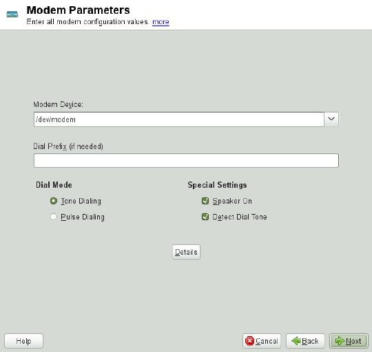
Figure 9.4 Modem Conguration
If you are behind a private branch exchange (PBX), you may need to enter a dial prex.
This is often a zero. Consult the instructions that came with the PBX to nd out. Also
select whether to use tone or pulse dialing, whether the speaker should be on and whether
the modem should wait until it detects a dial tone. The last option should not be enabled
if the modem is connected to an exchange.
Under Details, set the baud rate and the modem initialization strings. Only change these
settings if your modem was not detected automatically or if it requires special settings
for data transmission to work. This is mainly the case with ISDN terminal adapters.
Leave this dialog by clicking OK. To delegate control over the modem to the normal
user without root permissions, activate Enable Device Control for Non-root User via
KInternet. In this way, a user without administrator permissions can activate or deactivate
an interface. Under Dial Prex Regular Expression, specify a regular expression. The
Dial Prex in KInternet, which can be modied by the normal user, must match this
regular expression. If this eld is left empty, the user cannot set a different Dial Prex
without administrator permissions.
Basic Networking 181
In the next dialog, select the ISP. To choose from a predened list of ISPs operating
in your country, select Country. Alternatively, click New to open a dialog in which to
provide the data for your ISP. This includes a name for the dial-up connection and ISP
as well as the login and password provided by your ISP. Enable Always Ask for Password
to be prompted for the password each time you connect.
In the last dialog, specify additional connection options:
Dial on Demand
If you enable Dial on Demand, set at least one name server. Use this feature only
if your Internet connection is inexpensive, because there are programs that period-
ically request data from the Internet.
Modify DNS when Connected
This option is enabled by default, with the effect that the name server address is
updated each time you connect to the Internet.
Automatically Retrieve DNS
If the provider does not transmit its domain name server after connecting, disable
this option and enter the DNS data manually.
Automatically Reconnect
If this options is enabled, the connection is automatically reestablished after failure.
Ignore Prompts
This option disables the detection of any prompts from the dial-up server. If the
connection build-up is slow or does not work at all, try this option.
External Firewall Interface
Selecting this option activates the rewall and sets the interface as external. This
way, you are protected from outside attacks for the duration of your Internet con-
nection.
Idle Time-Out (seconds)
With this option, specify a period of network inactivity after which the modem
disconnects automatically.
IP Details
This opens the address conguration dialog. If your ISP does not assign a dynamic
IP address to your host, disable Dynamic IP Address then enter your host's local
182 Reference

IP address and the remote IP address. Ask your ISP for this information. Leave
Default Route enabled and close the dialog by selecting OK.
Selecting Next returns to the original dialog, which displays a summary of the modem
conguration. Close this dialog with OK.
9.4.3 ISDN
Use this module to congure one or several ISDN cards for your system. If YaST did
not detect your ISDN card, click on Add in the ISDN Devices tab and manually select
your card. Multiple interfaces are possible, but several ISPs can be congured for one
interface. In the subsequent dialogs, set the ISDN options necessary for the proper
functioning of the card.
Figure 9.5 ISDN Conguration
In the next dialog, shown in Figure 9.5, “ISDN Conguration” (page 183), select the
protocol to use. The default is Euro-ISDN (EDSS1), but for older or larger exchanges,
select 1TR6. If you are in the US, select NI1. Select your country in the relevant eld.
The corresponding country code then appears in the eld next to it. Finally, provide
Basic Networking 183
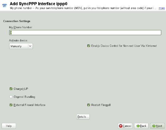
your Area Code and the Dial Prex if necessary. If you do not want to log all your ISDN
trafc, uncheck the Start ISDN Log option.
Activate Device denes how the ISDN interface should be started: At Boot Time causes
the ISDN driver to be initialized each time the system boots. Manually requires you to
load the ISDN driver as root with the command rcisdn start.On Hotplug, used
for PCMCIA or USB devices, loads the driver after the device is plugged in. When
nished with these settings, select OK.
In the next dialog, specify the interface type for your ISDN card and add ISPs to an
existing interface. Interfaces may be either the SyncPPP or the RawIP type, but most
ISPs operate in the SyncPPP mode, which is described below.
Figure 9.6 ISDN Interface Conguration
The number to enter for My Phone Number depends on your particular setup:
ISDN Card Directly Connected to Phone Outlet
A standard ISDN line provides three phone numbers (called multiple subscriber
numbers, or MSNs). If the subscriber asked for more, there may be up to 10. One
of these MSNs must be entered here, but without your area code. If you enter the
184 Reference
wrong number, your phone operator automatically falls back to the rst MSN as-
signed to your ISDN line.
ISDN Card Connected to a Private Branch Exchange
Again, the conguration may vary depending on the equipment installed:
1. Smaller private branch exchanges (PBX) built for home purposes mostly use the
Euro-ISDN (EDSS1) protocol for internal calls. These exchanges have an internal
S0 bus and use internal numbers for the equipment connected to them.
Use one of the internal numbers as your MSN. You should be able to use at least
one of the exchange's MSNs that have been enabled for direct outward dialing.
If this does not work, try a single zero. For further information, consult the doc-
umentation delivered with your phone exchange.
2. Larger phone exchanges designed for businesses normally use the 1TR6 protocol
for internal calls. Their MSN is called EAZ and usually corresponds to the direct-
dial number. For the conguration under Linux, it should be sufcient to enter
the last digit of the EAZ. As a last resort, try each of the digits from 1 to 9.
For the connection to be terminated just before the next charge unit is due, enable
ChargeHUP. However, remember that may not work with every ISP. You can also
enable channel bundling (multilink PPP) by selecting the corresponding option. Finally,
you can enable the rewall for your link by selecting External Firewall Interface and
Restart Firewall. To enable the normal user without administrator permissions to activate
or deactivate the interface, select the Enable Device Control for Non-root User via
KInternet.
Details opens a dialog in which to implement more complex connection schemes which
are not relevant for normal home users. Leave the Details dialog by selecting OK.
In the next dialog, congure IP address settings. If you have not been given a static IP
by your provider, select Dynamic IP Address. Otherwise, use the elds provided to
enter your host's local IP address and the remote IP address according to the specica-
tions of your ISP. If the interface should be the default route to the Internet, select Default
Route. Each host can only have one interface congured as the default route. Leave
this dialog by selecting Next.
The following dialog allows you to set your country and select an ISP. The ISPs included
in the list are call-by-call providers only. If your ISP is not in the list, select New. This
opens the Provider Parameters dialog in which to enter all the details for your ISP.
Basic Networking 185
When entering the phone number, do not include any blanks or commas among the
digits. Finally, enter your login and the password as provided by the ISP. When nished,
select Next.
To use Dial on Demand on a stand-alone workstation, specify the name server (DNS
server) as well. Most ISPs support dynamic DNS, which means the IP address of a
name server is sent by the ISP each time you connect. For a single workstation, however,
you still need to provide a placeholder address like 192.168.22.99. If your ISP
does not support dynamic DNS, specify the name server IP addresses of the ISP. If
desired, specify a time-out for the connection—the period of network inactivity (in
seconds) after which the connection should be automatically terminated. Conrm your
settings with Next. YaST displays a summary of the congured interfaces. To activate
these settings, select OK.
9.4.4 Cable Modem
In some countries it is quite common to access the Internet through the TV cable net-
work. The TV cable subscriber usually gets a modem that is connected to the TV cable
outlet on one side and to a computer network card on the other (using a 10Base-TG
twisted pair cable). The cable modem then provides a dedicated Internet connection
with a xed IP address.
Depending on the instructions provided by your ISP, when conguring the network
card either select Dynamic Address or Statically Assigned IP Address. Most providers
today use DHCP. A static IP address often comes as part of a special business account.
9.4.5 DSL
To congure your DSL device, select the DSL module from the YaST Network Devices
section. This YaST module consists of several dialogs in which to set the parameters
of DSL links based on one of the following protocols:
• PPP over Ethernet (PPPoE)
• PPP over ATM (PPPoATM)
• CAPI for ADSL (Fritz Cards)
186 Reference

• Point-to-Point Tunneling Protocol (PPTP)—Austria
In the DSL Devices tab of the DSL Conguration Overview dialog, you will nd a list
of installed DSL devices. To change the conguration of a DSL device, select it in the
list and click Edit. If you click Add, you can manually congure a new DSL device.
The conguration of a DSL connection based on PPPoE or PPTP requires that the
corresponding network card be set up in the correct way. If you have not done so yet,
rst congure the card by selecting Congure Network Cards (see Section 9.4.1,
“Conguring the Network Card with YaST” (page 169)). In the case of a DSL link,
addresses may be assigned automatically but not via DHCP, which is why you should
not enable the option Dynamic Address. Instead, enter a static dummy address for the
interface, such as 192.168.22.1. In Subnet Mask, enter 255.255.255.0. If you
are conguring a stand-alone workstation, leave Default Gateway empty.
TIP
Values in IP Address and Subnet Mask are only placeholders. They are only
needed to initialize the network card and do not represent the DSL link as such.
In the rst DSL conguration dialog (see Figure 9.7, “DSL Conguration” (page 188)),
select the PPP Mode and the Ethernet Card to which the DSL modem is connected (in
most cases, this is eth0). Then use Activate Device to specify whether the DSL link
should be established during the boot process. Click Enable Device Control for Non-
root User via KInternet to authorize the normal user without root permissions to activate
or deactivate the interface with KInternet.
In the next dialog select your country and choose from a number of ISPs operating in
it. The details of any subsequent dialogs of the DSL conguration depend on the options
set so far, which is why they are only briey mentioned in the following paragraphs.
For details on the available options, read the detailed help available from the dialogs.
Basic Networking 187

Figure 9.7 DSL Conguration
To use Dial on Demand on a stand-alone workstation, also specify the name server
(DNS server). Most ISPs support dynamic DNS—the IP address of a name server is
sent by the ISP each time you connect. For a single workstation, however, provide a
placeholder address like 192.168.22.99. If your ISP does not support dynamic
DNS, enter the name server IP address provided by your ISP.
Idle Time-Out (seconds) denes a period of network inactivity after which to terminate
the connection automatically. A reasonable time-out value is between 60 and 300 sec-
onds. If Dial on Demand is disabled, it may be useful to set the time-out to zero to
prevent automatic hang-up.
The conguration of T-DSL is very similar to the DSL setup. Just select T-Online as
your provider and YaST opens the T-DSL conguration dialog. In this dialog, provide
some additional information required for T-DSL—the line ID, the T-Online number,
the user code and your password. All of these should be included in the information
you received after subscribing to T-DSL.
188 Reference
9.5 NetworkManager
NetworkManager is the ideal solution for laptops and other portable computers. With
NetworkManager, you do not need to worry about conguring network interfaces and
switching between networks when you are moving.
9.5.1 NetworkManager and ifup
However, NetworkManager is not a suitable solution for all cases, so you can still
choose between the traditional method for managing network connections (ifup) and
NetworkManager. If you want to manage your network connection with NetworkMan-
ager, enable NetworkManager in the YaST Network Settings module as described in
Section 21.2, “Enabling NetworkManager” (page 380) and congure your network
connections with NetworkManager. For a list of use cases and a detailed description
how to congure and use NetworkManager, refer to Chapter 21, Using NetworkMan-
ager (page 379).
Some differences between ifup and NetworkManager include:
root Privileges
If you use NetworkManager for network setup, you can easily switch, stop or start
your network connection at any time from within your desktop environment using
an applet. NetworkManager also makes it possible to change and congure wireless
card connections without requiring root privileges. For this reason, NetworkMan-
ager is the ideal solution for a mobile workstation.
Traditional conguration with ifup also provides some ways to switch, stop or start
the connection with or without user intervention, like user-managed devices.
However, this always requires root privileges to change or congure a network
device. This is often a problem for mobile computing, where it is not possible to
precongure all the connection possibilities.
Types of Network Connections
Both traditional conguration and NetworkManager can handle network connections
with a wireless network (with WEP, WPA-PSK, and WPA-Enterprise access) and
wired networks using DHCP and static conguration. They also support connection
through dial-up, DSL and VPN. With NetworkManager you can also connect a
Basic Networking 189
mobile broadband (3G) modem, which is not possible with the traditional congu-
ration.
NetworkManager tries to keep your computer connected at all times using the best
connection available. If the network cable is accidentally disconnected, it tries to
reconnect. It can nd the network with the best signal strength from the list of your
wireless connections and automatically use it to connect. To get the same function-
ality with ifup, a great deal of conguration effort is required.
9.5.2 NetworkManager Functionality and
Conguration Files
The individual network connection settings created with NetworkManager are stored
in conguration proles. The system connections congured with either NetworkMan-
ager or YaST are saved in /etc/networkmanager/system-connections/
*or in /etc/sysconfig/network/ifcfg-*. Any user-dened connections
are stored in GConf for GNOME or $HOME/.kde4/share/apps/
networkmanagement/* for KDE.
In case no prole is congured, NetworkManager automatically creates one and names
it Auto $INTERFACE-NAME. That is made in an attempt to work without any con-
guration for as many cases as (securely) possible. If the automatically created proles
do not suit your needs, use the network connection conguration dialogs provided by
KDE or GNOME to modify them as desired. For more information, refer to Section 21.3,
“Conguring Network Connections” (page 380).
9.5.3 Controlling and Locking Down
NetworkManager Features
On centrally administered machines, certain NetworkManager features can be controlled
or disabled with PolicyKit, for example if a user is allowed to modify administrator
dened connections or if a user is allowed to dene his own network congurations.
To view or change the respective NetworkManager policies, start the graphical Autho-
rizations tool for PolicyKit. In the tree on the left side, nd them below the network-
manager-settings entry.
190 Reference

The following table gives an overview of the PolicyKit identiers related to Network-
Manager:
Table 9.5 PolicyKit Identiers for NetworkManager
DescriptionIdentier
Enable or disable system networkingorg.freedesktop.NetworkManager.enable-
disable-network
Put NetworkManager to sleep or wake
it up
org.freedesktop.NetworkManager.sleep-wake
Enable or disable mobile broadband
devices
org.freedesktop.NetworkManager.enable-
disable-wwan
Allow control of network connectionsorg.freedesktop.NetworkManager.network-
control
Enable or disable WiFi devicesorg.freedesktop.NetworkManager.enable-
disable-wi
Allow use of user-specic connec-
tions
org.freedesktop.NetworkManager.use-user-
connections
Modify system connectionsorg.freedesktop.network-manager-settings.sys-
tem.modify
Connection sharing via an open WiFi
network
org.freedesktop.network-manager-settings.sys-
tem.wi.share.open
Connection sharing via a protected
WiFi network
org.freedesktop.network-manager-settings.sys-
tem.wi.share.protected
Basic Networking 191

9.6 Conguring a Network
Connection Manually
Manual conguration of the network software should always be the last alternative.
Using YaST is recommended. However, this background information about the network
conguration can also assist your work with YaST.
When the Kernel detects a network card and creates a corresponding network interface,
it assigns the device a name depending on the order of device discovery, or order of
the loading of the Kernel modules. The default Kernel device names are only predictable
in very simple or tightly controlled hardware environments. Systems which allow adding
or removing hardware during runtime or support automatic conguration of devices
cannot expect stable network device names assigned by the Kernel across reboots.
However, all system conguration tools rely on persistent interface names. This problem
is solved by udev. The udev persistent net generator (/lib/udev/rules.d/75
-persistent-net-generator.rules) generates a rule matching the hardware
(using its hardware address by default) and assigns a persistently unique interface for
the hardware. The udev database of network interfaces is stored in the le /etc/
udev/rules.d/70-persistent-net.rules. Every line in the le describes
one network interface and species its persistent name. System administrators can
change the assigned names by editing the NAME="" entries. The persistent rules can
also be modied using YaST.
Table 9.6, “Manual Network Conguration Scripts” (page 192) summarizes the most
important scripts involved in the network conguration.
Table 9.6 Manual Network Conguration Scripts
FunctionCommand
The if scripts start or stop network interfaces, or return the status
of the specied interface. For more information, see the ifup
manual page.
ifup,
ifdown,
ifstatus
The rcnetwork script can be used to start, stop or restart all
network interfaces (or just a specied one). Use rcnetwork
rcnetwork
192 Reference

FunctionCommand
stop to stop, rcnetwork start to start and rcnetwork
restart to restart network interfaces. If you want to stop, start
or restart just one interface, use the command followed by the in-
terface name, for example rcnetwork restart eth0. The
rcnetwork status command displays the state of the inter-
faces, their IP addresses and whether a DHCP client is running.
With rcnetwork stop-all-dhcp-clients and
rcnetwork restart-all-dhcp-clients you can stop
or restart DHCP clients running on network interfaces.
For more information about udev and persistent device names, see Chapter 8, Dynamic
Kernel Device Management with udev (page 135).
9.6.1 Conguration Files
This section provides an overview of the network conguration les and explains their
purpose and the format used.
9.6.1.1 /etc/syscong/network/ifcfg-*
These les contain the congurations for network interfaces. They include information
such as the start mode and the IP address. Possible parameters are described in the
manual page of ifup. Additionally, most variables from the dhcp and wireless
les can be used in the ifcfg-* les if a general setting should be used for only one
interface. However, most of the /etc/sysconfig/network/config variables
are global and cannot be overridden in ifcfg-les. For example NETWORKMANAGER
or NETCONFIG_* variables are global.
For ifcfg.template, see Section 9.6.1.2, “/etc/sysconfig/network/
config,/etc/sysconfig/network/dhcp, and /etc/sysconfig/
network/wireless” (page 194).
Basic Networking 193
9.6.1.2 /etc/syscong/network/cong,
/etc/syscong/network/dhcp, and
/etc/syscong/network/wireless
The le config contains general settings for the behavior of ifup,ifdown and
ifstatus.dhcp contains settings for DHCP and wireless for wireless LAN
cards. The variables in all three conguration les are commented. Some of the variables
from /etc/sysconfig/network/config can also be used in ifcfg-* les,
where they are given a higher priority. The /etc/sysconfig/network/ifcfg
.template le lists variables that can be specied in a per interface scope. However,
most of the /etc/sysconfig/network/config variables are global and cannot
be overridden in ifcfg-les. For example, NETWORKMANAGER or NETCONFIG_*
variables are global.
9.6.1.3 /etc/syscong/network/routes and
/etc/syscong/network/ifroute-*
The static routing of TCP/IP packets is determined here. All the static routes required
by the various system tasks can be entered in the /etc/sysconfig/network/
routes le: routes to a host, routes to a host via a gateway and routes to a network.
For each interface that needs individual routing, dene an additional conguration le:
/etc/sysconfig/network/ifroute-*. Replace *with the name of the inter-
face. The entries in the routing conguration les look like this:
# Destination Dummy/Gateway Netmask Device
#
127.0.0.0 0.0.0.0 255.255.255.0 lo
204.127.235.0 0.0.0.0 255.255.255.0 eth0
default 204.127.235.41 0.0.0.0 eth0
207.68.156.51 207.68.145.45 255.255.255.255 eth1
192.168.0.0 207.68.156.51 255.255.0.0 eth1
The route's destination is in the rst column. This column may contain the IP address
of a network or host or, in the case of reachable name servers, the fully qualied network
or hostname.
The second column contains the default gateway or a gateway through which a host or
network can be accessed. The third column contains the netmask for networks or hosts
194 Reference
behind a gateway. For example, the mask is 255.255.255.255 for a host behind a
gateway.
The fourth column is only relevant for networks connected to the local host such as
loopback, Ethernet, ISDN, PPP and dummy device. The device name must be entered
here.
An (optional) fth column can be used to specify the type of a route. Columns that are
not needed should contain a minus sign -to ensure that the parser correctly interprets
the command. For details, refer to the routes(5) man page.
The unied format for IPv4 and IPv6 now looks as follows:
prefix/length gateway - [interface]
And the so-called compatibility format looks accordingly:
prefix gateway length [interface]
For IPv4 you still can use the old format with netmask:
ipv4-network gateway ipv4-netmask [interface]
The following examples are equivalent:
2001:db8:abba:cafe::/64 2001:db8:abba:cafe::dead - eth0
208.77.188.0/24 208.77.188.166 - eth0
2001:db8:abba:cafe:: 2001:db8:abba:cafe::dead 64 eth0
208.77.188.0 208.77.188.166 24 eth0
208.77.188.0 208.77.188.166 255.255.255.0 eth0
9.6.1.4 /etc/resolv.conf
The domain to which the host belongs is specied in this le (keyword search). Also
listed is the status of the name server address to access (keyword nameserver).
Multiple domain names can be specied in the le. When resolving a name that is not
fully qualied, an attempt is made to generate one by attaching the individual search
entries. Multiple name servers can be specied in multiple lines, each beginning with
nameserver. Comments are preceded by #signs. Example 9.5, “/etc/resolv
.conf” (page 196) shows what /etc/resolv.conf could look like.
Basic Networking 195
However, the /etc/resolv.conf should not be edited by hand. Instead, it is gen-
erated by the netconfig script. To dene static DNS conguration without using
YaST, edit the appropriate variables manually in the /etc/sysconfig/network/
config le:
NETCONFIG_DNS_STATIC_SEARCHLIST
list of DNS domain names used for hostname lookup
NETCONFIG_DNS_STATIC_SERVERS
list of name server IP addresses to use for hostname lookup
NETCONFIG_DNS_FORWARDER
denes the name of the DNS forwarder that has to be congured
To disable DNS conguration using netcong, set NETCONFIG_DNS_POLICY=''.
For more information about netconfig, see man 8 netconfig.
Example 9.5 /etc/resolv.conf
# Our domain
search example.com
#
# We use dns.example.com (192.168.1.116) as nameserver
nameserver 192.168.1.116
9.6.1.5 /sbin/netcong
netconfig is a modular tool to manage additional network conguration settings. It
merges statically dened settings with settings provided by autoconguration mecha-
nisms as DHCP or PPP according to a predened policy. The required changes are ap-
plied to the system by calling the netcong modules that are responsible for modifying
a conguration le and restarting a service or a similar action.
netconfig recognizes three main actions. The netconfig modify and
netconfig remove commands are used by daemons such as DHCP or PPP to
provide or remove settings to netcong. Only the netconfig update command
is available for the user:
modify
The netconfig modify command modies the current interface and service
specic dynamic settings and updates the network conguration. Netcong reads
196 Reference
settings from standard input or from a le specied with the --lease-file
filename option and internally stores them until a system reboot (or the next
modify or remove action). Already existing settings for the same interface and
service combination are overwritten. The interface is specied by the -i
interface_name parameter. The service is specied by the -s
service_name parameter.
remove
The netconfig remove command removes the dynamic settings provided by
a modicatory action for the specied interface and service combination and updates
the network conguration. The interface is specied by the -i interface_name
parameter. The service is specied by the -s service_name parameter.
update
The netconfig update command updates the network conguration using
current settings. This is useful when the policy or the static conguration has
changed. Use the -m module_type parameter, if you want to update a specied
service only (dns,nis, or ntp).
The netcong policy and the static conguration settings are dened either manually
or using YaST in the /etc/sysconfig/network/config le. The dynamic
conguration settings provided by autoconguration tools as DHCP or PPP are delivered
directly by these tools with the netconfig modify and netconfig remove
actions. NetworkManager also uses netconfig modify and netconfig remove
actions. When NetworkManager is enabled, netcong (in policy mode auto) uses
only NetworkManager settings, ignoring settings from any other interfaces congured
using the traditional ifup method. If NetworkManager does not provide any setting,
static settings are used as a fallback. A mixed usage of NetworkManager and the tradi-
tional ifup method is not supported.
For more information about netconfig, see man 8 netconfig.
9.6.1.6 /etc/hosts
In this le, shown in Example 9.6, “/etc/hosts” (page 198), IP addresses are assigned
to hostnames. If no name server is implemented, all hosts to which an IP connection
will be set up must be listed here. For each host, enter a line consisting of the IP address,
the fully qualied hostname, and the hostname into the le. The IP address must be at
Basic Networking 197

the beginning of the line and the entries separated by blanks and tabs. Comments are
always preceded by the #sign.
Example 9.6 /etc/hosts
127.0.0.1 localhost
192.168.2.100 jupiter.example.com jupiter
192.168.2.101 venus.example.com venus
9.6.1.7 /etc/networks
Here, network names are converted to network addresses. The format is similar to that
of the hosts le, except the network names precede the addresses. See Example 9.7,
“/etc/networks” (page 198).
Example 9.7 /etc/networks
loopback 127.0.0.0
localnet 192.168.0.0
9.6.1.8 /etc/host.conf
Name resolution—the translation of host and network names via the resolver library—is
controlled by this le. This le is only used for programs linked to libc4 or libc5. For
current glibc programs, refer to the settings in /etc/nsswitch.conf. A parameter
must always stand alone in its own line. Comments are preceded by a #sign. Table 9.7,
“Parameters for /etc/host.conf” (page 198) shows the parameters available. A sample
/etc/host.conf is shown in Example 9.8, “/etc/host.conf” (page 199).
Table 9.7 Parameters for /etc/host.conf
Species in which order the services are accessed for the name
resolution. Available arguments are (separated by blank spaces
or commas):
order hosts,bind
hosts: searches the /etc/hosts le
bind: accesses a name server
nis: uses NIS
198 Reference

Denes if a host entered in /etc/hosts can have multiple
IP addresses.
multi on/off
These parameters inuence the name server spoong but do
not exert any inuence on the network conguration.
nospoof on
spoofalert on/off
The specied domain name is separated from the hostname
after hostname resolution (as long as the hostname includes
trim domainname
the domain name). This option is useful only if names from
the local domain are in the /etc/hosts le, but should still
be recognized with the attached domain names.
Example 9.8 /etc/host.conf
# We have named running
order hosts bind
# Allow multiple address
multi on
9.6.1.9 /etc/nsswitch.conf
The introduction of the GNU C Library 2.0 was accompanied by the introduction of
the Name Service Switch (NSS). Refer to the nsswitch.conf(5) man page and
The GNU C Library Reference Manual for details.
The order for queries is dened in the le /etc/nsswitch.conf. A sample
nsswitch.conf is shown in Example 9.9, “/etc/nsswitch.conf” (page 200).
Comments are preceded by #signs. In this example, the entry under the hosts database
means that a request is sent to /etc/hosts (files) via DNS.
Basic Networking 199

Example 9.9 /etc/nsswitch.conf
passwd: compat
group: compat
hosts: files dns
networks: files dns
services: db files
protocols: db files
rpc: files
ethers: files
netmasks: files
netgroup: files nis
publickey: files
bootparams: files
automount: files nis
aliases: files nis
shadow: compat
The “databases” available over NSS are listed in Table 9.8, “Databases Available via
/etc/nsswitch.conf” (page 200). The conguration options for NSS databases are listed
in Table 9.9, “Conguration Options for NSS “Databases”” (page 201).
Table 9.8 Databases Available via /etc/nsswitch.conf
Mail aliases implemented by sendmail; see man 5
aliases.
aliases
Ethernet addresses.
ethers
List of network and their subnet masks. Only needed, if
you use subnetting.
netmasks
For user groups used by getgrent. See also the man page
for group.
group
For hostnames and IP addresses, used by
gethostbyname and similar functions.
hosts
Valid host and user lists in the network for the purpose of
controlling access permissions; see the netgroup(5)
man page.
netgroup
200 Reference

Network names and addresses, used by getnetent.networks
Public and secret keys for Secure_RPC used by NFS and
NIS+..
publickey
User passwords, used by getpwent; see the passwd(5)
man page.
passwd
Network protocols, used by getprotoent; see the
protocols(5) man page.
protocols
Remote procedure call names and addresses, used by
getrpcbyname and similar functions.
rpc
Network services, used by getservent.services
Shadow passwords of users, used by getspnam; see the
shadow(5) man page.
shadow
Table 9.9 Conguration Options for NSS “Databases”
directly access les, for example, /etc/aliasesfiles
access via a database
db
NIS, see also Chapter 3, Using NIS (↑Security Guide)
nis,nisplus
can only be used as an extension for hosts and
networks
dns
can only be used as an extension for passwd,shadow
and group
compat
9.6.1.10 /etc/nscd.conf
This le is used to congure nscd (name service cache daemon). See the nscd(8)
and nscd.conf(5) man pages. By default, the system entries of passwd and
Basic Networking 201
groups are cached by nscd. This is important for the performance of directory services,
like NIS and LDAP, because otherwise the network connection needs to be used for
every access to names or groups. hosts is not cached by default, because the mecha-
nism in nscd to cache hosts makes the local system unable to trust forward and reverse
lookup checks. Instead of asking nscd to cache names, set up a caching DNS server.
If the caching for passwd is activated, it usually takes about fteen seconds until a
newly added local user is recognized. Reduce this waiting time by restarting nscd with
the command rcnscd restart.
9.6.1.11 /etc/HOSTNAME
This contains the fully qualied hostname with the domain name attached. This le is
read by several scripts while the machine is booting. It must contain only one line (in
which the hostname is set).
9.6.2 Testing the Conguration
Before you write your conguration to the conguration les, you can test it. To set
up a test conguration, use the ip command. To test the connection, use the ping
command. Older conguration tools, ifconfig and route, are also available.
The commands ip,ifconfig and route change the network conguration directly
without saving it in the conguration le. Unless you enter your conguration in the
correct conguration les, the changed network conguration is lost on reboot.
9.6.2.1 Conguring a Network Interface with ip
ip is a tool to show and congure network devices, routing, policy routing, and tunnels.
ip is a very complex tool. Its common syntax is ip options object command.
You can work with the following objects:
link
This object represents a network device.
address
This object represents the IP address of device.
202 Reference
neighbor
This object represents a ARP or NDISC cache entry.
route
This object represents the routing table entry.
rule
This object represents a rule in the routing policy database.
maddress
This object represents a multicast address.
mroute
This object represents a multicast routing cache entry.
tunnel
This object represents a tunnel over IP.
If no command is given, the default command is used (usually list).
Change the state of a device with the command ip link
set device_name command. For example, to deactivate device eth0, enter ip
link set eth0 down. To activate it again, use ip link set eth0 up.
After activating a device, you can congure it. To set the IP address, use ip addr
add ip_address + dev device_name. For example, to set the address of the
interface eth0 to 192.168.12.154/30 with standard broadcast (option brd), enter ip
addr add 192.168.12.154/30 brd + dev eth0.
To have a working connection, you must also congure the default gateway. To set a
gateway for your system, enter ip route add gateway_ip_address. To
translate one IP address to another, use nat:ip route add
nat ip_address via other_ip_address.
To display all devices, use ip link ls. To display the running interfaces only, use
ip link ls up. To print interface statistics for a device, enter ip -s link
ls device_name. To view addresses of your devices, enter ip addr. In the output
of the ip addr, also nd information about MAC addresses of your devices. To show
all routes, use ip route show.
Basic Networking 203
For more information about using ip, enter ip help or see the ip(8) man page.
The help option is also available for all ip subcommands. If, for example, you need
help for ip addr, enter ip addr help. Find the ip manual in /usr/share/
doc/packages/iproute2/ip-cref.pdf.
9.6.2.2 Testing a Connection with ping
The ping command is the standard tool for testing whether a TCP/IP connection works.
It uses the ICMP protocol to send a small data packet, ECHO_REQUEST datagram,
to the destination host, requesting an immediate reply. If this works, ping displays a
message to that effect, which indicates that the network link is basically functioning.
ping does more than only test the function of the connection between two computers:
it also provides some basic information about the quality of the connection. In Exam-
ple 9.10, “Output of the Command ping” (page 204), you can see an example of the
ping output. The second-to-last line contains information about the number of trans-
mitted packets, packet loss, and total time of ping running.
As the destination, you can use a hostname or IP address, for example,
ping example.com or ping 192.168.3.100. The program sends packets until
you press Ctrl +C.
If you only need to check the functionality of the connection, you can limit the number
of the packets with the -c option. For example to limit ping to three packets, enter
ping -c 3 example.com.
Example 9.10 Output of the Command ping
ping -c 3 example.com
PING example.com (192.168.3.100) 56(84) bytes of data.
64 bytes from example.com (192.168.3.100): icmp_seq=1 ttl=49 time=188 ms
64 bytes from example.com (192.168.3.100): icmp_seq=2 ttl=49 time=184 ms
64 bytes from example.com (192.168.3.100): icmp_seq=3 ttl=49 time=183 ms
--- example.com ping statistics ---
3 packets transmitted, 3 received, 0% packet loss, time 2007ms
rtt min/avg/max/mdev = 183.417/185.447/188.259/2.052 ms
The default interval between two packets is one second. To change the interval, ping
provides the option -i. For example, to increase the ping interval to ten seconds, enter
ping -i 10 example.com.
204 Reference

In a system with multiple network devices, it is sometimes useful to send the ping
through a specic interface address. To do so, use the -I option with the name of the
selected device, for example, ping -I wlan1 example.com.
For more options and information about using ping, enter ping -h or see the ping
(8) man page.
TIP: Pinging IPv6 Addresses
For IPv6 addresses use the ping6 command. Note, to ping link-local addresses,
you must specify the interface with -I. The following command works, if the
address is reachable via eth1:
ping6 -I eth1 fe80::117:21ff:feda:a425
9.6.2.3 Conguring the Network with ifcong
ifconfig is a network conguration tool.
NOTE: ifconfig and ip
The ifconfig tool is obsolete. Use ip instead. In contrast to ip, you can use
ifconfig only for interface conguration. It limits interface names to 9
characters.
Without arguments, ifconfig displays the status of the currently active interfaces.
As you can see in Example 9.11, “Output of the ifconfig Command” (page 206),
ifconfig has very well-arranged and detailed output. The output also contains infor-
mation about the MAC address of your device (the value of HWaddr) in the rst line.
Basic Networking 205

Example 9.11 Output of the ifcong Command
eth0 Link encap:Ethernet HWaddr 00:08:74:98:ED:51
inet6 addr: fe80::208:74ff:fe98:ed51/64 Scope:Link
UP BROADCAST MULTICAST MTU:1500 Metric:1
RX packets:634735 errors:0 dropped:0 overruns:4 frame:0
TX packets:154779 errors:0 dropped:0 overruns:0 carrier:1
collisions:0 txqueuelen:1000
RX bytes:162531992 (155.0 Mb) TX bytes:49575995 (47.2 Mb)
Interrupt:11 Base address:0xec80
lo Link encap:Local Loopback
inet addr:127.0.0.1 Mask:255.0.0.0
inet6 addr: ::1/128 Scope:Host
UP LOOPBACK RUNNING MTU:16436 Metric:1
RX packets:8559 errors:0 dropped:0 overruns:0 frame:0
TX packets:8559 errors:0 dropped:0 overruns:0 carrier:0
collisions:0 txqueuelen:0
RX bytes:533234 (520.7 Kb) TX bytes:533234 (520.7 Kb)
wlan1 Link encap:Ethernet HWaddr 00:0E:2E:52:3B:1D
inet addr:192.168.2.4 Bcast:192.168.2.255 Mask:255.255.255.0
inet6 addr: fe80::20e:2eff:fe52:3b1d/64 Scope:Link
UP BROADCAST NOTRAILERS RUNNING MULTICAST MTU:1500 Metric:1
RX packets:50828 errors:0 dropped:0 overruns:0 frame:0
TX packets:43770 errors:0 dropped:0 overruns:0 carrier:0
collisions:0 txqueuelen:1000
RX bytes:45978185 (43.8 Mb) TX bytes:7526693 (7.1 MB)
For more options and information about using ifconfig, enter ifconfig -h or
see the ifconfig (8) man page.
9.6.2.4 Conguring Routing with route
route is a program for manipulating the IP routing table. You can use it to view your
routing conguration and to add or remove routes.
NOTE: route and ip
The program route is obsolete. Use ip instead.
route is especially useful if you need quick and comprehensible information about
your routing conguration to determine problems with routing. To view your current
routing conguration, enter route -n as root.
206 Reference

Example 9.12 Output of the route -n Command
route -n
Kernel IP routing table
Destination Gateway Genmask Flags MSS Window irtt Iface
10.20.0.0 * 255.255.248.0 U 0 0 0 eth0
link-local * 255.255.0.0 U 0 0 0 eth0
loopback * 255.0.0.0 U 0 0 0 lo
default styx.exam.com 0.0.0.0 UG 0 0 0 eth0
For more options and information about using route, enter route -h or see the route
(8) man page.
9.6.3 Start-Up Scripts
Apart from the conguration les described above, there are also various scripts that
load the network programs while the machine is booting. These are started as soon as
the system is switched to one of the multiuser runlevels. Some of these scripts are de-
scribed in Table 9.10, “Some Start-Up Scripts for Network Programs” (page 207).
Table 9.10 Some Start-Up Scripts for Network Programs
This script handles the conguration of the net-
work interfaces. If the network service was not
started, no network interfaces are implemented.
/etc/init.d/network
Starts xinetd. xinetd can be used to make server
services available on the system. For example, it
/etc/init.d/xinetd
can start vsftpd whenever an FTP connection is
initiated.
Starts the rpcbind utility that converts RPC pro-
gram numbers to universal addresses. It is needed
for RPC services, such as an NFS server.
/etc/init.d/rpcbind
Starts the NFS server.
/etc/init.d/nfsserver
Controls the postx process.
/etc/init.d/postfix
Starts the NIS server.
/etc/init.d/ypserv
Basic Networking 207

Starts the NIS client.
/etc/init.d/ypbind
9.7 smpppd as Dial-up Assistant
Some home users do not have a dedicated line connecting them to the Internet. Instead,
they use dial-up connections. Depending on the dial-up method (ISDN or DSL), the
connection is controlled by ipppd or pppd. Basically, all that needs to be done to go
online is to start these programs correctly.
If you have a at-rate connection that does not generate any additional costs for the
dial-up connection, simply start the respective daemon. Control the dial-up connection
with a desktop applet or a command-line interface. If the Internet gateway is not the
host you are using, you might want to control the dial-up connection by way of a network
host.
This is where smpppd (SUSE Meta PPP Daemon) is involved. It provides a uniform
interface for auxiliary programs and acts in two directions. First, it programs the required
pppd or ipppd and controls its dial-up properties. Second, it makes various providers
available to the user programs and transmits information about the current status of the
connection. As smpppd can also be controlled by way of the network, it is suitable for
controlling dial-up connections to the Internet from a workstation in a private subnet-
work.
9.7.1 Conguring smpppd
The connections provided by smpppd are automatically congured by YaST. The actual
dial-up programs KInternet and cinternet are also precongured. Manual settings are
only required to congure additional features of smpppd such as remote control.
The conguration le of smpppd is /etc/smpppd.conf. By default, it does not
enable remote control. The most important options of this conguration le are:
open-inet-socket = yes|no
To control smpppd via the network, set this option to yes. smpppd listens on port
3185. If this parameter is set to yes, the parameters bind-address,
host-range and password must be set accordingly.
208 Reference
bind-address = ip address
If a host has several IP addresses, use this parameter to determine at which IP ad-
dress smpppd should accept connections. The default is to listen at all addresses.
host-range = min ipmax ip
The parameter host-range denes a network range. Hosts whose IP addresses
are within this range are granted access to smpppd. All hosts not within this range
are denied access.
password = password
By assigning a password, limit the clients to authorized hosts. As this is a plain-
text password, you should not overrate the security it provides. If no password is
assigned, all clients are permitted to access smpppd.
slp-register = yes|no
With this parameter, the smpppd service can be announced in the network via SLP.
More information about smpppd is available in the smpppd(8) and
smpppd.conf(5) man pages.
9.7.2 Conguring qinternet for Remote Use
qinternet can be used to control a local or remote smpppd. cinternet is the command-
line counterpart to the graphical KInternet. To prepare these utilities for use with a remote
smpppd, edit the conguration le /etc/smpppd-c.conf manually or using qin-
ternet. This le only uses four options:
sites = list of sites
list of sites where the front-ends search for smpppd. The front-ends test
the options in the order specied here. local orders the establishment of a con-
nection to the local smpppd. gateway points to an smpppd on the gateway.
config-file indicates that the connection should be established to the smpppd
specied in the server and port options in /etc/smpppd-c.conf.slp
orders the front-ends to connect to an smpppd found via SLP.
server = server
The host on which smpppd runs.
Basic Networking 209
port = port
The port on which smpppd runs.
password = password
The password selected for smpppd.
210 Reference

10
SLP Services in the Network
The service location protocol (SLP) was developed to simplify the conguration of
networked clients within a local network. To congure a network client, including all
required services, the administrator traditionally needs detailed knowledge of the servers
available in the network. SLP makes the availability of selected services known to all
clients in the local network. Applications that support SLP can use the information
distributed and be congured automatically.
openSUSE® supports installation using installation sources provided with SLP and
contains many system services with integrated support for SLP. YaST and Konqueror
both have appropriate front-ends for SLP. You can use SLP to provide networked clients
with central functions, such as an installation server, le server, or print server on your
system.
IMPORTANT: SLP Support in openSUSE
Services that offer SLP support include cupsd, rsyncd, ypserv, openldap2, ksys-
guardd, saned, kdm, vnc, login, smpppd, rpasswd , postx, and sshd (via sh).
10.1 Installation
All packages necessary to use SLP services are installed by default. However, if you
want to provide services via SLP, check that the openslp-server package is in-
stalled. For SLP daemon server conguration install the yast2-slp-server
package.
SLP Services in the Network 211
10.2 Activating SLP
slpd must run on your system to offer services with SLP. If the machine should only
operate as client, and does not offer services, it is not necessary to run slpd. Like most
system services in openSUSE, the slpd daemon is controlled by means of a separate
init script. After the installation, the daemon is inactive by default. To activate it
temporarily, run rcslpd start as root or rcslpd stop to stop it. Perform a
restart or status check with restart or status. If slpd should be always active after
booting, enable slpd in YaST System >System Services (Runlevel) or run the
insserv slpd command as root.
10.3 SLP Front-Ends in openSUSE
To nd services provided via SLP in your network, use an SLP front-end such as
slptool (openslp package) or YaST:
slptool
slptool is a command line program that can be used to announce SLP inquiries in
the network or announce proprietary services. slptool --help lists all available
options and functions. For example, to nd all time servers that announce themselves
in the current network, run the command:
slptool findsrvs service:ntp
YaST
YaST also provides an SLP browser. However, this browser is not available from
the YaST Control Center. To start it, run yast2 slp as root user. Click on a
Service Type on the lefthand side to get more information about a service.
10.4 Installation over SLP
If you have an installation server with openSUSE installation media within your network,
this can be registered and offered with SLP. For details, see Section 2.2, “Setting Up
the Server Holding the Installation Sources” (page 46). If SLP installation is selected,
linuxrc starts an SLP inquiry after the system has booted from the selected boot medium
and displays the sources found.
212 Reference
10.5 Providing Services via SLP
Many applications in openSUSE have integrated SLP support through the use of the
libslp library. If a service has not been compiled with SLP support, use one of the
following methods to make it available via SLP:
Static Registration with /etc/slp.reg.d
Create a separate registration le for each new service. This is an example for
registering a scanner service:
## Register a saned service on this system
## en means english language
## 65535 disables the timeout, so the service registration does
## not need refreshes
service:scanner.sane://$HOSTNAME:6566,en,65535
watch-port-tcp=6566
description=SANE scanner daemon
The most important line in this le is the service URL, which begins with
service:. This contains the service type (scanner.sane) and the address
under which the service is available on the server. $HOSTNAME is automatically
replaced with the full hostname. The name of the TCP port on which the relevant
service can be found follows, separated by a colon. Then enter the language in
which the service should appear and the duration of registration in seconds. These
should be separated from the service URL by commas. Set the value for the duration
of registration between 0and 65535.0prevents registration. 65535 removes all
restrictions.
The registration le also contains the two variables watch-port-tcp and
description.watch-port-tcp links the SLP service announcement to
whether the relevant service is active by having slpd check the status of the service.
The second variable contains a more precise description of the service that is dis-
played in suitable browsers.
Static Registration with /etc/slp.reg
The only difference between this method and the procedure with /etc/slp.reg
.d is that all services are grouped within a central le.
SLP Services in the Network 213
Dynamic Registration with slptool
If a service needs to be registered dynamically without the need of conguration
les, use the slptool command line utility. The same utility can also be used to
deregister an existing service offering without restarting slpd.
10.6 For More Information
RFC 2608, 2609, 2610
RFC 2608 generally deals with the denition of SLP. RFC 2609 deals with the
syntax of the service URLs used in greater detail and RFC 2610 deals with DHCP
via SLP.
http://www.openslp.org
The home page of the OpenSLP project.
/usr/share/doc/packages/openslp
This directory contains the documentation for SLP coming with the
openslp-server package, including a README.SuSE containing the open-
SUSE details, the RFCs, and two introductory HTML documents. Programmers
who want to use the SLP functions nd more information in the Programmers
Guide that is included in the openslp-devel package.
214 Reference
11
The Domain Name System
DNS (domain name system) is needed to resolve the domain names and hostnames into
IP addresses. In this way, the IP address 192.168.2.100 is assigned to the hostname
jupiter, for example. Before setting up your own name server, read the general in-
formation about DNS in Section 9.3, “Name Resolution” (page 167). The following
conguration examples refer to BIND.
11.1 DNS Terminology
Zone
The domain namespace is divided into regions called zones. For instance, if you
have example.com, you have the example section (or zone) of the com domain.
DNS server
The DNS server is a server that maintains the name and IP information for a domain.
You can have a primary DNS server for master zone, a secondary server for slave
zone, or a slave server without any zones for caching.
Master zone DNS server
The master zone includes all hosts from your network and a DNS server master
zone stores up-to-date records for all the hosts in your domain.
Slave zone DNS server
A slave zone is a copy of the master zone. The slave zone DNS server obtains
its zone data with zone transfer operations from its master server. The slave
zone DNS server responds authoritatively for the zone as long as it has valid
The Domain Name System 215
(not expired) zone data. If the slave cannot obtain a new copy of the zone data,
it stops responding for the zone.
Forwarder
Forwarders are DNS servers to which your DNS server should send queries it
cannot answer. To enable different conguration sources in one conguration,
netconfig is used (see also man 8 netconfig).
Record
The record is information about name and IP address. Supported records and their
syntax are described in BIND documentation. Some special records are:
NS record
An NS record tells name servers which machines are in charge of a given do-
main zone.
MX record
The MX (mail exchange) records describe the machines to contact for directing
mail across the Internet.
SOA record
SOA (Start of Authority) record is the rst record in a zone le. The SOA
record is used when using DNS to synchronize data between multiple comput-
ers.
11.2 Installation
To install a DNS server, start YaST and select Software >Software Management.
Choose Filter >Patterns and select DHCP and DNS Server. Conrm the installation
of the dependent packages to nish the installation process.
11.3 Conguration with YaST
Use the YaST DNS module to congure a DNS server for the local network. When
starting the module for the rst time, a wizard starts, prompting you to make a few de-
cisions concerning administration of the server. Completing this initial setup produces
216 Reference

a basic server conguration. Use the expert mode to deal with more advanced congu-
ration tasks, such as setting up ACLs, logging, TSIG keys, and other options.
11.3.1 Wizard Conguration
The wizard consists of three steps or dialogs. At the appropriate places in the dialogs,
you are given the opportunity to enter the expert conguration mode.
1When starting the module for the rst time, the Forwarder Settings dialog, shown
in Figure 11.1, “DNS Server Installation: Forwarder Settings” (page 217), opens.
The Netcong DNS Policy decides which devices should provide forwarders or
whether you want to supply your own Forwarder List. For more information about
netcong, see man 8 netconfig.
Figure 11.1 DNS Server Installation: Forwarder Settings
Forwarders are DNS servers to which your DNS server sends queries it cannot answer
itself. Enter their IP address and click Add.
The Domain Name System 217

2The DNS Zones dialog consists of several parts and is responsible for the management
of zone les, described in Section 11.6, “Zone Files” (page 233). For a new zone,
provide a name for it in Name. To add a reverse zone, the name must end in
.in-addr.arpa. Finally, select the Type (master, slave, or forward). See Fig-
ure 11.2, “DNS Server Installation: DNS Zones” (page 218). Click Edit to congure
other settings of an existing zone. To remove a zone, click Delete.
Figure 11.2 DNS Server Installation: DNS Zones
3In the nal dialog, you can open the DNS port in the rewall by clicking Open Port
in Firewall. Then decide whether to start the DNS server when booting (On or Off).
You can also activate LDAP support. See Figure 11.3, “DNS Server Installation:
Finish Wizard” (page 219).
218 Reference

Figure 11.3 DNS Server Installation: Finish Wizard
11.3.2 Expert Conguration
After starting the module, YaST opens a window displaying several conguration op-
tions. Completing it results in a DNS server conguration with the basic functions in
place:
11.3.2.1 Start-Up
Under Start-Up, dene whether the DNS server should be started when the booting the
system or manually. To start the DNS server immediately, click Start DNS Server Now.
To stop the DNS server, click Stop DNS Server Now. To save the current settings, select
Save Settings and Reload DNS Server Now. You can open the DNS port in the rewall
with Open Port in Firewall and modify the rewall settings with Firewall Details.
By selecting LDAP Support Active, the zone les are managed by an LDAP database.
Any changes to zone data written to the LDAP database are picked up by the DNS
server as soon as it is restarted or prompted to reload its conguration.
The Domain Name System 219
11.3.2.2 Forwarders
If your local DNS server cannot answer a request, it tries to forward the request to a
Forwarder, if congured so. This forwarder may be added manually to the Forwarder
List. If the forwarder is not static like in dial-up connections, netcong handles the
conguration. For more information about netcong, see man 8 netconfig.
11.3.2.3 Basic Options
In this section, set basic server options. From the Option menu, select the desired item
then specify the value in the corresponding entry eld. Include the new entry by selecting
Add.
11.3.2.4 Logging
To set what the DNS server should log and how, select Logging. Under Log Type,
specify where the DNS server should write the log data. Use the systemwide log le
/var/log/messages by selecting System Log or specify a different le by selecting
File. In the latter case, additionally specify a name, the maximum le size in megabytes
and the number of logle versions to store.
Further options are available under Additional Logging. Enabling Log All DNS Queries
causes every query to be logged, in which case the log le could grow extremely large.
For this reason, it is not a good idea to enable this option for other than debugging
purposes. To log the data trafc during zone updates between DHCP and DNS server,
enable Log Zone Updates. To log the data trafc during a zone transfer from master to
slave, enable Log Zone Transfer. See Figure 11.4, “DNS Server: Logging” (page 221).
220 Reference

Figure 11.4 DNS Server: Logging
11.3.2.5 ACLs
Use this dialog to dene ACLs (access control lists) to enforce access restrictions. After
providing a distinct name under Name, specify an IP address (with or without netmask)
under Value in the following fashion:
{ 192.168.1/24; }
The syntax of the conguration le requires that the address ends with a semicolon and
is put into curly braces.
11.3.2.6 TSIG Keys
The main purpose of TSIGs (transaction signatures) is to secure communications between
DHCP and DNS servers. They are described in Section 11.8, “Secure Transactions”
(page 237).
The Domain Name System 221
To generate a TSIG key, enter a distinctive name in the eld labeled Key ID and specify
the le where the key should be stored (Filename). Conrm your choices with Generate.
To use a previously created key, leave the Key ID eld blank and select the le where
it is stored under Filename. After that, conrm with Add.
11.3.2.7 DNS Zones (Adding a Slave Zone)
To add a slave zone, select DNS Zones, choose the zone type Slave, write the name of
the new zone, and click Add.
In the Zone Editor sub-dialog under Master DNS Server IP, specify the master from
which the slave should pull its data. To limit access to the server, select one of the ACLs
from the list.
11.3.2.8 DNS Zones (Adding a Master Zone)
To add a master zone, select DNS Zones, choose the zone type Master, write the name
of the new zone, and click Add. When adding a master zone, a reverse zone is also
needed. For example, when adding the zone example.com that points to hosts in a
subnet 192.168.1.0/24, you should also add a reverse zone for the IP-address
range covered. By denition, this should be named 1.168.192.in-addr.arpa.
11.3.2.9 DNS Zones (Editing a Master Zone)
To edit a master zone, select DNS Zones, select the master zone from the table, and
click Edit. The dialog consists of several pages: Basics (the one opened rst), NS
Records,MX Records,SOA, and Records.
The basic dialog, shown in Figure 11.5, “DNS Server: Zone Editor (Basics)” (page 223),
lets you dene settings for dynamic DNS and access options for zone transfers to clients
and slave name servers. To permit the dynamic updating of zones, select Allow Dynamic
Updates as well as the corresponding TSIG key. The key must have been dened before
the update action starts. To enable zone transfers, select the corresponding ACLs. ACLs
must have been dened already.
In the Basics dialog, select whether to enable zone transfers. Use the listed ACLs to
dene who can download zones.
222 Reference
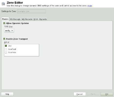
Figure 11.5 DNS Server: Zone Editor (Basics)
Zone Editor (NS Records)
The NS Records dialog allows you to dene alternative name servers for the zones
specied. Make sure that your own name server is included in the list. To add a
record, enter its name under Name Server to Add then conrm with Add. See Fig-
ure 11.6, “DNS Server: Zone Editor (NS Records)” (page 224).
The Domain Name System 223
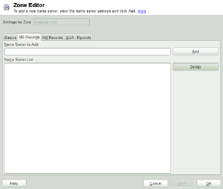
Figure 11.6 DNS Server: Zone Editor (NS Records)
Zone Editor (MX Records)
To add a mail server for the current zone to the existing list, enter the corresponding
address and priority value. After doing so, conrm by selecting Add. See Fig-
ure 11.7, “DNS Server: Zone Editor (MX Records)” (page 225).
224 Reference


Figure 11.8 DNS Server: Zone Editor (SOA)
Zone Editor (Records)
This dialog manages name resolution. In Record Key, enter the hostname then select
its type. A-Record represents the main entry. The value for this should be an IP
address. CNAME is an alias. Use the types NS and MX for detailed or partial records
that expand on the information provided in the NS Records and MX Records tabs.
These three types resolve to an existing A record. PTR is for reverse zones. It is
the opposite of an Arecord, for example:
hostname.example.com. IN A 192.168.0.1
1.0.168.192.in-addr.arpa IN PTR hostname.example.com.
NOTE: Editing the Reverse Zone
After adding a forward zone, go back to the main menu and select the reverse
zone for editing. There in the tab Basics activate the checkbox Automatically
Generate Records From and select your forward zone. That way, all changes to
the forward zone are automatically updated in the reverse zone.
226 Reference

11.4 Starting the BIND Name Server
On a openSUSE® system, the name server BIND (Berkeley Internet Name Domain)
comes precongured so it can be started right after installation without any problems.
If you already have a functioning Internet connection and have entered 127.0.0.1
as the name server address for localhost in /etc/resolv.conf, you normally
already have a working name resolution without needing to know the DNS of the
provider. BIND carries out name resolution via the root name server, a notably slower
process. Normally, the DNS of the provider should be entered with its IP address in the
conguration le /etc/named.conf under forwarders to ensure effective and
secure name resolution. If this works so far, the name server runs as a pure caching-
only name server. Only when you congure its own zones it becomes a proper DNS.
Find a simple example documented in /usr/share/doc/packages/bind/
config.
TIP: Automatic Adaptation of the Name Server Information
Depending on the type of Internet connection or the network connection, the
name server information can automatically be adapted to the current conditions.
To do this, set the NETCONFIG_DNS_POLICY variable in the /etc/
sysconfig/network/config le to auto.
However, do not set up an ofcial domain until one is assigned to you by the responsible
institution. Even if you have your own domain and it is managed by the provider, you
are better off not using it, because BIND would otherwise not forward requests for this
domain. The Web server at the provider, for example, would not be accessible for this
domain.
To start the name server, enter the command rcnamed start as root. If “done”
appears to the right in green then named (as the name server process is called) has been
started successfully. Test the name server immediately on the local system with the
host or dig programs, which should return localhost as the default server with
the address 127.0.0.1. If this is not the case, /etc/resolv.conf probably
contains an incorrect name server entry or the le does not exist at all. For the rst test,
enter host 127.0.0.1, which should always work. If you get an error message, use
rcnamed status to see whether the server is actually running. If the name server
does not start or behaves unexpectedly, you can usually nd the cause in the log le
/var/log/messages.
The Domain Name System 227
To use the name server of the provider (or one already running on your network) as the
forwarder, enter the corresponding IP address or addresses in the options section
under forwarders. The addresses included in Example 11.1, “Forwarding Options
in named.conf” (page 228) are just examples. Adjust these entries to your own setup.
Example 11.1 Forwarding Options in named.conf
options {
directory "/var/lib/named";
forwarders { 10.11.12.13; 10.11.12.14; };
listen-on { 127.0.0.1; 192.168.1.116; };
allow-query { 127/8; 192.168/16 };
notify no;
};
The options entry is followed by entries for the zone, localhost, and
0.0.127.in-addr.arpa. The type hint entry under “.” should always be
present. The corresponding les do not need to be modied and should work as they
are. Also make sure that each entry is closed with a “;” and that the curly braces are in
the correct places. After changing the conguration le /etc/named.conf or the
zone les, tell BIND to reread them with rcnamed reload. Achieve the same by
stopping and restarting the name server with rcnamed restart. Stop the server at
any time by entering rcnamed stop.
11.5 The /etc/named.conf
Conguration File
All the settings for the BIND name server itself are stored in the /etc/named.conf
le. However, the zone data for the domains to handle (consisting of the hostnames,
IP addresses, and so on) are stored in separate les in the /var/lib/named directory.
The details of this are described later.
/etc/named.conf is roughly divided into two areas. One is the options section
for general settings and the other consists of zone entries for the individual domains.
Alogging section and acl (access control list) entries are optional. Comment lines
begin with a #sign or //. A minimal /etc/named.conf is shown in Example 11.2,
“A Basic /etc/named.conf” (page 229).
228 Reference
Example 11.2 A Basic /etc/named.conf
options {
directory "/var/lib/named";
forwarders { 10.0.0.1; };
notify no;
};
zone "localhost" in {
type master;
file "localhost.zone";
};
zone "0.0.127.in-addr.arpa" in {
type master;
file "127.0.0.zone";
};
zone "." in {
type hint;
file "root.hint";
};
11.5.1 Important Conguration Options
directory "filename";
Species the directory in which BIND can nd the les containing the zone data.
Usually, this is /var/lib/named.
forwarders { ip-address; };
Species the name servers (mostly of the provider) to which DNS requests should
be forwarded if they cannot be resolved directly. Replace ip-address with an
IP address like 192.168.1.116.
forward rst;
Causes DNS requests to be forwarded before an attempt is made to resolve them
via the root name servers. Instead of forward first,forward only can
be written to have all requests forwarded and none sent to the root name servers.
This makes sense for rewall congurations.
listen-on port 53 { 127.0.0.1; ip-address; };
Tells BIND on which network interfaces and port to accept client queries. port
53 does not need to be specied explicitly, because 53 is the default port. Enter
The Domain Name System 229
127.0.0.1 to permit requests from the local host. If you omit this entry entirely,
all interfaces are used by default.
listen-on-v6 port 53 {any; };
Tells BIND on which port it should listen for IPv6 client requests. The only alter-
native to any is none. As far as IPv6 is concerned, the server only accepts wild
card addresses.
query-source address * port 53;
This entry is necessary if a rewall is blocking outgoing DNS requests. This tells
BIND to post requests externally from port 53 and not from any of the high ports
above 1024.
query-source-v6 address * port 53;
Tells BIND which port to use for IPv6 queries.
allow-query { 127.0.0.1; net; };
Denes the networks from which clients can post DNS requests. Replace net with
address information like 192.168.2.0/24. The /24 at the end is an abbreviated
expression for the netmask (in this case 255.255.255.0).
allow-transfer ! *;;
Controls which hosts can request zone transfers. In the example, such requests are
completely denied with ! *. Without this entry, zone transfers can be requested
from anywhere without restrictions.
statistics-interval 0;
In the absence of this entry, BIND generates several lines of statistical information
per hour in /var/log/messages. Set it to 0 to suppress these statistics com-
pletely or set an interval in minutes.
cleaning-interval 720;
This option denes at which time intervals BIND clears its cache. This triggers an
entry in /var/log/messages each time it occurs. The time specication is in
minutes. The default is 60 minutes.
interface-interval 0;
BIND regularly searches the network interfaces for new or nonexistent interfaces.
If this value is set to 0, this is not done and BIND only listens at the interfaces de-
230 Reference
tected at start-up. Otherwise, the interval can be dened in minutes. The default is
sixty minutes.
notify no;
no prevents other name servers from being informed when changes are made to
the zone data or when the name server is restarted.
For a list of available options, read the manual page man 5 named.conf.
11.5.2 Logging
What, how, and where logging takes place can be extensively congured in BIND.
Normally, the default settings should be sufcient. Example 11.3, “Entry to Disable
Logging” (page 231), shows the simplest form of such an entry and completely suppresses
any logging.
Example 11.3 Entry to Disable Logging
logging {
category default { null; };
};
11.5.3 Zone Entries
Example 11.4 Zone Entry for example.com
zone "example.com" in {
type master;
file "example.com.zone";
notify no;
};
After zone, specify the name of the domain to administer (example.com) followed
by in and a block of relevant options enclosed in curly braces, as shown in Exam-
ple 11.4, “Zone Entry for example.com” (page 231). To dene a slave zone, switch the
type to slave and specify a name server that administers this zone as master
(which, in turn, may be a slave of another master), as shown in Example 11.5, “Zone
Entry for example.net” (page 232).
The Domain Name System 231
Example 11.5 Zone Entry for example.net
zone "example.net" in {
type slave;
file "slave/example.net.zone";
masters { 10.0.0.1; };
};
The zone options:
type master;
By specifying master, tell BIND that the zone is handled by the local name
server. This assumes that a zone le has been created in the correct format.
type slave;
This zone is transferred from another name server. It must be used together with
masters.
type hint;
The zone .of the hint type is used to set the root name servers. This zone deni-
tion can be left as is.
le example.com.zone or le “slave/example.net.zone”;
This entry species the le where zone data for the domain is located. This le is
not required for a slave, because this data is pulled from another name server. To
differentiate master and slave les, use the directory slave for the slave les.
masters { server-ip-address; };
This entry is only needed for slave zones. It species from which name server the
zone le should be transferred.
allow-update {! *; };
This option controls external write access, which would allow clients to make a
DNS entry—something not normally desirable for security reasons. Without this
entry, zone updates are not allowed at all. The above entry achieves the same be-
cause ! * effectively bans any such activity.
232 Reference

11.6 Zone Files
Two types of zone les are needed. One assigns IP addresses to hostnames and the
other does the reverse: it supplies a hostname for an IP address.
TIP: Using the Dot (Period, Fullstop) in Zone Files
The "." has an important meaning in the zone les. If hostnames are given
without a nal ., the zone is appended. Complete hostnames specied with a
full domain name must end with a .to avoid having the domain added to it
again. A missing or wrongly placed "." is probably the most frequent cause of
name server conguration errors.
The rst case to consider is the zone le example.com.zone, responsible for the
domain example.com, shown in Example 11.6, “The /var/lib/named/exam-
ple.com.zone File” (page 233).
Example 11.6 The /var/lib/named/example.com.zone File
1. $TTL 2D
2. example.com. IN SOA dns root.example.com. (
3. 2003072441 ; serial
4. 1D ; refresh
5. 2H ; retry
6. 1W ; expiry
7. 2D ) ; minimum
8.
9. IN NS dns
10. IN MX 10 mail
11.
12. gate IN A 192.168.5.1
13. IN A 10.0.0.1
14. dns IN A 192.168.1.116
15. mail IN A 192.168.3.108
16. jupiter IN A 192.168.2.100
17. venus IN A 192.168.2.101
18. saturn IN A 192.168.2.102
19. mercury IN A 192.168.2.103
20. ntp IN CNAME dns
21. dns6 IN A6 0 2002:c0a8:174::
Line 1:
$TTL denes the default time to live that should apply to all the entries in this le.
In this example, entries are valid for a period of two days (2 D).
The Domain Name System 233
Line 2:
This is where the SOA (start of authority) control record begins:
•The name of the domain to administer is example.com in the rst position.
This ends with ".", because otherwise the zone would be appended a second
time. Alternatively, @can be entered here, in which case the zone would be ex-
tracted from the corresponding entry in /etc/named.conf.
•After IN SOA is the name of the name server in charge as master for this zone.
The name is expanded from dns to dns.example.com, because it does not
end with a ".".
• An e-mail address of the person in charge of this name server follows. Because
the @sign already has a special meaning, "." is entered here instead. For
root@example.com the entry must read root.example.com.. The "."
must be included at the end to prevent the zone from being added.
•The (includes all lines up to )into the SOA record.
Line 3:
The serial number is an arbitrary number that is increased each time this le
is changed. It is needed to inform the secondary name servers (slave servers) of
changes. For this, a 10 digit number of the date and run number, written as
YYYYMMDDNN, has become the customary format.
Line 4:
The refresh rate species the time interval at which the secondary name
servers verify the zone serial number. In this case, one day.
Line 5:
The retry rate species the time interval at which a secondary name server,
in case of error, attempts to contact the primary server again. Here, two hours.
Line 6:
The expiration time species the time frame after which a secondary name
server discards the cached data if it has not regained contact to the primary server.
Here, a week.
234 Reference

Line 7:
The last entry in the SOA record species the negative caching TTL—the
time for which results of unresolved DNS queries from other servers may be cached.
Line 9:
The IN NS species the name server responsible for this domain. dns is extended
to dns.example.com because it does not end with a ".". There can be several
lines like this—one for the primary and one for each secondary name server. If
notify is not set to no in /etc/named.conf, all the name servers listed here
are informed of the changes made to the zone data.
Line 10:
The MX record species the mail server that accepts, processes, and forwards e-
mails for the domain example.com. In this example, this is the host
mail.example.com. The number in front of the hostname is the preference
value. If there are multiple MX entries, the mail server with the smallest value is
taken rst and, if mail delivery to this server fails, an attempt is made with the next
higher value.
Lines 12–19:
These are the actual address records where one or more IP addresses are assigned
to hostnames. The names are listed here without a "." because they do not include
their domain, so example.com is added to all of them. Two IP addresses are as-
signed to the host gate, as it has two network cards. Wherever the host address
is a traditional one (IPv4), the record is marked with A. If the address is an IPv6
address, the entry is marked with AAAA.
NOTE: IPv6 Syntax
The IPv6 record has a slightly different syntax than IPv4. Because of the
fragmentation possibility, it is necessary to provide information about
missed bits before the address. To just ll up the IPv6 address with the
needed number of “0”, add two colons at the correct place in the address.
pluto AAAA 2345:00C1:CA11::1234:5678:9ABC:DEF0
pluto AAAA 2345:00D2:DA11::1234:5678:9ABC:DEF0
Line 20:
The alias ntp can be used to address dns (CNAME means canonical name).
The Domain Name System 235
The pseudodomain in-addr.arpa is used for the reverse lookup of IP addresses
into hostnames. It is appended to the network part of the address in reverse notation.
So 192.168 is resolved into 168.192.in-addr.arpa. See Example 11.7, “Re-
verse Lookup” (page 236).
Example 11.7 Reverse Lookup
1. $TTL 2D
2. 168.192.in-addr.arpa. IN SOA dns.example.com. root.example.com. (
3. 2003072441 ; serial
4. 1D ; refresh
5. 2H ; retry
6. 1W ; expiry
7. 2D ) ; minimum
8.
9. IN NS dns.example.com.
10.
11. 1.5 IN PTR gate.example.com.
12. 100.3 IN PTR www.example.com.
13. 253.2 IN PTR cups.example.com.
Line 1:
$TTL denes the standard TTL that applies to all entries here.
Line 2:
The conguration le should activate reverse lookup for the network 192.168.
Given that the zone is called 168.192.in-addr.arpa, it should not be added
to the hostnames. Therefore, all hostnames are entered in their complete form—with
their domain and with a "." at the end. The remaining entries correspond to those
described for the previous example.com example.
Lines 3–7:
See the previous example for example.com.
Line 9:
Again this line species the name server responsible for this zone. This time,
however, the name is entered in its complete form with the domain and a "." at
the end.
Lines 11–13:
These are the pointer records hinting at the IP addresses on the respective hosts.
Only the last part of the IP address is entered at the beginning of the line, without
236 Reference
the "." at the end. Appending the zone to this (without the .in-addr.arpa)
results in the complete IP address in reverse order.
Normally, zone transfers between different versions of BIND should be possible without
any problems.
11.7 Dynamic Update of Zone Data
The term dynamic update refers to operations by which entries in the zone les of a
master server are added, changed, or deleted. This mechanism is described in RFC 2136.
Dynamic update is congured individually for each zone entry by adding an optional
allow-update or update-policy rule. Zones to update dynamically should not
be edited by hand.
Transmit the entries to update to the server with the command nsupdate. For the
exact syntax of this command, check the manual page for nsupdate (man 8 nsupdate).
For security reasons, any such update should be performed using TSIG keys as described
in Section 11.8, “Secure Transactions” (page 237).
11.8 Secure Transactions
Secure transactions can be made with the help of transaction signatures (TSIGs) based
on shared secret keys (also called TSIG keys). This section describes how to generate
and use such keys.
Secure transactions are needed for communication between different servers and for
the dynamic update of zone data. Making the access control dependent on keys is much
more secure than merely relying on IP addresses.
Generate a TSIG key with the following command (for details, see
man dnssec-keygen):
dnssec-keygen -a hmac-md5 -b 128 -n HOST host1-host2
This creates two les with names similar to these:
Khost1-host2.+157+34265.private Khost1-host2.+157+34265.key
The Domain Name System 237

The key itself (a string like ejIkuCyyGJwwuN3xAteKgg==) is found in both les.
To use it for transactions, the second le (Khost1-host2.+157+34265.key)
must be transferred to the remote host, preferably in a secure way (using scp, for exam-
ple). On the remote server, the key must be included in the /etc/named.conf le
to enable a secure communication between host1 and host2:
key host1-host2 {
algorithm hmac-md5;
secret "ejIkuCyyGJwwuN3xAteKgg==";
};
WARNING: File Permissions of /etc/named.conf
Make sure that the permissions of /etc/named.conf are properly restricted.
The default for this le is 0640, with the owner being root and the group
named. As an alternative, move the keys to an extra le with specially limited
permissions, which is then included from /etc/named.conf. To include an
external le, use:
include "filename"
Replace filename with an absolute path to your le with keys.
To enable the server host1 to use the key for host2 (which has the address
10.1.2.3 in this example), the server's /etc/named.conf must include the fol-
lowing rule:
server 10.1.2.3 {
keys { host1-host2. ;};
};
Analogous entries must be included in the conguration les of host2.
Add TSIG keys for any ACLs (access control lists, not to be confused with le system
ACLs) that are dened for IP addresses and address ranges to enable transaction secu-
rity. The corresponding entry could look like this:
allow-update { key host1-host2. ;};
This topic is discussed in more detail in the BIND Administrator Reference Manual
under update-policy.
238 Reference
11.9 DNS Security
DNSSEC, or DNS security, is described in RFC 2535. The tools available for DNSSEC
are discussed in the BIND Manual.
A zone considered secure must have one or several zone keys associated with it. These
are generated with dnssec-keygen, just like the host keys. The DSA encryption
algorithm is currently used to generate these keys. The public keys generated should
be included in the corresponding zone le with an $INCLUDE rule.
With the command dnssec-signzone, you can create sets of generated keys
(keyset- les), transfer them to the parent zone in a secure manner, and sign them.
This generates the les to include for each zone in /etc/named.conf.
11.10 For More Information
For additional information, refer to the BIND Administrator Reference Manual from
package bind-doc, which is installed under /usr/share/doc/packages/
bind/. Consider additionally consulting the RFCs referenced by the manual and the
manual pages included with BIND. /usr/share/doc/packages/bind/README
.SuSE contains up-to-date information about BIND in openSUSE.
The Domain Name System 239
12
DHCP
The purpose of the Dynamic Host Conguration Protocol (DHCP) is to assign network
settings centrally (from a server) rather than conguring them locally on each and every
workstation. A host congured to use DHCP does not have control over its own static
address. It is enabled to congure itself completely and automatically according to di-
rections from the server. If you use the NetworkManager on the client side, you do not
need to congure the client at all. This is useful if you have changing environments
and only one interface active at a time. Never use NetworkManager on a machine that
runs a DHCP server.
One way to congure a DHCP server is to identify each client using the hardware address
of its network card (which should be xed in most cases), then supply that client with
identical settings each time it connects to the server. DHCP can also be congured to
assign addresses to each relevant client dynamically from an address pool set up for
this purpose. In the latter case, the DHCP server tries to assign the same address to the
client each time it receives a request, even over extended periods. This works only if
the network does not have more clients than addresses.
DHCP makes life easier for system administrators. Any changes, even bigger ones, re-
lated to addresses and the network conguration in general can be implemented centrally
by editing the server's conguration le. This is much more convenient than recong-
uring numerous workstations. It is also much easier to integrate machines, particularly
new machines, into the network, because they can be given an IP address from the pool.
Retrieving the appropriate network settings from a DHCP server is especially useful
in case of laptops regularly used in different networks.
In this chapter, the DHCP server will run in the same subnet as the workstations,
192.168.2.0/24 with 192.168.2.1 as gateway. It has the xed IP address 192.168.2.254
DHCP 241

and serves two address ranges, 192.168.2.10 to 192.168.2.20 and 192.168.2.100
192.168.2.200.
A DHCP server supplies not only the IP address and the netmask, but also the hostname,
domain name, gateway, and name server addresses for the client to use. In addition to
that, DHCP allows a number of other parameters to be congured in a centralized way,
for example, a time server from which clients may poll the current time or even a print
server.
12.1 Conguring a DHCP Server with
YaST
To install a DHCP server, start YaST and select Software >Software Management.
Choose Filter >Patterns and select DHCP and DNS Server. Conrm the installation
of the dependent packages to nish the installation process.
IMPORTANT: LDAP Support
The YaST DHCP module can be set up to store the server conguration locally
(on the host that runs the DHCP server) or to have its conguration data
managed by an LDAP server. If you want to use LDAP, set up your LDAP envi-
ronment before conguring the DHCP server.
For more information about LDAP, see Chapter 4, LDAP—A Directory Service
(↑Security Guide).
The YaST DHCP module (yast2-dhcp-server) allows you to set up your own
DHCP server for the local network. The module can run in wizard mode or expert
conguration mode.
12.1.1 Initial Conguration (Wizard)
When the module is started for the rst time, a wizard starts, prompting you to make
a few basic decisions concerning server administration. Completing this initial setup
produces a very basic server conguration that should function in its essential aspects.
The expert mode can be used to deal with more advanced conguration tasks.
242 Reference
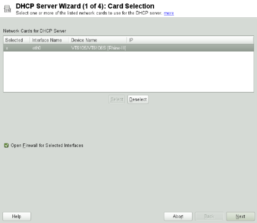
Card Selection
In the rst step, YaST looks for the network interfaces available on your system
and displays them in a list. From the list, select the interface to which the DHCP
server should listen and click Select. After this, select Open Firewall for Selected
Interfaces to open the rewall for this interface, and click Next. See Figure 12.1,
“DHCP Server: Card Selection” (page 243).
Figure 12.1 DHCP Server: Card Selection
Global Settings
Use the check box to determine whether your DHCP settings should be automati-
cally stored by an LDAP server. In the entry elds, provide the network specics
for all clients the DHCP server should manage. These specics are the domain
name, address of a time server, addresses of the primary and secondary name
server, addresses of a print and a WINS server (for a mixed network with both
Windows and Linux clients), gateway address, and lease time. See Figure 12.2,
“DHCP Server: Global Settings” (page 244).
DHCP 243

Figure 12.2 DHCP Server: Global Settings
Dynamic DHCP
In this step, congure how dynamic IP addresses should be assigned to clients. To
do so, specify an IP range from which the server can assign addresses to DHCP
clients. All these addresses must be covered by the same netmask. Also specify the
lease time during which a client may keep its IP address without needing to request
an extension of the lease. Optionally, specify the maximum lease time—the period
during which the server reserves an IP address for a particular client. See Fig-
ure 12.3, “DHCP Server: Dynamic DHCP” (page 245).
244 Reference

Figure 12.3 DHCP Server: Dynamic DHCP
Finishing the Conguration and Setting the Start Mode
After the third part of the conguration wizard, a last dialog is shown in which you
can dene how the DHCP server should be started. Here, specify whether to start
the DHCP server automatically when the system is booted or manually when
needed (for example, for testing purposes). Click Finish to complete the congura-
tion of the server. See Figure 12.4, “DHCP Server: Start-Up” (page 245).
Figure 12.4 DHCP Server: Start-Up
DHCP 245
12.2 DHCP Software Packages
Both the DHCP server and the DHCP clients are available for openSUSE. The DHCP
server available is dhcpd (published by the Internet Systems Consortium). On the client
side, choose between two different DHCP client programs: dhcp-client (also from
ISC) and the DHCP client daemon in the dhcpcd package.
openSUSE installs dhcpcd by default. The program is very easy to handle and is launched
automatically on each system boot to watch for a DHCP server. It does not need a
conguration le to do its job and works out of the box in most standard setups. For
more complex situations, use the ISC dhcp-client, which is controlled by means of the
conguration le /etc/dhclient.conf.
12.3 The DHCP Server dhcpd
The core of any DHCP system is the dynamic host conguration protocol daemon. This
server leases addresses and watches how they are used, according to the settings dened
in the conguration le /etc/dhcpd.conf. By changing the parameters and values
in this le, a system administrator can inuence the program's behavior in numerous
ways. Look at the basic sample /etc/dhcpd.conf le in Example 12.1, “The
Conguration File /etc/dhcpd.conf” (page 246).
Example 12.1 The Conguration File /etc/dhcpd.conf
default-lease-time 600; # 10 minutes
max-lease-time 7200; # 2 hours
option domain-name "example.com";
option domain-name-servers 192.168.1.116;
option broadcast-address 192.168.2.255;
option routers 192.168.2.1;
option subnet-mask 255.255.255.0;
subnet 192.168.2.0 netmask 255.255.255.0
{
range 192.168.2.10 192.168.2.20;
range 192.168.2.100 192.168.2.200;
}
246 Reference
This simple conguration le should be sufcient to get the DHCP server to assign IP
addresses in the network. Make sure that a semicolon is inserted at the end of each line,
because otherwise dhcpd is not started.
The sample le can be divided into three sections. The rst one denes how many
seconds an IP address is leased to a requesting client by default
(default-lease-time) before it should apply for renewal. This section also in-
cludes a statement of the maximum period for which a machine may keep an IP address
assigned by the DHCP server without applying for renewal (max-lease-time).
In the second part, some basic network parameters are dened on a global level:
•The line option domain-name denes the default domain of your network.
•With the entry option domain-name-servers, specify up to three values for
the DNS servers used to resolve IP addresses into hostnames and vice versa. Ideally,
congure a name server on your machine or somewhere else in your network before
setting up DHCP. That name server should also dene a hostname for each dynamic
address and vice versa. To learn how to congure your own name server, read
Chapter 11, The Domain Name System (page 215).
•The line option broadcast-address denes the broadcast address the re-
questing client should use.
•With option routers, set where the server should send data packets that cannot
be delivered to a host on the local network (according to the source and target host
address and the subnet mask provided). In most cases, especially in smaller networks,
this router is identical to the Internet gateway.
•With option subnet-mask, specify the netmask assigned to clients.
The last section of the le denes a network, including a subnet mask. To nish,
specify the address range that the DHCP daemon should use to assign IP addresses to
interested clients. In Example 12.1, “The Conguration File /etc/dhcpd.conf” (page 246),
clients may be given any address between 192.168.2.10 and 192.168.2.20 as
well as 192.168.2.100 and 192.168.2.200.
After editing these few lines, you should be able to activate the DHCP daemon with
the command rcdhcpd start. It will be ready for use immediately. Use the command
rcdhcpd check-syntax to perform a brief syntax check. If you encounter any
DHCP 247
unexpected problems with your conguration (the server aborts with an error or does
not return done on start), you should be able to nd out what has gone wrong by
looking for information either in the main system log /var/log/messages or on
console 10 (Ctrl +Alt +F10).
On a default openSUSE system, the DHCP daemon is started in a chroot environment
for security reasons. The conguration les must be copied to the chroot environment
so the daemon can nd them. Normally, there is no need to worry about this because
the command rcdhcpd start automatically copies the les.
12.3.1 Clients with Fixed IP Addresses
DHCP can also be used to assign a predened, static address to a specic client. Ad-
dresses assigned explicitly always take priority over dynamic addresses from the pool.
A static address never expires in the way a dynamic address would, for example, if
there were not enough addresses available and the server needed to redistribute them
among clients.
To identify a client congured with a static address, dhcpd uses the hardware address
(which is a globally unique, xed numerical code consisting of six octet pairs) for the
identication of all network devices (for example, 00:30:6E:08:EC:80). If the
respective lines, like the ones in Example 12.2, “Additions to the Conguration File”
(page 248), are added to the conguration le of Example 12.1, “The Conguration
File /etc/dhcpd.conf” (page 246), the DHCP daemon always assigns the same set of
data to the corresponding client.
Example 12.2 Additions to the Conguration File
host jupiter {
hardware ethernet 00:30:6E:08:EC:80;
fixed-address 192.168.2.100;
}
The name of the respective client (host hostname, here jupiter) is entered in
the rst line and the MAC address in the second line. On Linux hosts, nd the MAC
address with the command ip link show followed by the network device (for ex-
ample, eth0). The output should contain something like
link/ether 00:30:6E:08:EC:80
248 Reference
In the preceding example, a client with a network card having the MAC address
00:30:6E:08:EC:80 is assigned the IP address 192.168.2.100 and the hostname
jupiter automatically. The type of hardware to enter is ethernet in nearly all
cases, although token-ring, which is often found on IBM systems, is also supported.
12.3.2 The openSUSE Version
To improve security, the openSUSE version of the ISC's DHCP server comes with the
non-root/chroot patch by Ari Edelkind applied. This enables dhcpd to run with the user
ID nobody and run in a chroot environment (/var/lib/dhcp). To make this pos-
sible, the conguration le dhcpd.conf must be located in /var/lib/dhcp/
etc. The init script automatically copies the le to this directory when starting.
Control the server's behavior regarding this feature by means of entries in the le /etc/
sysconfig/dhcpd. To run dhcpd without the chroot environment, set the variable
DHCPD_RUN_CHROOTED in /etc/sysconfig/dhcpd to “no”.
To enable dhcpd to resolve hostnames even from within the chroot environment, some
other conguration les must be copied as well:
•/etc/localtime
•/etc/host.conf
•/etc/hosts
•/etc/resolv.conf
These les are copied to /var/lib/dhcp/etc/ when starting the init script. Take
these copies into account for any changes that they require if they are dynamically
modied by scripts like /etc/ppp/ip-up. However, there should be no need to
worry about this if the conguration le only species IP addresses (instead of host-
names).
If your conguration includes additional les that should be copied into the chroot en-
vironment, set these under the variable DHCPD_CONF_INCLUDE_FILES in the le
/etc/sysconfig/dhcpd. To ensure that the DHCP logging facility keeps working
DHCP 249
even after a restart of the syslog-ng daemon, there is an additional entry
SYSLOGD_ADDITIONAL_SOCKET_DHCP in the le /etc/sysconfig/syslog.
12.4 For More Information
More information about DHCP is available at the Web site of the Internet Systems
Consortium (http://www.isc.org/products/DHCP/). Information is also
available in the dhcpd,dhcpd.conf,dhcpd.leases, and dhcp-options man
pages.
250 Reference
13
Time Synchronization with
NTP
The NTP (network time protocol) mechanism is a protocol for synchronizing the system
time over the network. First, a machine can obtain the time from a server that is a reliable
time source. Second, a machine can itself act as a time source for other computers in
the network. The goal is twofold—maintaining the absolute time and synchronizing
the system time of all machines within a network.
Maintaining an exact system time is important in many situations. The built-in hardware
(BIOS) clock does often not meet the requirements of applications such as databases
or clusters. Manual correction of the system time would lead to severe problems because,
for example, a backward leap can cause malfunction of critical applications. Within a
network, it is usually necessary to synchronize the system time of all machines, but
manual time adjustment is a bad approach. NTP provides a mechanism to solve these
problems. The NTP service continuously adjusts the system time with the help of reliable
time servers in the network. It further enables the management of local reference clocks,
such as radio-controlled clocks.
13.1 Conguring an NTP Client with
YaST
The NTP daemon (ntpd) coming with the ntp package is preset to use the local
computer clock as a time reference. Using the (BIOS) clock, however, only serves as
a fallback for cases where no time source of better precision is available. YaST facilitates
the conguration of an NTP client.
Time Synchronization with NTP 251

13.1.1 Basic Conguration
The YaST NTP client conguration (Network Services >NTP Conguration) consists
of tabs. Set the start mode of ntpd and the server to query on the General Settings tab.
Figure 13.1 Advanced NTP Conguration: General Settings
Only Manually
Select Only Manually, if you want to congure everything on your own.
Synchronize without Daemon
On laptops and other machines that suspend automatically, select Synchronize
without Daemon. Using this mode, YaST does not start ntpd on the local machine
for synchronizing. Instead YaST creates a crontab entry (/etc/cron.d/novell
.ntp-synchronize) that checks the time with the time server as specied in
the Interval of the Synchronization in Minutes eld. For more information about
cron, see Section 7.1.2, “The cron Package” (page 122).
252 Reference

Now and On Boot
Select Now and On Boot to start ntpd automatically when the system is booted.
Either of 0.opensuse.pool.ntp.org,1.opensuse.pool.ntp.org,
2.opensuse.pool.ntp.org, or 3.opensuse.pool.ntp.org is pre-
selected.
13.1.2 Changing Basic Conguration
The servers and other time sources for the client to query are listed in the lower part of
the General Settings tab. Modify this list as needed with Add,Edit, and Delete.Display
Log provides the possibility to view the log les of your client.
Click Add to add a new source of time information. In the following dialog, select the
type of source with which the time synchronization should be made. The following
options are available:
Figure 13.2 YaST: NTP Server
Time Synchronization with NTP 253
Server
In the pull-down Select list (see Figure 13.2, “YaST: NTP Server” (page 253), de-
termine whether to set up time synchronization using a time server from your local
network (Local NTP Server) or an Internet-based time server that takes care of
your time zone (Public NTP Server). For a local time server, click Lookup to start
an SLP query for available time servers in your network. Select the most suitable
time server from the list of search results and exit the dialog with OK. For a public
time server, select your country (time zone) and a suitable server from the list under
Public NTP Server then exit the dialog with OK. In the main dialog, test the avail-
ability of the selected server with Test.
Another dialog enables you to select an NTP server. Activate Use for Initial Syn-
chronization to trigger the synchronization of the time information between the
server and the client when the system is booted. Options allows you to specify ad-
ditional options for ntpd.
Using Access Control Options, you can restrict the actions that the remote computer
can perform with the daemon running on your computer. This eld is enabled only
after checking Restrict NTP Service to Congured Servers Only on the Security
Settings tab (see Figure 13.3, “Advanced NTP Conguration: Security Settings”
(page 255)). The options correspond to the restrict clauses in /etc/ntp
.conf. For example, nomodify notrap noquery disallows the server to
modify NTP settings of your computer and to use the trap facility (a remote event
logging feature) of your NTP daemon. Using these restrictions is recommended
for servers out of your control (for example, on the Internet).
Refer to /usr/share/doc/packages/ntp-doc (part of the ntp-doc
package) for detailed information.
Peer
A peer is a machine to which a symmetric relationship is established: it acts both
as a time server and as a client. To use a peer in the same network instead of a
server, enter the address of the system. The rest of the dialog is identical to the
Server dialog.
Radio Clock
To use a radio clock in your system for the time synchronization, enter the clock
type, unit number, device name, and other options in this dialog. Click Driver
Calibration to ne-tune the driver. Detailed information about the operation of a
254 Reference
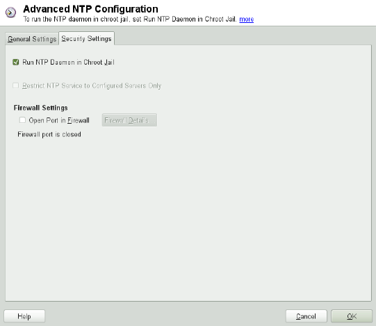
local radio clock is available in /usr/share/doc/packages/ntp-doc/
refclock.html.
Outgoing Broadcast
Time information and queries can also be transmitted by broadcast in the network.
In this dialog, enter the address to which such broadcasts should be sent. Do not
activate broadcasting unless you have a reliable time source like a radio controlled
clock.
Incoming Broadcast
If you want your client to receive its information via broadcast, enter the address
from which the respective packets should be accepted in this elds.
Figure 13.3 Advanced NTP Conguration: Security Settings
In the Security Settings tab (see Figure 13.3, “Advanced NTP Conguration: Security
Settings” (page 255)), determine whether ntpd should be started in a chroot jail. By
default, Run NTP Daemon in Chroot Jail is activated. This increases the security in the
event of an attack over ntpd, as it prevents the attacker from compromising the entire
system.
Time Synchronization with NTP 255
Restrict NTP Service to Congured Servers Only increases the security of your system
by disallowing remote computers to view and modify NTP settings of your computer
and to use the trap facility for remote event logging. Once enabled, these restrictions
apply to all remote computers, unless you override the access control options for indi-
vidual computers in the list of time sources in the General Settings tab. For all other
remote computers, only querying for local time is allowed.
Enable Open Port in Firewall if SuSErewall2 is active (which it is by default). If you
leave the port closed, it is not possible to establish a connection to the time server.
13.2 Manually Conguring ntp in the
Network
The easiest way to use a time server in the network is to set server parameters. For ex-
ample, if a time server called ntp.example.com is reachable from the network, add
its name to the le /etc/ntp.conf by adding the following line:
server ntp.example.com
To add more time servers, insert additional lines with the keyword server. After
initializing ntpd with the command rcntp start, it takes about one hour until the
time is stabilized and the drift le for correcting the local computer clock is created.
With the drift le, the systematic error of the hardware clock can be computed as soon
as the computer is powered on. The correction is used immediately, resulting in a
higher stability of the system time.
There are two possible ways to use the NTP mechanism as a client: First, the client can
query the time from a known server in regular intervals. With many clients, this approach
can cause a high load on the server. Second, the client can wait for NTP broadcasts sent
out by broadcast time servers in the network. This approach has the disadvantage that
the quality of the server is unknown and a server sending out wrong information can
cause severe problems.
If the time is obtained via broadcast, you do not need the server name. In this case, enter
the line broadcastclient in the conguration le /etc/ntp.conf. To use one
or more known time servers exclusively, enter their names in the line starting with
servers.
256 Reference
13.3 Dynamic Time Synchronization
at Runtime
If the system boots without network connection, ntpd starts up, but it cannot resolve
DNS names of the time servers set in the conguration le. This can happen if you use
Network Manager with an encrypted WLAN.
If you want ntpd to resolve DNS names at runtime, you must set the dynamic option.
Then, when the network is establish some time after booting, ntpd looks up the names
again and can reach the time servers to get the time.
Manually edit /etc/ntp.conf and add dynamic to one or more server entries:
server ntp.example.com dynamic
Or use YaST and proceed as follows:
1In YaST click Network Services >NTP Conguration.
2Select the server you want to congure. Then click Edit.
3Activate the Options eld and add dynamic. Separate it with a space, if there are
already other options entered.
4Click Ok to close the edit dialog. Repeat the previous step to change all servers as
wanted.
5Finally click Ok to save the settings.
13.4 Setting Up a Local Reference
Clock
The software package ntp contains drivers for connecting local reference clocks. A list
of supported clocks is available in the ntp-doc package in the le /usr/share/
doc/packages/ntp-doc/refclock.html. Every driver is associated with a
number. In ntp, the actual conguration takes place by means of pseudo IP addresses.
Time Synchronization with NTP 257
The clocks are entered in the le /etc/ntp.conf as though they existed in the net-
work. For this purpose, they are assigned special IP addresses in the form
127.127.t.u. Here, tstands for the type of the clock and determines which driver
is used and ufor the unit, which determines the interface used.
Normally, the individual drivers have special parameters that describe conguration
details. The le /usr/share/doc/packages/ntp-doc/drivers/driverNN
.html (where NN is the number of the driver) provides information about the particular
type of clock. For example, the “type 8” clock (radio clock over serial interface) requires
an additional mode that species the clock more precisely. The Conrad DCF77 receiver
module, for example, has mode 5. To use this clock as a preferred reference, specify
the keyword prefer. The complete server line for a Conrad DCF77 receiver
module would be:
server 127.127.8.0 mode 5 prefer
Other clocks follow the same pattern. Following the installation of the ntp-doc
package, the documentation for ntp is available in the directory /usr/share/doc/
packages/ntp-doc. The le /usr/share/doc/packages/ntp-doc/
refclock.html provides links to the driver pages describing the driver parameters.
258 Reference

14
Sharing File Systems with NFS
Distributing and sharing le systems over a network is a common task in corporate
environments. The well-proven network le system (NFS) works together with NIS,
the yellow pages protocol. For a more secure protocol that works together with LDAP
and may also use Kerberos, check NFSv4.
NFS with NIS makes a network transparent to the user. With NFS, it is possible to
distribute arbitrary le systems over the network. With an appropriate setup, users always
nd themselves in the same environment regardless of the terminal they currently use.
IMPORTANT: Need for DNS
In principle, all exports can be made using IP addresses only. To avoid time-
outs, you need a working DNS system. DNS is necessary at least for logging
purposes, because the mountd daemon does reverse lookups.
14.1 Terminology
The following are terms used in the YaST module.
Exports
A directory exported by an NFS server, which clients can integrate it into their
system.
Sharing File Systems with NFS 259
NFS Client
The NFS client is a system that uses NFS services from an NFS server over the
Network File System protocol. The TCP/IP protocol is already integrated into the
Linux kernel; there is no need to install any additional software.
NFS Server
The NFS server provides NFS services to clients. A running server depends on the
following daemons: nfsd (worker), idmapd (user and group name mappings to
IDs and vice versa), statd (le locking), and mountd (mount requests).
14.2 Installing NFS Server
The NFS server software is not part of the default installation. To install the NFS
server software, start YaST and select Software >Software Management. Now choose
Filter >Patterns and select File Server or use the Search option and search for NFS
Server. Conrm the installation of the packages to nish the installation process.
Like NIS, NFS is a client/server system. However, a machine can be both—it can supply
le systems over the network (export) and mount le systems from other hosts (import).
14.3 Conguring NFS Server
Conguring an NFS server can be done either through YaST or manually. For authen-
tication, NFS can also be combined with Kerberos.
14.3.1 Exporting File Systems with YaST
With YaST, turn a host in your network into an NFS server—a server that exports di-
rectories and les to all hosts granted access to it. The server can also provide applica-
tions to all members of a group without installing the applications locally on each and
every host. To set up such a server, proceed as follows:
1Start YaST and select Network Services >NFS Server; see Figure 14.1, “NFS Server
Conguration Tool” (page 261).
260 Reference
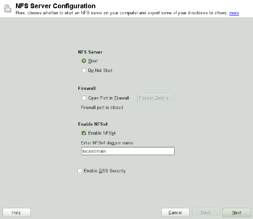
Figure 14.1 NFS Server Conguration Tool
2Activate the Start radio button and enter the NFSv4 Domain Name.
3Click Enable GSS Security if you need secure access to the server. A prerequisite
for this is to have Kerberos installed on your domain and to have both the server and
the clients kerberized. Click Next.
4Enter the directories to export in the upper text eld. Below, enter the hosts that
should have access to them. This dialog is shown in Figure 14.2, “Conguring an
NFS Server with YaST” (page 262).
Sharing File Systems with NFS 261
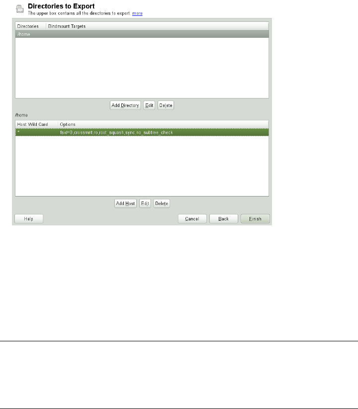
Figure 14.2 Conguring an NFS Server with YaST
The gure shows the scenario where NFSv4 is enabled in the previous dialog.
Bindmount Targets is shown in the right pane. For more details, click Help.
In the lower half of the dialog, there are four options that can be set for each host:
single host,netgroups,wildcards, and IP networks. For a more
thorough explanation of these options, refer to the exports man page.
5Click Finish to complete the conguration.
IMPORTANT: Automatic Firewall Conguration
If a rewall is active on your system (SuSErewall2), YaST adapts its conguration
for the NFS server by enabling the nfs service when Open Ports in Firewall is
selected.
262 Reference
14.3.1.1 Exporting for NFSv4 Clients
Activate Enable NFSv4 to support NFSv4 clients. Clients with NFSv3 can still access
the server's exported directories if they are exported appropriately. This is explained in
detail in Section 14.3.1.3, “Coexisting v3 and v4 Exports” (page 266).
After activating NFSv4, enter an appropriate domain name. Make sure the name is the
same as the one in the /etc/idmapd.conf le of any NFSv4 client that accesses
this particular server. This parameter is for the idmapd service that is required for NFSv4
support (on both server and client). Leave it as localdomain (the default) if you do
not have special requirements. For more information, see the links in Section 14.5, “For
More Information” (page 273).
Click Next. The dialog that follows has two sections. The upper half consists of two
columns named Directories and Bind Mount Targets.Directories is a directly editable
column that lists the directories to export.
For a xed set of clients, there are two types of directories that can be exported—direc-
tories that act as pseudo root le systems and those that are bound to some subdirectory
of the pseudo le system. This pseudo le system acts as a base point under which all
le systems exported for the same client set take their place. For a client or set of clients,
only one directory on the server can be congured as pseudo root for export. For this
client, export multiple directories by binding them to some existing subdirectory in the
pseudo root.
Sharing File Systems with NFS 263

Figure 14.3 Exporting Directories with NFSv4
In the lower half of the dialog, enter the client (wild card) and export options for a
particular directory. After adding a directory in the upper half, another dialog for entering
the client information and options pops up automatically. After that, to add a new client
or a set of clients, click Add Host.
In the small dialog that opens, enter the host wild card. There are four possible types
of host wild cards that can be set for each host: a single host (name or IP address), net-
groups, wild cards (such as *indicating all machines can access the server), and IP
networks. Then, in Options, include fsid=0 in the comma-separated list of options
to congure the directory as pseudo root. If this directory needs to be bound to another
directory under an already congured pseudo root, make sure that a target bind path is
given in the option list with bind=/target/path.
For example, suppose that the directory /exports is chosen as the pseudo root direc-
tory for all the clients that can access the server. Then add this in the upper half and
make sure that the options entered for this directory include fsid=0. If there is another
directory, /data, that also needs to be NFSv4 exported, add this directory to the upper
half. While entering options for this, make sure that bind=/exports/data is in
264 Reference
the list and that /exports/data is an already existing subdirectory of /exports.
Any change in the option bind=/target/path, whether addition, deletion, or
change in value, is reected in Bindmount Targets. This column is not a directly editable
column, but instead summarizes directories and their nature. After all information is
provided, click Finish to complete the conguration. The service will become available
immediately.
14.3.1.2 NFSv3 and NFSv2 Exports
Make sure that Enable NFSv4 is not checked in the initial dialog before clicking Next.
The next dialog has two parts. In the upper text eld, enter the directories to export.
Below, enter the hosts that should have access to them. There are four types of host
wild cards that can be set for each host: a single host (name or IP address), netgroups,
wild cards (such as *indicating all machines can access the server), and IP networks.
This dialog is shown in Figure 14.4, “Exporting Directories with NFSv2 and v3”
(page 266). Find a more thorough explanation of these options in man exports. Click
Finish to complete the conguration.
Sharing File Systems with NFS 265
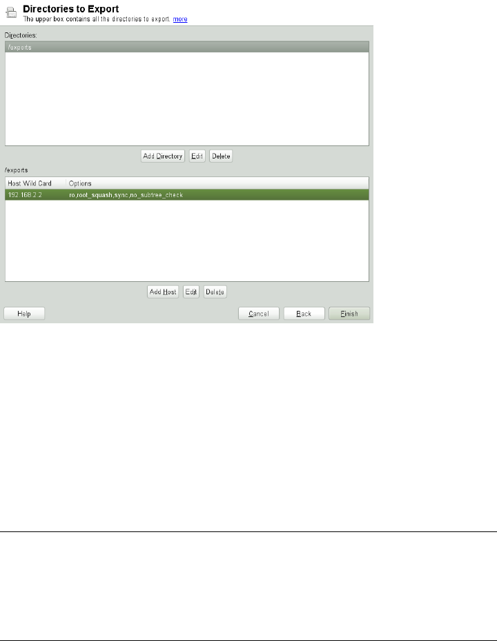
Figure 14.4 Exporting Directories with NFSv2 and v3
14.3.1.3 Coexisting v3 and v4 Exports
NFSv3 and NFSv4 exports can coexist on a server. After enabling the support for NFSv4
in the initial conguration dialog, those exports for which fsid=0 and
bind=/target/path are not included in the option list are considered v3 exports.
Consider the example in Figure 14.2, “Conguring an NFS Server with YaST”
(page 262). If you add another directory, such as /data2, using Add Directory then in
the corresponding options list do not mention either fsid=0 or
bind=/target/path, this export acts as a v3 export.
IMPORTANT
Automatic Firewall Conguration
If SuSErewall2 is active on your system, YaST adapts its conguration for the
NFS server by enabling the nfs service when Open Ports in Firewall is selected.
266 Reference
14.3.2 Exporting File Systems Manually
The conguration les for the NFS export service are /etc/exports and /etc/
sysconfig/nfs. In addition to these les, /etc/idmapd.conf is needed for
the NFSv4 server conguration. To start or restart the services, run the command
rcnfsserver restart. This also starts the rpc.idmapd if NFSv4 is congured
in /etc/sysconfig/nfs. The NFS server depends on a running RPC portmapper.
Therefore, also start or restart the portmapper service with rcrpcbind restart.
14.3.2.1 Exporting File Systems with NFSv4
NFSv4 is the latest version of NFS protocol available on openSUSE. Conguring direc-
tories for export with NFSv4 differs slightly from previous NFS versions.
/etc/exports
The /etc/exports le contains a list of entries. Each entry indicates a directory
that is shared and how it is shared. A typical entry in /etc/exports consists of:
/shared/directory host(option_list)
For example:
/export 192.168.1.2(rw,fsid=0,sync,crossmnt)
/export/data 192.168.1.2(rw,bind=/data,sync)
Here the IP address 192.168.1.2 is used to identify the allowed client. You can also
use the name of the host, a wild card indicating a set of hosts (*.abc.com,*, etc.),
or netgroups (@my-hosts).
The directory which species fsid=0 is special. It is the root of the lesystem that is
exported, sometimes referred to as the pseudo root lesystem. This directory must also
have the crossmnt for correct operation with NFSv4. All other directories exported
via NFSv4 must be mounted below this point. If you want to export a directory that is
not within the exported root, it needs to be bound into the exported tree. This can be
done using the bind= syntax.
In the example above, /data is not within /export, so we export /export/data,
and specify that the /data directory should be bound to that name. The directory
/export/data must exist and should normally be empty.
Sharing File Systems with NFS 267
When clients mount from this server, they just mount servername:/ rather than
servername:/export. It is not necessary to mount servername:/data, because
it will automatically appear beneath wherever servername:/ was mounted.
/etc/syscong/nfs
The /etc/sysconfig/nfs le contains a few parameters that determine NFSv4
server daemon behavior. It is important to set the parameter NFS4_SUPPORT to yes.
NFS4_SUPPORT determines whether the NFS server supports NFSv4 exports and
clients.
/etc/idmapd.conf
Every user on a Linux machine has a name and ID. idmapd does the name-to-ID mapping
for NFSv4 requests to the server and replies to the client. It must be running on both
server and client for NFSv4, because NFSv4 uses only names for its communication.
Make sure that there is a uniform way in which usernames and IDs (uid) are assigned
to users across machines that might probably be sharing le systems using NFS. This
can be achieved by using NIS, LDAP, or any uniform domain authentication mechanism
in your domain.
The parameter Domain must be set the same for both, client and server in the /etc/
idmapd.conf le. If you are not sure, leave the domain as localdomain in the
server and client les. A sample conguration le looks like the following:
[General]
Verbosity = 0
Pipefs-Directory = /var/lib/nfs/rpc_pipefs
Domain = localdomain
[Mapping]
Nobody-User = nobody
Nobody-Group = nobody
For further reference, read the man page of idmapd and idmapd.conf;man
idmapd,man idmapd.conf.
268 Reference
Starting and Stopping Services
After changing /etc/exports or /etc/sysconfig/nfs, start or restart the
NFS server service with rcnfsserver restart. After changing /etc/idmapd
.conf, reload the conguration le with the command killall -HUP
rpc.idmapd.
If the NFS service needs to start at boot time, run the command chkconfig
nfsserver on.
14.3.2.2 Exporting File Systems with NFSv2 and
NFSv3
This section is specic to NFSv3 and NFSv2 exports. Refer to Section 14.3.1.1, “Ex-
porting for NFSv4 Clients” (page 263) for exporting with NFSv4.
Exporting le systems with NFS involves two conguration les: /etc/exports
and /etc/sysconfig/nfs. A typical /etc/exports le entry is in the format:
/shared/directory host(list_of_options)
For example:
/export 192.168.1.2(rw,sync)
Here, the directory /export is shared with the host 192.168.1.2 with the option
list rw,sync. This IP address can be replaced with a client name or set of clients using
a wild card (such as *.abc.com) or even netgroups.
For a detailed explanation of all options and their meaning, refer to the man page of
exports (man exports).
After changing /etc/exports or /etc/sysconfig/nfs, start or restart the
NFS server using the command rcnfsserver restart.
14.3.3 NFS with Kerberos
To use Kerberos authentication for NFS, GSS security must be enabled. Select Enable
GSS Security in the initial YaST NFS Server dialog. You must have a working Kerberos
Sharing File Systems with NFS 269
server to use this feature. YaST does not set up the server but just uses the provided
functionality. If you want to use Kerberos authentication in addition to the YaST con-
guration, complete at least the following steps before running the NFS conguration:
1Make sure that both the server and the client are in the same Kerberos domain. They
must access the same KDC (Key Distribution Center) server and share their krb5
.keytab le (the default location on any machine is /etc/krb5.keytab). For
more information about Kerberos, see Chapter 6, Network Authentication with Ker-
beros (↑Security Guide).
2Start the gssd service on the client with rcgssd start.
3Start the svcgssd service on the server with rcsvcgssd start.
For more information about conguring kerberized NFS, refer to the links in Sec-
tion 14.5, “For More Information” (page 273).
14.4 Conguring Clients
To congure your host as an NFS client, you do not need to install additional software.
All needed packages are installed by default.
14.4.1 Importing File Systems with YaST
Authorized users can mount NFS directories from an NFS server into the local le tree
using the YaST NFS client module. Click on Add and enter the hostname of the NFS
server, the directory to import, and the mount point at which to mount this directory
locally. The changes will take effect after clicking Finish in the rst dialog.
In the NFS Settings tab, enable Open Port in Firewall to allow access to the service
from remote computers. The rewall status is displayed next to the check box. When
using NFSv4, make sure that the checkbox Enable NFSv4 is selected and that the NFSv4
Domain Name contains the same value as used by the NFSv4 server. The default domain
is localdomain.
Click OK to save your changes. See Figure 14.5, “NFS Client Conguration with YaST”
(page 271).
270 Reference
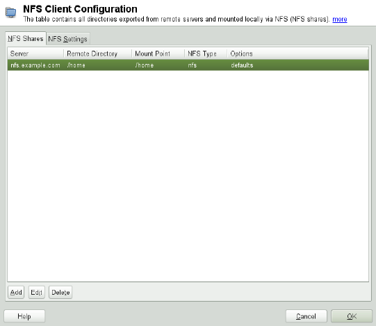
The conguration is written to /etc/fstab and the specied le systems are
mounted. When you start the YaST conguration client at a later time, it also reads the
existing conguration from this le.
Figure 14.5 NFS Client Conguration with YaST
14.4.2 Importing File Systems Manually
The prerequisite for importing le systems manually from an NFS server is a running
RPC port mapper. Start it by entering rcrpcbind start as root. Then remote
le systems can be mounted in the le system like local partitions using mount:
mount host:remote-pathlocal-path
To import user directories from the nfs.example.com machine, for example, use:
mount nfs.example.com:/home /home
Sharing File Systems with NFS 271
14.4.2.1 Using the Automount Service
The autofs daemon can be used to mount remote le systems automatically. Add the
following entry in the your /etc/auto.master le:
/nfsmounts /etc/auto.nfs
Now the /nfsmounts directory acts as the root for all the NFS mounts on the client
if the auto.nfs le is lled appropriately. The name auto.nfs is chosen for the
sake of convenience—you can choose any name. In auto.nfs add entries for all the
NFS mounts as follows:
localdata -fstype=nfs server1:/data
nfs4mount -fstype=nfs4 server2:/
Activate the settings with rcautofs start as root. In this example,
/nfsmounts/localdata, the /data directory of server1, is mounted with
NFS and /nfsmounts/nfs4mount from server2 is mounted with NFSv4.
If the /etc/auto.master le is edited while the service autofs is running, the au-
tomounter must be restarted for the changes to take effect with rcautofs restart.
14.4.2.2 Manually Editing /etc/fstab
A typical NFSv3 mount entry in /etc/fstab looks like this:
nfs.example.com:/data /local/path nfs rw,noauto 0 0
NFSv4 mounts may also be added to the /etc/fstab le. For these mounts, use
nfs4 instead of nfs in the third column and make sure that the remote le system is
given as /after the nfs.example.com: in the rst column. A sample line for an
NFSv4 mount in /etc/fstab looks like this:
nfs.example.com:/ /local/pathv4 nfs4 rw,noauto 0 0
The noauto option prevents the le system from being mounted automatically at start
up. If you want to mount the respective le system manually, it is possible to shorten
the mount command specifying the mount point only:
mount /local/path
272 Reference
Note, that if you do not enter the noauto option, the initialization scripts of the system
will handle the mount of those le systems at start up.
14.5 For More Information
In addition to the man pages of exports,nfs, and mount, information about con-
guring an NFS server and client is available in /usr/share/doc/packages/
nfsidmap/README. For further documentation online refer to the following Web
sites:
•Find the detailed technical documentation online at SourceForge [http://nfs
.sourceforge.net/].
• For instructions for setting up kerberized NFS, refer to NFS Version 4 Open Source
Reference Implementation [http://www.citi.umich.edu/projects/
nfsv4/linux/krb5-setup.html].
•If you have questions on NFSv4, refer to the Linux NFSv4 FAQ [http://www
.citi.umich.edu/projects/nfsv4/linux/faq/].
Sharing File Systems with NFS 273
15
Samba
Using Samba, a Unix machine can be congured as a le and print server for Mac OS
X, Windows, and OS/2 machines. Samba has developed into a fully-edged and rather
complex product. Congure Samba with YaST, SWAT (a Web interface), or by editing
the conguration le manually.
15.1 Terminology
The following are some terms used in Samba documentation and in the YaST module.
SMB protocol
Samba uses the SMB (server message block) protocol that is based on the NetBIOS
services. Microsoft released the protocol so other software manufacturers could
establish connections to a Microsoft domain network. With Samba, the SMB pro-
tocol works on top of the TCP/IP protocol, so the TCP/IP protocol must be installed
on all clients.
CIFS protocol
CIFS (common Internet le system) protocol is another protocol supported by
Samba. CIFS denes a standard remote le system access protocol for use over
the network, enabling groups of users to work together and share documents across
the network.
NetBIOS
NetBIOS is a software interface (API) designed for communication between ma-
chines providing a name service. It enables machines connected to the network to
Samba 275
reserve names for themselves. After reservation, these machines can be addressed
by name. There is no central process that checks names. Any machine on the net-
work can reserve as many names as it wants as long as the names are not already
in use. The NetBIOS interface can be implemented for different network architec-
tures. An implementation that works relatively closely with network hardware is
called NetBEUI, but this is often referred to as NetBIOS. Network protocols imple-
mented with NetBIOS are IPX from Novell (NetBIOS via TCP/IP) and TCP/IP.
The NetBIOS names sent via TCP/IP have nothing in common with the names
used in /etc/hosts or those dened by DNS. NetBIOS uses its own, completely
independent naming convention. However, it is recommended to use names that
correspond to DNS hostnames to make administration easier or use DNS natively.
This is the default used by Samba.
Samba server
Samba server provides SMB/CIFS services and NetBIOS over IP naming services
to clients. For Linux, there are three daemons for Samba server: smbd for SMB/CIFS
services, nmbd for naming services, and winbind for authentication.
Samba client
The Samba client is a system that uses Samba services from a Samba server over
the SMB protocol. All common operating systems, such as Mac OS X, Windows,
and OS/2, support the SMB protocol. The TCP/IP protocol must be installed on all
computers. Samba provides a client for the different UNIX avors. For Linux,
there is a kernel module for SMB that allows the integration of SMB resources on
the Linux system level. You do not need to run any daemon for the Samba client.
Shares
SMB servers provide resources to the clients by means of shares. Shares are printers
and directories with their subdirectories on the server. It is exported by means of
a name and can be accessed by its name. The share name can be set to any name—it
does not have to be the name of the export directory. A printer is also assigned a
name. Clients can access the printer by its name.
DC
A domain controller (DC) is a server that handles accounts in domain. For data
replication, additional domain controllers are available in one domain.
276 Reference
15.2 Installing a Samba Server
To install a Samba server, start YaST and select Software >Software Management.
Choose Filter >Patterns and select File Server. Conrm the installation of the required
packages to nish the installation process.
15.3 Starting and Stopping Samba
You can start or stop the Samba server automatically (during boot) or manually. Starting
and stopping policy is a part of the YaST Samba server conguration described in
Section 15.4.1, “Conguring a Samba Server with YaST” (page 277).
To stop or start running Samba services with YaST, use System >System Services
(Runlevel) and check winbind, smb, and nmb. From a command line, stop services re-
quired for Samba with rcsmb stop && rcnmb stop and start them with rcnmb
start && rcsmb start; rcsmb cares about winbind if needed.
15.4 Conguring a Samba Server
A Samba server in openSUSE® can be congured in two different ways: with YaST
or manually. Manual conguration offers a higher level of detail, but lacks the conve-
nience of the YaST GUI.
15.4.1 Conguring a Samba Server with
YaST
To congure a Samba server, start YaST and select Network Services >Samba Server.
15.4.1.1 Initial Samba Conguration
When starting the module for the rst time, the Samba Installation dialog starts,
prompting you to make just a few basic decisions concerning administration of the
server. At the end of the conguration it prompts for the Samba administrator password
(Samba Root Password. For later starts, the Samba Server Conguration dialog appears.
Samba 277
The Samba Installation dialog consists of two steps and optional detailed settings:
Workgroup or Domain Name
Select an existing name from Workgroup or Domain Name or enter a new one and
click Next.
Samba Server Type
In the next step, specify whether your server should act as a primary domain con-
troller (PDC), backup domain controller (BDC), or not to act as a domain controller
at all. Continue with Next.
Start-Up
Select whether you want to start Samba During Boot or Manually and click OK.
Then in the nal pop-up box, set the Samba root Password.
You can change all settings later in the Samba Conguration dialog with the Start-Up,
Shares,Identity,Trusted Domains, and LDAP Settings tabs.
15.4.1.2 Advanced Samba Conguration
During the rst start of the Samba server module the Samba Conguration dialog appears
directly after the two initial steps described in Section 15.4.1.1, “Initial Samba Con-
guration” (page 277). Use it to adjust your Samba server conguration.
After editing your conguration, click OK to save your settings.
Starting the Server
In the Start Up tab, congure the start of the Samba server. To start the service every
time your system boots, select During Boot. To activate manual start, choose Manually.
More information about starting a Samba server is provided in Section 15.3, “Starting
and Stopping Samba” (page 277).
In this tab, you can also open ports in your rewall. To do so, select Open Port in
Firewall. If you have multiple network interfaces, select the network interface for
Samba services by clicking Firewall Details, selecting the interfaces, and clicking OK.
278 Reference
Shares
In the Shares tab, determine the Samba shares to activate. There are some predened
shares, like homes and printers. Use Toggle Status to switch between Active and Inactive.
Click Add to add new shares and Delete to delete the selected share.
Allow Users to Share Their Directories enables members of the group in Permitted
Group to share directories they own with other users. For example, users for a local
scope or DOMAIN\Users for a domain scope. The user also must make sure that the
le system permissions allow access. With Maximum Number of Shares, limit the total
amount of shares that may be created. To permit access to user shares without authen-
tication, enable Allow Guest Access.
Identity
In the Identity tab, you can determine the domain with which the host is associated
(Base Settings) and whether to use an alternative hostname in the network (NetBIOS
Hostname). It is also possible to use Microsoft Windows Internet Name Service (WINS)
for name resolution. In this case, activate Use WINS for Hostname Resolution and decide
whether to Retrieve WINS server via DHCP. To set expert global settings or set a user
authentication source, click Advanced Settings.
Trusted Domains
To enable users from other domains to access your domain, make the appropriate settings
in the Trusted Domains tab. To add a new domain, click Add. To remove the selected
domain, click Delete.
LDAP Settings
In the tab LDAP Settings, you can determine the LDAP server to use for authentication.
To test the connection to your LDAP server, click Test Connection. To set expert LDAP
settings or use default values, click Advanced Settings.
For more information about LDAP conguration, see Chapter 4, LDAP—A Directory
Service (↑Security Guide).
Samba 279

15.4.2 Web Administration with SWAT
An alternative tool for Samba server administration is SWAT (Samba Web Administra-
tion Tool). It provides a simple Web interface with which to congure the Samba
server. To use SWAT, open http://localhost:901 in a Web browser and log
in as user root. If you do not have a special Samba root account, use the system root
account.
NOTE: Activating SWAT
After Samba server installation, SWAT is not activated. To activate it, open
Network Services >Network Services (xinetd) in YaST, enable the network services
conguration, select swat from the table, and click Toggle Status (On or Off).
15.4.3 Conguring the Server Manually
If you intend to use Samba as a server, install samba. The main conguration le of
Samba is /etc/samba/smb.conf. This le can be divided into two logical parts.
The [global] section contains the central and global settings. The [share] sections
contain the individual le and printer shares. By means of this approach, details regarding
the shares can be set differently or globally in the [global] section, which enhances
the structural transparency of the conguration le.
15.4.3.1 The global Section
The following parameters of the [global] section need some adjustment to match
the requirements of your network setup so other machines can access your Samba
server via SMB in a Windows environment.
workgroup = TUX-NET
This line assigns the Samba server to a workgroup. Replace TUX-NET with an
appropriate workgroup of your networking environment. Your Samba server appears
under its DNS name unless this name has been assigned to some other machine in
the network. If the DNS name is not available, set the server name using
netbiosname=MYNAME. For more details about this parameter, see the
smb.conf man page.
280 Reference
os level = 20
This parameter triggers whether your Samba server tries to become LMB (local
master browser) for its workgroup. With the Samba 3 release series, it is seldom
necessary to override the default setting (20). Choose a very low value such as 2
to spare the existing Windows network from any disturbances caused by a miscon-
gured Samba server. More information about this important topic can be found
in the Network Browsing chapter of the Samba 3 Howto; for more information on
the Samba 3 Howto, see Section 15.7, “For More Information” (page 286).
If no other SMB server is present in your network (such as a Windows 2000 server)
and you want the Samba server to keep a list of all systems present in the local
environment, set the os level to a higher value (for example, 65). Your Samba
server is then chosen as LMB for your local network.
When changing this setting, consider carefully how this could affect an existing
Windows network environment. First test the changes in an isolated network or at
a noncritical time of day.
wins support and wins server
To integrate your Samba server into an existing Windows network with an active
WINS server, enable the wins server option and set its value to the IP address
of that WINS server.
If your Windows machines are connected to separate subnets and need to still be
aware of each other, you need to set up a WINS server. To turn a Samba server
into such a WINS server, set the option wins support = Yes. Make sure that
only one Samba server of the network has this setting enabled. The options wins
server and wins support must never be enabled at the same time in your
smb.conf le.
15.4.3.2 Shares
The following examples illustrate how a CD-ROM drive and the user directories
(homes) are made available to the SMB clients.
[cdrom]
To avoid having the CD-ROM drive accidentally made available, these lines are
deactivated with comment marks (semicolons in this case). Remove the semicolons
in the rst column to share the CD-ROM drive with Samba.
Samba 281
Example 15.1 A CD-ROM Share (deactivated)
;[cdrom]
; comment = Linux CD-ROM
; path = /media/cdrom
; locking = No
[cdrom] and comment
The [cdrom] section entry is the name of the share that can be seen by all
SMB clients on the network. An additional comment can be added to further
describe the share.
path = /media/cdrom
path exports the directory /media/cdrom.
By means of a very restrictive default conguration, this kind of share is only made
available to the users present on this system. If this share should be made available
to everybody, add a line guest ok = yes to the conguration. This setting
gives read permissions to anyone on the network. It is recommended to handle this
parameter with great care. This applies even more to the use of this parameter in
the [global] section.
[homes]
The [homes] share is of special importance here. If the user has a valid account
and password for the Linux le server and his own home directory, he can be
connected to it.
Example 15.2 [homes] Share
[homes]
comment = Home Directories
valid users = %S
browseable = No
read only = No
create mask = 0640
directory mask = 0750
[homes]
As long as there is no other share using the share name of the user connecting
to the SMB server, a share is dynamically generated using the [homes] share
directives. The resulting name of the share is the username.
282 Reference
valid users = %S
%S is replaced with the concrete name of the share as soon as a connection has
been successfully established. For a [homes] share, this is always the user-
name. As a consequence, access rights to a user's share are restricted exclusively
to that user.
browseable = No
This setting makes the share invisible in the network environment.
read only = No
By default, Samba prohibits write access to any exported share by means of
the read only = Yes parameter. To make a share writable, set the value
read only = No, which is synonymous with writable = Yes.
create mask = 0640
Systems that are not based on MS Windows NT do not understand the concept
of UNIX permissions, so they cannot assign permissions when creating a le.
The parameter create mask denes the access permissions assigned to
newly created les. This only applies to writable shares. In effect, this setting
means the owner has read and write permissions and the members of the
owner's primary group have read permissions. valid users = %S prevents
read access even if the group has read permissions. For the group to have read
or write access, deactivate the line valid users = %S.
15.4.3.3 Security Levels
To improve security, each share access can be protected with a password. SMB offers
the following ways of checking permissions:
Share Level Security (security = share)
A password is rmly assigned to a share. Everyone who knows this password has
access to that share.
User Level Security (security = user)
This variant introduces the concept of the user to SMB. Each user must register
with the server with his or her own password. After registration, the server can
grant access to individual exported shares dependent on usernames.
Samba 283
Server Level Security (security = server)
To its clients, Samba pretends to be working in user level mode. However, it
passes all password queries to another user level mode server, which takes care of
authentication. This setting requires the additional password server parameter.
ADS Level Security (security = ADS)
In this mode, Samba will act as a domain member in an Active Directory environ-
ment. To operate in this mode, the machine running Samba needs Kerberos installed
and congured. You must join the machine using Samba to the ADS realm. This
can be done using the YaST Windows Domain Membership module.
Domain Level Security (security = domain)
This mode will only work correctly if the machine has been joined into a Windows
NT Domain. Samba will try to validate username and password by passing it to a
Windows NT Primary or Backup Domain Controller. The same way as a Windows
NT Server would do. It expects the encrypted passwords parameter to be set to
yes.
The selection of share, user, server, or domain level security applies to the entire server.
It is not possible to offer individual shares of a server conguration with share level
security and others with user level security. However, you can run a separate Samba
server for each congured IP address on a system.
More information about this subject can be found in the Samba 3 HOWTO. For multiple
servers on one system, pay attention to the options interfaces and bind
interfaces only.
15.5 Conguring Clients
Clients can only access the Samba server via TCP/IP. NetBEUI and NetBIOS via IPX
cannot be used with Samba.
15.5.1 Conguring a Samba Client with YaST
Congure a Samba client to access resources (les or printers) on the Samba or Windows
server. Enter the NT or Active Directory domain or workgroup in the dialog Network
Services >Windows Domain Membership. If you activate Also Use SMB Information
284 Reference
for Linux Authentication, the user authentication runs over the Samba, NT or Kerberos
server.
Click Expert Settings for advanced conguration options. For example, use the Mount
Server Directories table to enable mounting server home directory automatically with
authentication. This way users will be able to access their home directories when hosted
on CIFS. For details, see the the pam_mount man page.
After completing all settings, conrm the dialog to nish the conguration.
15.6 Samba as Login Server
In networks where predominantly Windows clients are found, it is often preferable that
users may only register with a valid account and password. In a Windows-based network,
this task is handled by a primary domain controller (PDC). You can use a Windows
NT server congured as PDC, but this task can also be done with a Samba server. The
entries that must be made in the [global] section of smb.conf are shown in Ex-
ample 15.3, “Global Section in smb.conf” (page 285).
Example 15.3 Global Section in smb.conf
[global]
workgroup = TUX-NET
domain logons = Yes
domain master = Yes
If encrypted passwords are used for verication purposes the Samba server must be
able to handle these. The entry encrypt passwords = yes in the [global]
section enables this (with Samba version 3, this is now the default). In addition, it is
necessary to prepare user accounts and passwords in an encryption format that conforms
with Windows. Do this with the command smbpasswd -a name. Create the domain
account for the computers, required by the Windows domain concept, with the following
commands:
useradd hostname\$
smbpasswd -a -m hostname
With the useradd command, a dollar sign is added. The command smbpasswd inserts
this automatically when the parameter -m is used. The commented conguration example
(/usr/share/doc/packages/samba/examples/smb.conf.SUSE) contains
settings that automate this task.
Samba 285
add machine script = /usr/sbin/useradd -g nogroup -c "NT Machine Account" \
-s /bin/false %m\$
To make sure that Samba can execute this script correctly, choose a Samba user with
the required administrator permissions and add it to the ntadmin group. Then all users
belonging to this Linux group can be assigned Domain Admin status with the com-
mand:
net groupmap add ntgroup="Domain Admins" unixgroup=ntadmin
For more information about this topic, see Chapter 12 of the Samba 3 HOWTO, found
in /usr/share/doc/packages/samba/Samba3-HOWTO.pdf.
15.7 For More Information
Detailed Samba information is available in the digital documentation. Enter apropos
samba at the command line to display some manual pages or just browse the /usr/
share/doc/packages/samba directory if Samba documentation is installed for
more online documentation and examples. Find a commented example conguration
(smb.conf.SUSE) in the examples subdirectory.
The Samba 3 HOWTO provided by the Samba team includes a section about trou-
bleshooting. In addition to that, Part V of the document provides a step-by-step guide
to checking your conguration. You can nd Samba 3 HOWTO in /usr/share/
doc/packages/samba/Samba3-HOWTO.pdf after installing the package
samba-doc.
Also read the Samba page in the openSUSE wiki at http://en.openSUSE.org/
Samba.
286 Reference
16
The Apache HTTP Server
With a share of more than 50%, the Apache HTTP Server (Apache) is the world's most
widely-used Web server according to the survey from http://www.netcraft
.com/. Apache, developed by the Apache Software Foundation (http://www
.apache.org/), is available for most operating systems. openSUSE® includes
Apache version 2.2. In this chapter, learn how to install, congure and set up a Web
server; how to use SSL, CGI, and additional modules; and how to troubleshoot Apache.
16.1 Quick Start
With the help of this section, quickly set up and start Apache. You must be root to
install and congure Apache.
16.1.1 Requirements
Make sure the following requirements are met before trying to set up the Apache Web
server:
1. The machine's network is congured properly. For more information about this topic,
refer to Chapter 9, Basic Networking (page 151).
2. The machine's exact system time is maintained by synchronizing with a time server.
This is necessary because parts of the HTTP protocol depend on the correct time.
See Chapter 13, Time Synchronization with NTP (page 251) to learn more about this
topic.
The Apache HTTP Server 287
3. The latest security updates are installed. If in doubt, run a YaST Online Update.
4. The default Web server port (80) is opened in the rewall. For this, congure the
SuSEFirewall2 to allow the service HTTP Server in the external zone. This can be
done using YaST. See Section “Conguring the Firewall with YaST” (Chapter 13,
Masquerading and Firewalls, ↑Security Guide) for details.
16.1.2 Installation
Apache on openSUSE is not installed by default. To install it with a standard, predened
conguration that runs “out of the box”, proceed as follows:
Procedure 16.1 Installing Apache with the Default Conguration
1Start YaST and select Software >Software Management.
2Choose Filter >Patterns and select Web and LAMP Server int Server Functions.
3Conrm the installation of the dependent packages to nish the installation process.
The installation includes the multiprocessing module apache2-prefork as well as
the PHP5 module. Refer to Section 16.4, “Installing, Activating, and Conguring
Modules” (page 307) for more information about modules.
16.1.3 Start
You can start Apache automatically at boot time or start it manually.
Procedure 16.2 Starting Apache Automatically
1To make sure that Apache is automatically started during boot in runlevels 3and 5,
execute the following command:
chkconfig -a apache2
2Alternatively, start YaST and select System >System Services (Runlevel).
3Search for apache2 and Enable the service.
288 Reference

The Web server starts immediately.
4Save your changes with Finish.
The system is congured to automatically start Apache in runlevels 3and 5during
boot.
To manually start Apache using the shell, run rcapache2 start.
Procedure 16.3 Checking if Apache is Running
If you do not receive error messages when starting Apache, this usually indicates that
the Web server is running. To test this:
1Start a browser and open http://localhost/.
If Apache is up and running, you get a test page stating “It works!”.
2If you do not see this page, refer to Section 16.8, “Troubleshooting” (page 327).
Now that the Web server is running, you can add your own documents, adjust the con-
guration according to your needs, or add functionality by installing modules.
16.2 Conguring Apache
openSUSE offers two conguration options:
• Conguring Apache Manually (page 293)
• Conguring Apache with YaST (page 298)
Manual conguration offers a higher level of detail, but lacks the convenience of the
YaST GUI.
IMPORTANT: Reload or Restart Apache after Conguration Changes
Most conguration changes require a reload (some also a restart) of Apache
to take effect. Manually reload Apache with rcapache2 reload or use one
The Apache HTTP Server 289
|- charset.conv
|- conf.d/
| |
| |- *.conf
|
|- default-server.conf
|- errors.conf
|- httpd.conf
|- listen.conf
|- magic
|- mime.types
|- mod_*.conf
|- server-tuning.conf
|- ssl.*
|- ssl-global.conf
|- sysconfig.d
| |
| |- global.conf
| |- include.conf
| |- loadmodule.conf . .
|
|- uid.conf
|- vhosts.d
| |- *.conf
Apache Conguration Files in /etc/apache2/
charset.conv
Species which character sets to use for different languages. Do not edit this le.
conf.d/*.conf
Conguration les added by other modules. These conguration les can be in-
cluded into your virtual host conguration where needed. See vhosts.d/vhost
.template for examples. By doing so, you can provide different module sets
for different virtual hosts.
default-server.conf
Global conguration for all virtual hosts with reasonable defaults. Instead of
changing the values, overwrite them with a virtual host conguration.
errors.conf
Denes how Apache responds to errors. To customize these messages for all virtual
hosts, edit this le. Otherwise overwrite these directives in your virtual host con-
gurations.
The Apache HTTP Server 291
httpd.conf
The main Apache server conguration le. Avoid changing this le. It primarily
contains include statements and global settings. Overwrite global settings in the
pertinent conguration les listed here. Change host-specic settings (such as
document root) in your virtual host conguration.
listen.conf
Binds Apache to specic IP addresses and ports. Name-based virtual hosting is
also congured here. For details, see Section “Name-Based Virtual Hosts”
(page 294).
magic
Data for the mime_magic module that helps Apache automatically determine the
MIME type of an unknown le. Do not change this le.
mime.types
MIME types known by the system (this actually is a link to /etc/mime.types).
Do not edit this le. If you need to add MIME types not listed here, add them to
mod_mime-defaults.conf.
mod_*.conf
Conguration les for the modules that are installed by default. Refer to Sec-
tion 16.4, “Installing, Activating, and Conguring Modules” (page 307) for details.
Note that conguration les for optional modules reside in the directory conf.d.
server-tuning.conf
Contains conguration directives for the different MPMs (see Section 16.4.4,
“Multiprocessing Modules” (page 312)) as well as general conguration options
that control Apache's performance. Properly test your Web server when making
changes here.
ssl-global.conf and ssl.*
Global SSL conguration and SSL certicate data. Refer to Section 16.6, “Setting
Up a Secure Web Server with SSL” (page 317) for details.
sysconfig.d/*.conf
Conguration les automatically generated from /etc/sysconfig/apache2.
Do not change any of these les—edit /etc/sysconfig/apache2 instead.
Do not put other conguration les in this directory.
292 Reference
uid.conf
Species under which user and group ID Apache runs. Do not change this le.
vhosts.d/*.conf
Your virtual host conguration should be located here. The directory contains
template les for virtual hosts with and without SSL. Every le in this directory
ending with .conf is automatically included in the Apache conguration. Refer
to Section 16.2.2.1, “Virtual Host Conguration” (page 293) for details.
16.2.2 Conguring Apache Manually
Conguring Apache manually involves editing plain text conguration les as user
root.
16.2.2.1 Virtual Host Conguration
The term virtual host refers to Apache's ability to serve multiple universal resource
identiers (URIs) from the same physical machine. This means that several domains,
such as www.example.com and www.example.net, are run by a single Web server on
one physical machine.
It is common practice to use virtual hosts to save administrative effort (only a single
Web server needs to be maintained) and hardware expenses (each domain does not re-
quire a dedicated server). Virtual hosts can be name based, IP based, or port based.
To list all existing virtual hosts, use the command httpd2 -S. This outputs a list
showing the default server and all virtual hosts together with their IP addresses and
listening ports. Furthermore, the list also contains an entry for each virtual host showing
its location in the conguration les.
Virtual hosts can be congured via YaST as described in Section “Virtual Hosts”
(page 301) or by manually editing a conguration le. By default, Apache in openSUSE
is prepared for one conguration le per virtual host in /etc/apache2/vhosts
.d/. All les in this directory with the extension .conf are automatically included
to the conguration. A basic template for a virtual host is provided in this directory
(vhost.template or vhost-ssl.template for a virtual host with SSL support).
The Apache HTTP Server 293

TIP: Always Create a Virtual Host Conguration
It is recommended to always create a virtual host conguration le, even if
your Web server only hosts one domain. By doing so, you not only have the
domain-specic conguration in one le, but you can always fall back to a
working basic conguration by simply moving, deleting, or renaming the con-
guration le for the virtual host. For the same reason, you should also create
separate conguration les for each virtual host.
When using name-based virtual hosts it is recommended to set up a default
conguration that will be used when a domain name does not match a virtual
host conguration. The default virtual host is the one whose conguration is
loaded rst. Since the order of the conguration les is determined by lename,
start the lename of the default virtual host conguration with an underscore
character (_) to make sure it is loaded rst (for example: _default_vhost
.conf).
The <VirtualHost></VirtualHost> block holds the information that applies
to a particular domain. When Apache receives a client request for a dened virtual host,
it uses the directives enclosed in this section. Almost all directives can be used in a
virtual host context. See http://httpd.apache.org/docs/2.2/mod/
quickreference.html for further information about Apache's conguration di-
rectives.
Name-Based Virtual Hosts
With name-based virtual hosts, more than one Web site is served per IP address. Apache
uses the host eld in the HTTP header that is sent by the client to connect the request
to a matching ServerName entry of one of the virtual host declarations. If no matching
ServerName is found, the rst specied virtual host is used as a default.
The directive NameVirtualHost tells Apache on which IP address and, optionally,
which port it should listen to for requests by clients containing the domain name in the
HTTP header. This option is congured in the conguration le /etc/apache2/
listen.conf.
The rst argument can be a fully qualied domain name, but it is recommended to use
the IP address. The second argument is the port and is optional. By default, port 80 is
used and is congured via the Listen directive.
294 Reference
The wild card *can be used for both the IP address and the port number to receive re-
quests on all interfaces. IPv6 addresses must be enclosed in square brackets.
Example 16.1 Variations of Name-Based VirtualHost Entries
# NameVirtualHost IP-address[:Port]
NameVirtualHost 192.168.3.100:80
NameVirtualHost 192.168.3.100
NameVirtualHost *:80
NameVirtualHost *
NameVirtualHost [2002:c0a8:364::]:80
The opening VirtualHost tag takes the IP address (or fully qualied domain name)
previously declared with the NameVirtualHost as an argument in a name-based
virtual host conguration. A port number previously declared with the
NameVirtualHost directive is optional.
The wild card *is also allowed as a substitute for the IP address. This syntax is only
valid in combination with the wild card usage in NameVirtualHost * . When using
IPv6 addresses, the address must be included in square brackets.
Example 16.2 Name-Based VirtualHost Directives
<VirtualHost 192.168.3.100:80>
...
</VirtualHost>
<VirtualHost 192.168.3.100>
...
</VirtualHost>
<VirtualHost *:80>
...
</VirtualHost>
<VirtualHost *>
...
</VirtualHost>
<VirtualHost [2002:c0a8:364::]>
...
</VirtualHost>
The Apache HTTP Server 295
IP-Based Virtual Hosts
This alternative virtual host conguration requires the setup of multiple IPs for a ma-
chine. One instance of Apache hosts several domains, each of which is assigned a dif-
ferent IP.
The physical server must have one IP address for each IP-based virtual host. If the
machine does not have multiple network cards, virtual network interfaces (IP aliasing)
can also be used.
The following example shows Apache running on a machine with the IP
192.168.3.100, hosting two domains on the additional IPs 192.168.3.101 and
192.168.3.102. A separate VirtualHost block is needed for every virtual
server.
Example 16.3 IP-Based VirtualHost Directives
<VirtualHost 192.168.3.101>
...
</VirtualHost>
<VirtualHost 192.168.3.102>
...
</VirtualHost>
Here, VirtualHost directives are only specied for interfaces other than
192.168.3.100. When a Listen directive is also congured for
192.168.3.100, a separate IP-based virtual host must be created to answer HTTP
requests to that interface—otherwise the directives found in the default server congu-
ration (/etc/apache2/default-server.conf) are applied.
Basic Virtual Host Conguration
At least the following directives should be present in each virtual host conguration in
order to set up a virtual host. See /etc/apache2/vhosts.d/vhost.template
for more options.
ServerName
The fully qualied domain name under which the host should be addressed.
296 Reference
DocumentRoot
Path to the directory from which Apache should serve les for this host. For secu-
rity reasons, access to the entire le system is forbidden by default, so you must
explicitly unlock this directory within a Directory container.
ServerAdmin
E-mail address of the server administrator. This address is, for example, shown on
error pages Apache creates.
ErrorLog
The error log le for this virtual host. Although it is not necessary to create separate
error log les for each virtual host, it is common practice to do so, because it makes
the debugging of errors much easier. /var/log/apache2/ is the default direc-
tory for Apache's log les.
CustomLog
The access log le for this virtual host. Although it is not necessary to create separate
access log les for each virtual host, it is common practice to do so, because it allows
the separate analysis of access statistics for each host. /var/log/apache2/ is
the default directory for Apache's log les.
As mentioned above, access to the whole le system is forbidden by default for security
reasons. Therefore, explicitly unlock the directories in which you have placed the les
Apache should serve—for example the DocumentRoot:
<Directory "/srv/www/www.example.com/htdocs">
Order allow,deny
Allow from all
</Directory>
The complete conguration le looks like this:
Example 16.4 Basic VirtualHost Conguration
<VirtualHost 192.168.3.100>
ServerName www.example.com
DocumentRoot /srv/www/www.example.com/htdocs
ServerAdmin webmaster@example.com
ErrorLog /var/log/apache2/www.example.com_log
CustomLog /var/log/apache2/www.example.com-access_log common
<Directory "/srv/www/www.example.com/htdocs">
Order allow,deny
Allow from all
</Directory>
</VirtualHost>
The Apache HTTP Server 297
Alias
With the help of Alias directives, URLs can be mapped to physical le system
locations. This means that a certain path even outside the Document Root in
the le system can be accessed via a URL aliasing that path.
The default openSUSE Alias /icons points to /usr/share/apache2/
icons for the Apache icons displayed in the directory index view.
ScriptAlias
Similar to the Alias directive, the ScriptAlias directive maps a URL to a
le system location. The difference is that ScriptAlias designates the target
directory as a CGI location, meaning that CGI scripts should be executed in that
location.
Directory
With Directory settings, you can enclose a group of conguration options that
will only apply to the specied directory.
Access and display options for the directories /srv/www/htdocs,/usr/
share/apache2/icons and /srv/www/cgi-bin are congured here. It
should not be necessary to change the defaults.
Include
With include, additional conguration les can be specied. Two Include direc-
tives are already precongured: /etc/apache2/conf.d/ is the directory
containing the conguration les that come with external modules. With this direc-
tive, all les in this directory ending in .conf are included. With the second di-
rective, /etc/apache2/conf.d/apache2-manual.conf, the apache2
-manual conguration le is included.
Server Name
This species the default URL used by clients to contact the Web server. Use a
fully qualied domain name (FQDN) to reach the Web server at http://FQDN/
or its IP address. You cannot choose an arbitrary name here—the server must be
“known” under this name.
Server Administrator E-Mail
E-mail address of the server administrator. This address is, for example, shown on
error pages Apache creates.
300 Reference

faces, click Firewall Details... to specify on which interface(s) the port(s) should be
opened.
With Log Files, watch either the access log or the error log. This is useful if you want
to test your conguration. The log le opens in a separate window from which you can
also restart or reload the Web server. For details, see Section 16.3, “Starting and Stopping
Apache” (page 304). These commands are effective immediately and their log messages
are also displayed immediately.
Figure 16.3 HTTP Server Conguration: Listen Ports and Addresses
Server Modules
You can change the status (enabled or disabled) of Apache2 modules by clicking Toggle
Status. Click Add Module to add a new module that is already installed but not yet
listed. Learn more about modules in Section 16.4, “Installing, Activating, and Cong-
uring Modules” (page 307).
The Apache HTTP Server 303

Figure 16.4 HTTP Server Conguration: Server Modules
Main Host or Hosts
These dialogs are identical to the ones already described. Refer to Section “Default
Host” (page 299) and Section “Virtual Hosts” (page 301).
16.3 Starting and Stopping Apache
If congured with YaST as described in Section 16.2.3, “Conguring Apache with
YaST” (page 298), Apache is started at boot time in runlevels 3 and 5 and stopped in
runlevels 0, 1, 2, and 6. You can change this behavior using YaST's runlevel editor or
the command line tool chkconfig.
To start, stop, or manipulate Apache on a running system, use the init script
/usr/sbin/rcapache2. The rcapache2 command takes the following parame-
ters:
304 Reference

status
Checks if Apache is started.
start
Starts Apache if it is not already running.
startssl
Starts Apache with SSL support if it is not already running. For more information
about SSL support, refer to Section 16.6, “Setting Up a Secure Web Server with
SSL” (page 317).
stop
Stops Apache by terminating the parent process.
restart
Stops and then restarts Apache. Starts the Web server if it was not running before.
try-restart
Stops then restarts Apache only if it is already running.
reload or graceful
Stops the Web server by advising all forked Apache processes to rst nish their
requests before shutting down. As each process dies, it is replaced by a newly
started one, resulting in a complete “restart” of Apache.
TIP: Restarting Apache in Production Environments
To activate changes in the Apache conguration without causing connection
break-offs, use the rcapache2 reload command.
restart-graceful
Starts a second Web server that immediately serves all incoming requests. The
previous instance of the Web server continues to handle all existing requests for a
dened period of time congured with GracefulShutdownTimeout.
rcapache2 restart-graceful is either useful when upgrading to a new
version or when having changed conguration options that require a restart. Using
this option ensures a minimum server downtime.
The Apache HTTP Server 305
GracefulShutdownTimeout needs to be set, otherwise restart-graceful
will result in a regular restart. If set to zero, the server will wait indenitely until
all remaining requests have been fully served.
A graceful restart can fail if the original Apache instance is not able to clear all
necessary resources. In this case, the command will result in a graceful stop.
stop-graceful
Stops the Web server after a dened period of time congured with
GracefulShutdownTimeout in order to ensure that existing requests can be
nished.
GracefulShutdownTimeout needs to be set, otherwise stop-graceful
will result in a regular restart. If set to zero, the server will wait indenitely until
all remaining requests have been fully served.
configtest or extreme-configtest
Checks the syntax of the conguration les without affecting a running Web
server. Because this check is forced every time the server is started, reloaded, or
restarted, it is usually not necessary to run the test explicitly (if a conguration error
is found, the Web server is not started, reloaded, or restarted). The
extreme-configtest options start the Web server as user nobody and actu-
ally load the conguration, so more errors can be detected. Note that although the
conguration is loaded, it is not possible to test the SSL setup because the SSL
certicates cannot be read by nobody.
probe
Probes for the necessity of a reload (checks whether the conguration has changed)
and suggests the required arguments for the rcapache2 command.
server-status and full-server-status
Dumps a short or full status screen, respectively. Requires either lynx or w3m in-
stalled as well as the module mod_status enabled. In addition to that, status
must be added to APACHE_SERVER_FLAGS in the le /etc/sysconfig/
apache2.
306 Reference

TIP: Additional Flags
If you specify additional ags to the rcapache2, these are passed through to
the Web server.
16.4 Installing, Activating, and
Conguring Modules
The Apache software is built in a modular fashion: all functionality except some core
tasks are handled by modules. This has progressed so far that even HTTP is processed
by a module (http_core).
Apache modules can be compiled into the Apache binary at build time or dynamically
loaded at runtime. Refer to Section 16.4.2, “Activation and Deactivation” (page 308)
for details of how to load modules dynamically.
Apache modules can be divided into four different categories:
Base Modules
Base modules are compiled into Apache by default. Apache in openSUSE has only
mod_so (needed to load other modules) and http_core compiled in. All others
are available as shared objects: rather than being included in the server binary itself,
they can be included at runtime.
Extension Modules
In general, modules labeled as extensions are included in the Apache software
package, but are usually not compiled into the server statically. In openSUSE, they
are available as shared objects that can be loaded into Apache at runtime.
External Modules
Modules labeled external are not included in the ofcial Apache distribution.
However, openSUSE provides several of them.
Multiprocessing Modules (MPMs)
MPMs are responsible for accepting and handling requests to the Web server, rep-
resenting the core of the Web server software.
The Apache HTTP Server 307
http://httpd.apache.org/docs/2.2/mod/ to learn details about each
module.
mod_actions
Provides methods to execute a script whenever a certain MIME type (such as
application/pdf), a le with a specic extension (like .rpm), or a certain
request method (such as GET) is requested. This module is enabled by default.
mod_alias
Provides Alias and Redirect directives with which you can map a URl to a
specic directory (Alias) or redirect a requested URL to another location. This
module is enabled by default.
mod_auth*
The authentication modules provide different authentication methods: basic authen-
tication with mod_auth_basic or digest authentication with
mod_auth_digest. Digest authentication in Apache 2.2 is considered experi-
mental.
mod_auth_basic and mod_auth_digest must be combined with an authen-
tication provider module, mod_authn_* (for example, mod_authn_file for
text le–based authentication) and with an authorization module mod_authz_*
(for example, mod_authz_user for user authorization).
More information about this topic is available in the Authentication HOWTO at
http://httpd.apache.org/docs/2.2/howto/auth.html.
mod_autoindex
Autoindex generates directory listings when no index le (for example, index
.html) is present. The look and feel of these indexes is congurable. This module
is enabled by default. However, directory listings are disabled by default via the
Options directive—overwrite this setting in your virtual host conguration. The
default conguration le for this module is located at /etc/apache2/mod
_autoindex-defaults.conf.
mod_cgi
mod_cgi is needed to execute CGI scripts. This module is enabled by default.
The Apache HTTP Server 309
mod_deflate
Using this module, Apache can be congured to compress given le types on the
y before delivering them.
mod_dir
mod_dir provides the DirectoryIndex directive with which you can congure
which les are automatically delivered when a directory is requested (index
.html by default). It also provides an automatic redirect to the correct URL when
a directory request does not contain a trailing slash. This module is enabled by de-
fault.
mod_env
Controls the environment that is passed to CGI scripts or SSI pages. Environment
variables can be set or unset or passed from the shell that invoked the httpd process.
This module is enabled by default.
mod_expires
With mod_expires, you can control how often proxy and browser caches refresh
your documents by sending an Expires header. This module is enabled by default.
mod_include
mod_include lets you use Server Side Includes (SSI), which provide a basic
functionality to generate HTML pages dynamically. This module is enabled by
default.
mod_info
Provides a comprehensive overview of the server conguration under http://local-
host/server-info/. For security reasons, you should always limit access to this URL.
By default only localhost is allowed to access this URL. mod_info is cong-
ured at /etc/apache2/mod_info.conf.
mod_log_config
With this module, you can congure the look of the Apache log les. This module
is enabled by default.
mod_mime
The mime module makes certain that a le is delivered with the correct MIME
header based on the lename's extension (for example text/html for HTML
documents). This module is enabled by default.
310 Reference
mod_negotiation
Necessary for content negotiation. See http://httpd.apache.org/docs/
2.2/content-negotiation.html for more information. This module is
enabled by default.
mod_rewrite
Provides the functionality of mod_alias, but offers more features and exibility.
With mod_rewrite, you can redirect URLs based on multiple rules, request
headers, and more.
mod_setenvif
Sets environment variables based on details of the client's request, such as the
browser string the client sends, or the client's IP address. This module is enabled
by default.
mod_speling
mod_speling attempts to automatically correct typographical errors in URLs,
such as capitalization errors.
mod_ssl
Enables encrypted connections between Web server and clients. See Section 16.6,
“Setting Up a Secure Web Server with SSL” (page 317) for details. This module is
enabled by default.
mod_status
Provides information on server activity and performance under http://localhost/serv-
er-status/. For security reasons, you should always limit access to this URL. By
default, only localhost is allowed to access this URL. mod_status is cong-
ured at /etc/apache2/mod_status.conf
mod_suexec
mod_suexec lets you run CGI scripts under a different user and group. This
module is enabled by default.
mod_userdir
Enables user-specic directories available under ~user/. The UserDir directive
must be specied in the conguration. This module is enabled by default.
The Apache HTTP Server 311

16.4.4 Multiprocessing Modules
openSUSE provides two different multiprocessing modules (MPMs) for use with
Apache:
• Prefork MPM (page 312)
• Section 16.4.4.2, “Worker MPM” (page 312)
16.4.4.1 Prefork MPM
The prefork MPM implements a nonthreaded, preforking Web server. It makes the Web
server behave similarly to Apache version 1.x. In this version it isolates each request
and handles it by forking a separate child process. Thus problematic requests cannot
affect others, avoiding a lockup of the Web server.
While providing stability with this process-based approach, the prefork MPM consumes
more system resources than its counterpart, the worker MPM. The prefork MPM is
considered the default MPM for Unix-based operating systems.
IMPORTANT: MPMs in This Document
This document assumes Apache is used with the prefork MPM.
16.4.4.2 Worker MPM
The worker MPM provides a multi-threaded Web server. A thread is a “lighter” form
of a process. The advantage of a thread over a process is its lower resource consumption.
Instead of only forking child processes, the worker MPM serves requests by using
threads with server processes. The preforked child processes are multi-threaded. This
approach makes Apache perform better by consuming fewer system resources than the
prefork MPM.
One major disadvantage is the stability of the worker MPM: if a thread becomes corrupt,
all threads of a process can be affected. In the worst case, this may result in a server
crash. Especially when using the Common Gateway Interface (CGI) with Apache under
heavy load, internal server errors might occur due to threads being unable to communi-
cate with system resources. Another argument against using the worker MPM with
312 Reference

Apache is that not all available Apache modules are thread-safe and thus cannot be
used in conjunction with the worker MPM.
WARNING: Using PHP Modules with MPMs
Not all available PHP modules are thread-safe. Using the worker MPM with
mod_php is strongly discouraged.
16.4.5 External Modules
Find a list of all external modules shipped with openSUSE here. Find the module's
documentation in the listed directory.
mod-apparmor
Adds support to Apache to provide AppArmor connement to individual CGI
scripts handled by modules like mod_php5 and mod_perl.
Package Name: apache2-mod_apparmor
More Information: Part “Conning Privileges with AppArmor” (↑Security Guide)
mod_mono
Using mod_mono allows you to run ASP.NET pages in your server.
Package Name: apache2-mod_mono
Conguration File: /etc/apache2/conf.d/mod_mono.conf
mod_perl
mod_perl enables you to run Perl scripts in an embedded interpreter. The persis-
tent interpreter embedded in the server avoids the overhead of starting an external
interpreter and the penalty of Perl start-up time.
Package Name: apache2-mod_perl
Conguration File: /etc/apache2/conf.d/mod_perl.conf
More Information: /usr/share/doc/packages/apache2-mod_perl
mod_php5
PHP is a server-side, cross-platform HTML embedded scripting language.
The Apache HTTP Server 313
Package Name: apache2-mod_php5
Conguration File: /etc/apache2/conf.d/php5.conf
More Information: /usr/share/doc/packages/apache2-mod_php5
mod_python
mod_python allows embedding Python within the Apache HTTP server for a
considerable boost in performance and added exibility in designing Web-based
applications.
Package Name: apache2-mod_python
More Information: /usr/share/doc/packages/apache2-mod_python
mod_tidy
mod_tidy validates each outgoing HTML page by means of the TidyLib. In case
of a validation error, a page with an error list is delivered. Otherwise the original
HTML page is delivered.
Package Name: apache2-mod_tidy
Conguration File: /etc/apache2/mod_tidy.conf
More Information: /usr/share/doc/packages/apache2-mod_tidy
16.4.6 Compilation
Apache can be extended by advanced users by writing custom modules. To develop
modules for Apache or compile third-party modules, the package apache2-devel
is required along with the corresponding development tools. apache2-devel also
contains the apxs2 tools, which are necessary for compiling additional modules for
Apache.
apxs2 enables the compilation and installation of modules from source code (including
the required changes to the conguration les), which creates dynamic shared objects
(DSOs) that can be loaded into Apache at runtime.
The apxs2 binaries are located under /usr/sbin:
•/usr/sbin/apxs2—suitable for building an extension module that works with
any MPM. The installation location is /usr/lib/apache2.
314 Reference

•/usr/sbin/apxs2-prefork—suitable for prefork MPM modules. The instal-
lation location is /usr/lib/apache2-prefork.
•/usr/sbin/apxs2-worker—suitable for worker MPM modules. The installation
location is /usr/lib/apache2-worker.
Install and activate a module from source code with the following commands:
cd /path/to/module/source; apxs2 -cia
mod_foo.c
where -c compiles the module, -i installs it, and -a activates it. Other options of
apxs2 are described in the apxs2(1) man page.
16.5 Getting CGI Scripts to Work
Apache's Common Gateway Interface (CGI) lets you create dynamic content with
programs or scripts usually referred to as CGI scripts. CGI scripts can be written in any
programming language. Usually, script languages such as Perl or PHP are used.
To enable Apache to deliver content created by CGI scripts, mod_cgi needs to be
activated. mod_alias is also needed. Both modules are enabled by default. Refer to
Section 16.4.2, “Activation and Deactivation” (page 308) for details on activating
modules.
WARNING: CGI Security
Allowing the server to execute CGI scripts is a potential security hole. Refer to
Section 16.7, “Avoiding Security Problems” (page 325) for additional information.
16.5.1 Apache Conguration
In openSUSE, the execution of CGI scripts is only allowed in the directory /srv/
www/cgi-bin/. This location is already congured to execute CGI scripts. If you
have created a virtual host conguration (see Section 16.2.2.1, “Virtual Host Congu-
ration” (page 293)) and want to place your scripts in a host-specic directory, you must
unlock and congure this directory.
The Apache HTTP Server 315
Example 16.5 VirtualHost CGI Conguration
ScriptAlias /cgi-bin/ "/srv/www/www.example.com/cgi-bin/"❶
<Directory "/srv/www/www.example.com/cgi-bin/">
Options +ExecCGI❷
AddHandler cgi-script .cgi .pl❸
Order allow,deny❹
Allow from all
</Directory>
❶Tells Apache to handle all les within this directory as CGI scripts.
❷Enables CGI script execution
❸Tells the server to treat les with the extensions .pl and .cgi as CGI scripts. Adjust
according to your needs.
❹The Order and Allow directives control the default access state and the order
in which allow and deny directives are evaluated. In this case “allow” statements
are evaluated before “deny” statements and universal access is enabled.
16.5.2 Running an Example Script
CGI programming differs from "regular" programming in that the CGI programs and
scripts must be preceded by a MIME-Type header such as Content-type:
text/html. This header is sent to the client, so it understands what kind of content
it receives. Secondly, the script's output must be something the client, usually a Web
browser, understands—HTML in most cases or plain text or images, for example.
A simple test script available under /usr/share/doc/packages/apache2/
test-cgi is part of the Apache package. It outputs the content of some environment
variables as plain text. Copy this script to either /srv/www/cgi-bin/ or the script
directory of your virtual host (/srv/www/www.example.com/cgi-bin/) and
name it test.cgi.
Files accessible by the Web server should be owned by the user root. For additional
information see Section 16.7, “Avoiding Security Problems” (page 325). Because the
Web server runs with a different user, the CGI scripts must be world-executable and
world-readable. Change into the CGI directory and use the command chmod 755
test.cgi to apply the proper permissions.
316 Reference
Now call http://localhost/cgi-bin/test.cgi or
http://www.example.com/cgi-bin/test.cgi. You should see the “CGI/1.0
test script report”.
16.5.3 CGI Troubleshooting
If you do not see the output of the test program but an error message instead, check the
following:
CGI Troubleshooting
• Have you reloaded the server after having changed the conguration? Check with
rcapache2 probe.
• If you have congured your custom CGI directory, is it congured properly? If in
doubt, try the script within the default CGI directory /srv/www/cgi-bin/ and
call it with http://localhost/cgi-bin/test.cgi.
•Are the le permissions correct? Change into the CGI directory and execute ls -l
test.cgi. Its output should start with
-rwxr-xr-x 1 root root
• Make sure that the script does not contain programming errors. If you have not
changed test.cgi, this should not be the case, but if you are using your own pro-
grams, always make sure that they do not contain programming errors.
16.6 Setting Up a Secure Web Server
with SSL
Whenever sensitive data, such as credit card information, is transferred between Web
server and client, it is desirable to have a secure, encrypted connection with authentica-
tion. mod_ssl provides strong encryption using the secure sockets layer (SSL) and
transport layer security (TLS) protocols for HTTP communication between a client and
the Web server. Using SSL/TSL, a private connection between Web server and client
The Apache HTTP Server 317

is established. Data integrity is ensured and client and server are able to authenticate
each other.
For this purpose, the server sends an SSL certicate that holds information proving the
server's valid identity before any request to a URL is answered. In turn, this guarantees
that the server is the uniquely correct end point for the communication. Additionally,
the certicate generates an encrypted connection between client and server that can
transport information without the risk of exposing sensitive, plain-text content.
mod_ssl does not implement the SSL/TSL protocols itself, but acts as an interface
between Apache and an SSL library. In openSUSE, the OpenSSL library is used.
OpenSSL is automatically installed with Apache.
The most visible effect of using mod_ssl with Apache is that URLs are prexed with
https:// instead of http://.
TIP: Example Certicate
An example certicate for a hypothetical company “Snake Oil” is available when
installing the package apache2-example-certificates.
16.6.1 Creating an SSL Certicate
In order to use SSL/TSL with the Web server, you need to create an SSL certicate.
This certicate is needed for the authorization between Web server and client, so that
each party can clearly identify the other party. To ensure the integrity of the certicate,
it must be signed by a party every user trusts.
There are three types of certicates you can create: a “dummy” certicate for testing
purposes only, a self-signed certicate for a dened circle of users that trust you, and
a certicate signed by an independent, publicly-known certicate authority (CA).
Creating a certicate is basically a two step process. First, a private key for the certicate
authority is generated then the server certicate is signed with this key.
318 Reference

IMPORTANT: Selecting a Common Name
The common name you enter here must be the fully qualied hostname of
your secure server (for example, www.example.com). Otherwise the browser
issues a warning that the certicate does not match the server when accessing
the Web server.
7Generating X.509 certificate signed by own CA
Choose certicate version 3(the default).
8Encrypting RSA private key of CA with a passphrase for
security
It is strongly recommended to encrypt the private key of the CA with a password,
so choose Yand enter a password.
9Encrypting RSA private key of SERVER with a passphrase
for security
Encrypting the server key with a password requires you to enter this password every
time you start the Web server. This makes it difcult to automatically start the
server on boot or to restart the Web server. Therefore, it is common sense to say N
to this question. Keep in mind that your key is unprotected when not encrypted with
a password and make sure that only authorized persons have access to the key.
IMPORTANT: Encrypting the Server Key
If you choose to encrypt the server key with a password, increase the value
for APACHE_TIMEOUT in /etc/sysconfig/apache2. Otherwise you do
not have enough time to enter the passphrase before the attempt to start
the server is stopped unsuccessfully.
The script's result page presents a list of certicates and keys it has generated. Contrary
to what the script outputs, the les have not been generated in the local directory conf,
but to the correct locations under /etc/apache2/.
The last step is to copy the CA certicate le from /etc/apache2/ssl.crt/ca
.crt to a location where your users can access it in order to incorporate it into the list
The Apache HTTP Server 321

of known and trusted CAs in their Web browsers. Otherwise a browser complains that
the certicate was issued by an unknown authority. The certicate is valid for one year.
IMPORTANT: Self-Signed Certicates
Only use a self-signed certicate on a Web server that is accessed by people
who know and trust you as a certicate authority. It is not recommended to
use such a certicate for a public shop, for example.
16.6.1.3 Getting an Ofcially Signed Certicate
There are a number of ofcial certicate authorities that sign your certicates. The
certicate is signed by a trustworthy third party, so can be fully trusted. Publicly oper-
ating secure Web servers usually have got an ofcially signed certicate.
The best-known ofcial CAs are Thawte (http://www.thawte.com/) or Verisign
(http://www.verisign.com). These and other CAs are already compiled into
all browsers, so certicates signed by these certicate authorities are automatically ac-
cepted by the browser.
When requesting an ofcially signed certicate, you do not send a certicate to the
CA. Instead, issue a Certicate Signing Request (CSR). To create a CSR, call the script
/usr/share/ssl/misc/CA.sh -newreq.
First the script asks for a password with which the CSR should be encrypted. Then you
are asked to enter a distinguished name. This requires you to answer a few questions,
such as country name or organization name. Enter valid data—everything you enter
here later shows up in the certicate and is checked. You do not need to answer every
question. If one does not apply to you or you want to leave it blank, use “.”. Common
name is the name of the CA itself—choose a signicant name, such as My company
CA. Last, a challenge password and an alternative company name must be entered.
Find the CSR in the directory from which you called the script. The le is named
newreq.pem.
322 Reference

16.6.2 Conguring Apache with SSL
The default port for SSL and TLS requests on the Web server side is 443. There is no
conict between a “regular” Apache listening on port 80 and an SSL/TLS-enabled
Apache listening on port 443. In fact, HTTP and HTTPS can be run with the same
Apache instance. Usually separate virtual hosts are used to dispatch requests to port 80
and port 443 to separate virtual servers.
IMPORTANT: Firewall Conguration
Do not forget to open the rewall for SSL-enabled Apache on port 443. This
can be done with YaST as described in Section “Conguring the Firewall with
YaST” (Chapter 13, Masquerading and Firewalls, ↑Security Guide).
The SSL module is enabled by default in the global server conguration. In case it has
been disabled on your host, activate it with the following command: a2enmod ssl.
To nally enable SSL, the server needs to be started with the ag “SSL”. To do so, call
a2enflag SSL. If you have chosen to encrypt your server certicate with a password,
you should also increase the value for APACHE_TIMEOUT in /etc/sysconfig/
apache2, so you have enough time to enter the passphrase when Apache starts. Restart
the server to make these changes active. A reload is not sufcient.
The virtual host conguration directory contains a template /etc/apache2/vhosts
.d/vhost-ssl.template with SSL-specic directives that are extensively docu-
mented. Refer to Section 16.2.2.1, “Virtual Host Conguration” (page 293) for the
general virtual host conguration.
To get started, copy the template to /etc/apache2/vhosts.d/mySSL-host
.conf and edit it. Adjusting the values for the following directives should be sufcient:
•DocumentRoot
•ServerName
•ServerAdmin
•ErrorLog
•TransferLog
The Apache HTTP Server 323
16.7.3 File System Access
By default, access to the whole le system is denied in /etc/apache2/httpd
.conf. You should never overwrite these directives, but specically enable access to
all directories Apache should be able to read. For details, see Section “Basic Virtual
Host Conguration” (page 296). In doing so, ensure that no critical les, such as password
or system conguration les, can be read from the outside.
16.7.4 CGI Scripts
Interactive scripts in Perl, PHP, SSI, or any other programming language can essentially
run arbitrary commands and therefore present a general security issue. Scripts that will
be executed from the server should only be installed from sources the server adminis-
trator trusts—allowing users to run their own scripts is generally not a good idea. It is
also recommended to do security audits for all scripts.
To make the administration of scripts as easy as possible, it is common practice to
limit the execution of CGI scripts to specic directories instead of globally allowing
them. The directives ScriptAlias and Option ExecCGI are used for congura-
tion. The openSUSE default conguration does not allow execution of CGI scripts from
everywhere.
All CGI scripts run as the same user, so different scripts can potentially conict with
each other. The module suEXEC lets you run CGI scripts under a different user and
group.
16.7.5 User Directories
When enabling user directories (with mod_userdir or mod_rewrite) you should
strongly consider not allowing .htaccess les, which would allow users to overwrite
security settings. At least you should limit the user's engagement by using the directive
AllowOverRide. In openSUSE, .htaccess les are enabled by default, but the
user is not allowed to overwrite any Option directives when using mod_userdir
(see the /etc/apache2/mod_userdir.conf conguration le).
326 Reference
16.9 For More Information
The package apache2-doc contains the complete Apache manual in various local-
izations for local installation and reference. It is not installed by default—the quickest
way to install it is to use the command zypper in apache2-doc. Once installed,
the Apache manual is available at http://localhost/manual/. You may also
access it on the Web at http://httpd.apache.org/docs-2.2/. SUSE-spe-
cic conguration hints are available in the directory /usr/share/doc/packages/
apache2/README.*.
16.9.1 Apache 2.2
For a list of new features in Apache 2.2, refer to http://httpd.apache.org/
docs/2.2/new_features_2_2.html. Information about upgrading from version
2.0 to 2.2 is available at http://httpd.apache.org/docs-2.2/upgrading
.html.
16.9.2 Apache Modules
More information about external Apache modules that are briey described in Sec-
tion 16.4.5, “External Modules” (page 313) is available at the following locations:
mod-apparmor
http://en.opensuse.org/SDB:AppArmor
mod_mono
http://www.mono-project.com/Mod_mono
mod_perl
http://perl.apache.org/
mod_php5
http://www.php.net/manual/en/install.unix.apache2.php
mod_python
http://www.modpython.org/
328 Reference
mod_tidy
http://mod-tidy.sourceforge.net/
16.9.3 Development
More information about developing Apache modules or about getting involved in the
Apache Web server project are available at the following locations:
Apache Developer Information
http://httpd.apache.org/dev/
Apache Developer Documentation
http://httpd.apache.org/docs/2.2/developer/
Writing Apache Modules with Perl and C
http://www.modperl.com/
16.9.4 Miscellaneous Sources
If you experience difculties specic to Apache in openSUSE, take a look at the
openSUSE wiki at http://old-en.opensuse.org/Apache. The history of
Apache is provided at http://httpd.apache.org/ABOUT_APACHE.html.
This page also explains why the server is called Apache.
The Apache HTTP Server 329
17
Setting up an FTP server with
YaST
Using the YaST FTP Server module, you can congure your machine to function as
an FTP (File Transfer Protocol) server. Anonymous and/or authenticated users can
connect to your machine and download les using the FTP protocol. Depending on the
conguration, they can also upload les to the FTP server. YaST provides a unied
conguration interface for various FTP server daemons installed on your system.
You can use the YaST FTP Server conguration module to congure two different
FTP server daemons:
•vsftpd (Very Secure FTP Daemon) and
•pure-ftpd
Only installed servers can be congured. Standard openSUSE® media do not contain
the pure-ftpd package. However, if the pure-ftpd package is installed from an-
other repository, it can be congured using the YaST module.
The vsftpd and pure-ftpd servers have slightly different conguration options, especially
in the Experts Settings dialog. This chapter describes the settings of the vsftpd server ,
being the default server for openSUSE .
If the YaST FTP Server module is not available in your system, install the
yast2-ftp-server package.
To congure the FTP server using YaST, follow these steps:
Setting up an FTP server with YaST 331

18
Mobile Computing with Linux
Mobile computing is mostly associated with laptops, PDAs and cellular phones (and
the data exchange between them). Mobile hardware components, such as external hard
disks, ash drives, or digital cameras, can be connected to laptops or desktop systems.
A number of software components are involved in mobile computing scenarios and
some applications are tailor-made for mobile use.
18.1 Laptops
The hardware of laptops differs from that of a normal desktop system. This is because
criteria like exchangeability, space requirements and power consumption must be taken
into account. The manufacturers of mobile hardware have developed standard interfaces
like PCMCIA (Personal Computer Memory Card International Association), Mini PCI
and Mini PCIe that can be used to extend the hardware of laptops. The standards cover
memory cards, network interface cards, ISDN (and modem cards) and external hard
disks.
TIP: openSUSE and Tablet PCs
openSUSE also supports Tablet PCs. Tablet PCs come with a touchpad/digitizer
that allows you to use a digital pen or even ngertips to edit data right on the
screen instead of using mouse and keyboard. They are installed and congured
much like any other system. For a detailed introduction to the installation and
conguration of Tablet PCs, refer to Chapter 22, Using Tablet PCs (page 397).
Mobile Computing with Linux 339
Especificaciones del producto
| Marca: | Suse |
| Categoría: | Software |
| Modelo: | openSUSE 12.1 |
¿Necesitas ayuda?
Si necesitas ayuda con Suse openSUSE 12.1 haz una pregunta a continuación y otros usuarios te responderán
Software Suse Manuales

25 Julio 2024
20 Julio 2024
Software Manuales
- Software Casio
- Software Canon
- Software Acronis
- Software Ableton
- Software Apple
- Software Aritech
- Software Adobe
- Software Google
- Software Omron
- Software Microsoft
- Software Nero
- Software Envivo
- Software SMA
- Software Antares
- Software Corel
- Software Iriver
- Software Minolta
- Software Zoom
- Software Pinnacle
- Software Roxio
- Software Teasi
- Software Magix
- Software Ulead
- Software Image-Line
- Software Davilex
- Software Skype
- Software Osirius
- Software Igo
- Software Hercules
- Software SAB
- Software LibreOffice
- Software Route 66
- Software Trend Micro
- Software Office
- Software Startech
- Software Enfocus
- Software Wolters Kluwer
- Software TeamViewer
- Software Techsmith
- Software Serif
- Software Nedsoft
- Software FreakinSoftMania
- Software CyberLink
- Software Solcon
- Software Macromedia
- Software DraftSight
- Software ZTE Blade V8
- Software Stentec
- Software Foveon
- Software Enra
- Software PG Music
Últimos Software Manuales
22 Octubre 2024
22 Octubre 2024
21 Octubre 2024
18 Octubre 2024
18 Octubre 2024
18 Octubre 2024
14 Octubre 2024
13 Octubre 2024
10 Octubre 2024
7 Octubre 2024