SAB IP1400 Manual de Usario
SAB
cámara de seguridad
IP1400
Lee a continuación 📖 el manual en español para SAB IP1400 (86 páginas) en la categoría cámara de seguridad. Esta guía fue útil para 4 personas y fue valorada con 4.5 estrellas en promedio por 2 usuarios
Página 1/86

User
User Manual
Manual
(For Windows & Mac OS)
HD Wireless PTZ Dome IP Camera
Model: SABIP1400
V1.0

1
Table of Contents
1 Overview..............................................................................................................................................................................3
1.1 Key Features...........................................................................................................................................................3
1.2 Read Before Use....................................................................................................................................................4
1.3 Package Contents..................................................................................................................................................4
1.4 Physical Description...............................................................................................................................................4
1.5.SD Card Management...........................................................................................................................................7
2 Access the IP Camera...................................................................................................................................................... 7
2.1 Access the Camera in LAN...................................................................................................................................7
2.2 Access the Camera in WAN............................................................................................................................... 11
2.2.1 Static IP Addresses...................................................................................................................................11
2.2.2 Dynamic IP Addresses.............................................................................................................................12
2.3 Using the VLC player...........................................................................................................................................14
2.4 IP camera connection to the server.................................................................................................................. 16
3 Surveillance Software GUI............................................................................................................................................. 17
3.1 Login Window........................................................................................................................................................17
3.2 Modify the Username and Password................................................................................................................18
3.3 Setup Wizard.........................................................................................................................................................18
3.3 Surveillance Window........................................................................................................................................... 20
4 Advanced Camera Settings........................................................................................................................................... 28
4.1 Status..................................................................................................................................................................... 28
4.1.1 Device Information....................................................................................................................................28
4.1.2 Device Status.............................................................................................................................................28
4.1.3 Session Status...........................................................................................................................................29
4.1.4 Log...............................................................................................................................................................29
4.2 Basic Settings....................................................................................................................................................... 30
4.2.1 Camera Name........................................................................................................................................... 30
4.2.2 Camera Time............................................................................................................................................. 30
4.2.3 User Accounts........................................................................................................................................... 31
4.2.4 Multi-Camera............................................................................................................................................. 33
4.3 Network.................................................................................................................................................................. 39
4.3.1 IP Configuration.........................................................................................................................................39
4.3.2 Wireless Settings...................................................................................................................................... 41
4.3.3 PPPoE........................................................................................................................................................ 42
4.3.4 DDNS.......................................................................................................................................................... 43
4.3.5 UPnP...........................................................................................................................................................47
4.3.6 Port.............................................................................................................................................................. 48
4.3.7 Mail Settings.............................................................................................................................................. 50
4.3.8 FTP Settings.............................................................................................................................................. 51
4.3.9 P2P..............................................................................................................................................................53
4.4 Video.......................................................................................................................................................................53
4.4.1 Video Settings........................................................................................................................................... 53
4.4.2 On Screen Display....................................................................................................................................55
4.4.3 Privacy Zone..............................................................................................................................................55
4.4.4 Snapshot Settings.....................................................................................................................................56

2
4.4.5 IR LED Schedule...................................................................................................................................... 58
4.5 Alarm.......................................................................................................................................................................58
4.5.1 Motion Detection....................................................................................................................................... 58
4.5.2 IO Alarm......................................................................................................................................................62
4.6 Record....................................................................................................................................................................63
4.6.1 Storage Location.......................................................................................................................................63
4.6.2 Alarm Recording........................................................................................................................................64
4.6.3 Local Alarm Location................................................................................................................................ 64
4.6.4 Schedule Recording................................................................................................................................. 64
4.6.5 SD Card Management............................................................................................................................. 66
4.7 PTZ......................................................................................................................................................................... 66
4.7.1 Pan/Tilt Speed........................................................................................................................................... 66
4.7.2 Cruise Settings.......................................................................................................................................... 67
4.7.3 Start-Up Options....................................................................................................................................... 70
4.7.4 Guard Position Settings............................................................................................................................... 70
4.8 Firewall................................................................................................................................................................... 71
4.9 System................................................................................................................................................................... 72
4.9.1 Back-up& Restore.....................................................................................................................................72
4.9.2 System Upgrade....................................................................................................................................... 73
4.9.3 Patch Installation.......................................................................................................................................75
4.9.4 Factory Reset............................................................................................................................................ 75
4.9.5 Reboot........................................................................................................................................................ 75
5Playback..............................................................................................................................................................................76
6 APPENDIX........................................................................................................................................................................ 77
6.1 Frequently Asked Questions.............................................................................................................................. 77
6.1.1 How to download and install the ActiveX for Firefox users .............................................................. 78
6.1.2 How to download and install the ActiveX for Google Chrome users .............................................. 79
6.1.3 I have forgotten the administrator password........................................................................................80
6.1.4 Camera can not record............................................................................................................................ 81
6.1.5 Subnet doesn’t match.............................................................................................................................. 81
6.1.6 No Pictures Problems.............................................................................................................................. 81
6.1.7 Can’t access IP camera in internet........................................................................................................ 82
6.1.8 UPnP always failed...................................................................................................................................83
6.1.9 Camera can not connect wireless..........................................................................................................83
6.1.10 Can’t see other cameras listed.............................................................................................................83
6.2 Default Parameters.............................................................................................................................................. 83
6.3 Specifications........................................................................................................................................................ 83
6.4 CE & FCC.............................................................................................................................................................. 85

3
1 Overview
The IP Camera is an integrated wireless IP Camera with a color CMOS sensor enabling viewing resolution
1280*960. It combines a high quality digital video camera, with a powerful web server, to bring clear video to
your desktop from anywhere on your local network or over the Internet.
Thanks to the P2P easy access technology, you don’t need to do complicated Port Forwarding and DDNS
settings, you just need to scan the QR code on the bottom of the camera to connect it on smart phone, or input
the UID to do remote access.
The IP Camera supports the industry-standard H.264 compression technology, drastically reducing file sizes
and conserving valuable network bandwidth.
The IPCAM is based on the TCP/IP standard. There is a WEB server inside which could support Internet
Explorer. Therefore the management and maintenance of your device is simplified by using the network to
achieve the remote configuration and start-up.
The camera is designed for outdoor surveillance applications such as courtyards, supermarket, and school.
Controlling the IPCAM and managing images are simplified by using the provided web interface across the
network utilizing wireless connectivity.
The IPCAM provides Smart Phone APP for Android and iPhone users, please search and install My IPC
Viewer on Google Play for Android devices, search and install My IPC Viewer on APP Store for iOS devices,
then you can view your camera anywhere, anytime on your smart mobile devices.
1.1 Key Features
Standard H.264 video compression algorithm to satisfy the transmission of high definition video in narrow
bandwidth network
P2P feature for easy access
1.3 Mega-Pixel
Supports IE/Firefox/Google/Safari browser or any other standard browsers
Supports WEP,WPA and WPA2 Encryption
Wi-Fi compliant with wireless standards IEEE 802.11b/g/n
IR night vision (Range:20m)
Supports image snapshot
Supports dual-stream
Supports IR-Cut and the filter change automatically
Embedded DDNS(dynamic domain name service) Service
Supports remote viewing & record from anywhere anytime
Multi-level users management with password protection
Motion detection alert via email or upload image to FTP
4
Supporting Third Party Domain name
Providing Phone APPs for Android and iPhone users
Supports multiple network protocols: HTTP /HTTPS /RTSP / TCP/IP / UDP/ FTP/ DHCP/ DDNS/ UPNP
/ONVIF
1.2 Read Before Use
Please first verify that all contents received are complete according to the Package Contents listed below.
Before the IP Camera is installed, please carefully read and follow the instructions in the Quick Installation
Guide to avoid damage due to faulty assembly and installation. This also ensures the product is used properly
as intended.
1.3 Package Contents
● IP Camera × 1
● DC Power Adapter × 1
● Wi-Fi Antenna × 1
● CD×1
● Ethernet Cable × 1
● Quick Installation Guide × 1
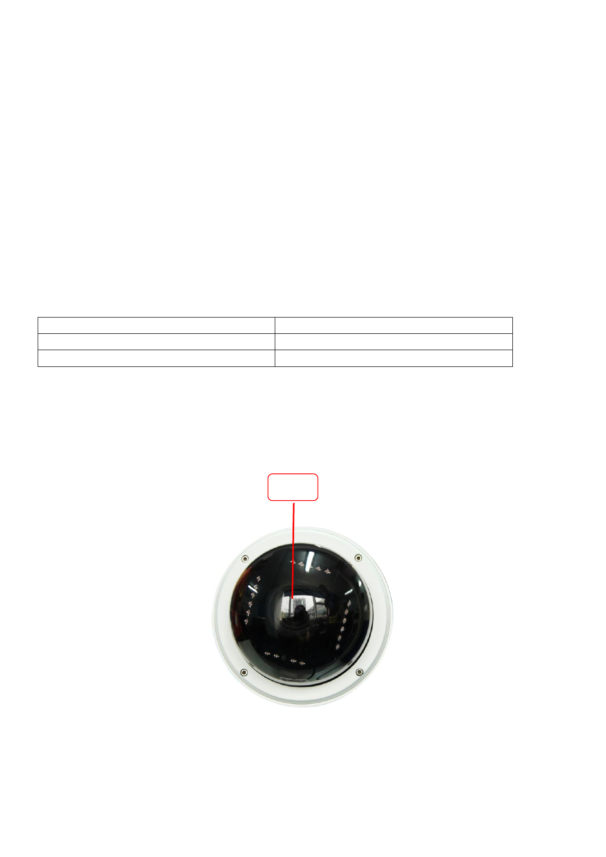
1.4 Physical Description
Front Panel
Lens

5
Figure 1.1
Infrared LED: 21 IR LEDs, night visibility up to 20 meters
LENS: CMOS sensor with zoom lens
Back View
Figure 1.2
WIFI Antenna: Wireless Antenna
Interface View
Infrared Led
Infrared Led
Antenna

6
Figure 1.3
1) I/O alarm terminal block
This network camera provides a I/O alarm terminal block which is used to connect to external input / output
device. The pin(there are four number in the terminal block from no. 1 to no. 4) definitions are descripted
below:
This camera supports I/O alarm, you can go to Settings – Alarm – I/O page to configure it.
2) Audio output interface
The jack is used to plug external speakers.
3) Power Interface
Connect the external power adapter, request for 12V/2A power.
4) Audio input interface
The jack is used to plug external microphone.
1– input
2- input
3- output
4- output

7
5) LAN
10/100M adaptive Ethernet interface. Through this interface, IPCAM can be connected with various network
devices, such as hub, router, etc.
6) Reset button
Press and hold on the reset button for 5 seconds. Releasing the reset button, the password will back to the
factory default administrator password. The default administrator user is admin with no password.
Bottom View
There are up to three labels located on the body of the camera; this is an important feature of original
cameras. If your camera does not have labels, it may be a clone one. Cloned cameras can not use original
firmware and are not eligible for warranty or technical services.
1.5.SD Card Management
The record files of the IPC can be stored in the SD Card.
This camera supports SD Card and the max size of SD card must be under 32G.
You need open the IP Camera, then plug the SD card into SD card slot inside the IP Camera.
When you plug in the SD card during the camera work process, please reboot the camera again, or else the
SD Card may be cannot work well.
Note:
When you re-install the camera, please ensure the tightness with the camera.
2 Access the IP Camera
This chapter explains how to access the camera through browser and RTSP player.
2.1 Access the Camera in LAN
This camera supports HTTP and HTTPS protocols, you can access the camera by two ways.
(1) http:// LAN IP + HTTP Port NO.
Double click the Equipment Search Tool icon and it should find the camera’s IP address automatically after you
plug in the network cable.

8
Figure 2.1
Double click the IP address of the camera; your default browser will open to the camera login page.
(2) https:// LAN IP + HTTPS Port NO.
The default Https port NO. is 443. You can use the url to access the camera: https:// LAN IP + HTTPS port.
Go to Settings - Network - Port panel , you can see and change the https and https port NO.
Figure 2.2
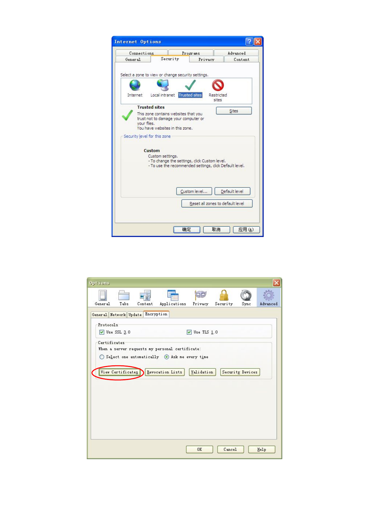
HTTPS(Hypertext Transfer Protocol over Secure Socket Layer) is a safe way to access your camera, the data
transferred on the Internet will be encrypted. Since we can not apply license for every LAN or DDNS URL, the
webpage may pop up a warning like the following picture, you just need to click 'Continue to this website (not
recommended). '
Open Internet Explorer if it is not already opened. Click on Tools, then click Internet Options.
Next, click the Security tab, then click the Trusted sites button.
9
Figure 2.3
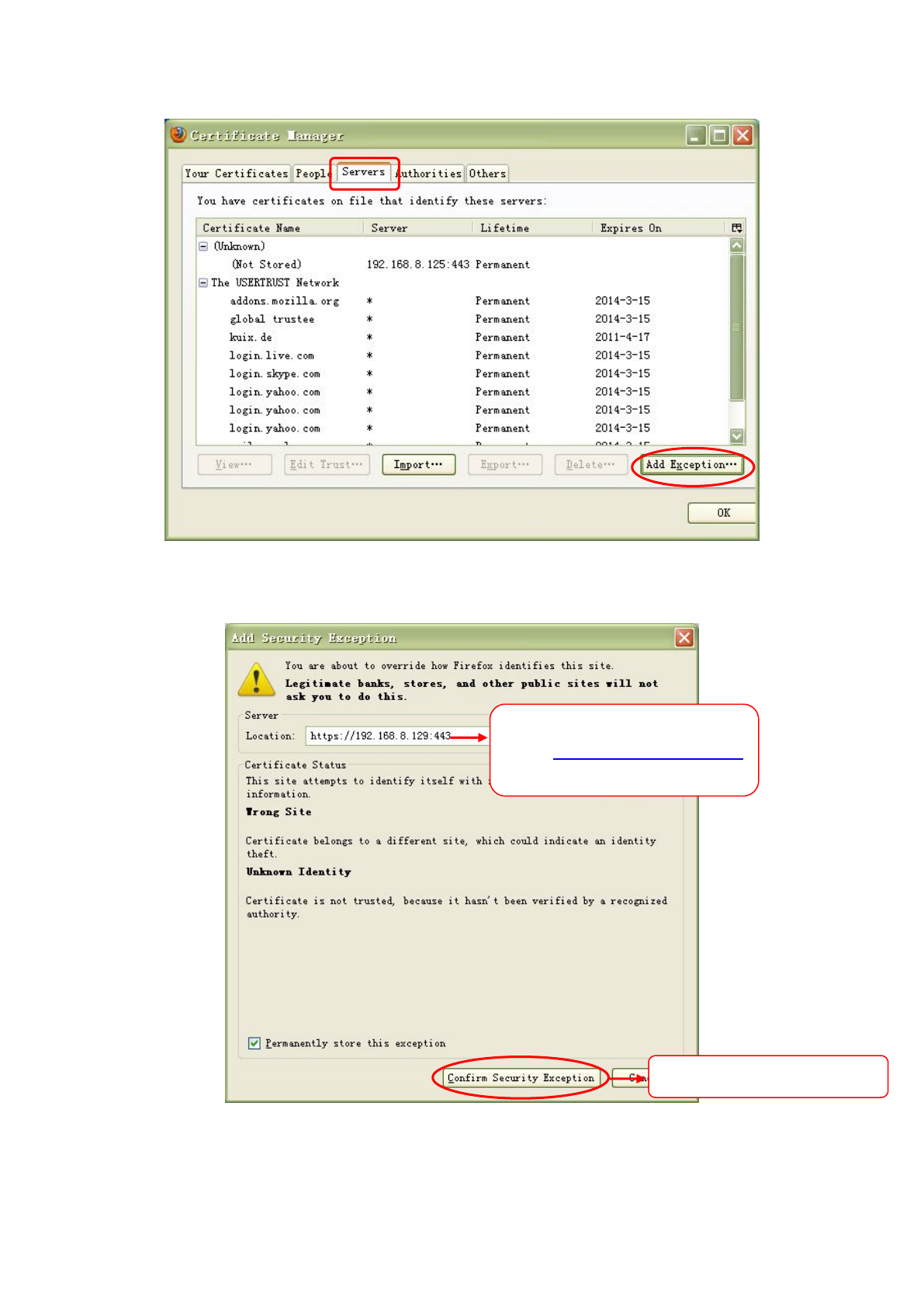
For Firefox, you can add the trusted as the following way:
Tools ---- Options ---- Advanced --- View Certificates --- Servers
Figure 2.4
11
2.2 Access the Camera in WAN
2.2.1 Static IP Addresses
Users who have static IP addresses do not need to set DDNS service settings for remote access. When you
have finished connecting the camera using the LAN IP address and port forwarding, you can access the
camera directly from the Internet using the WAN IP address and port number.
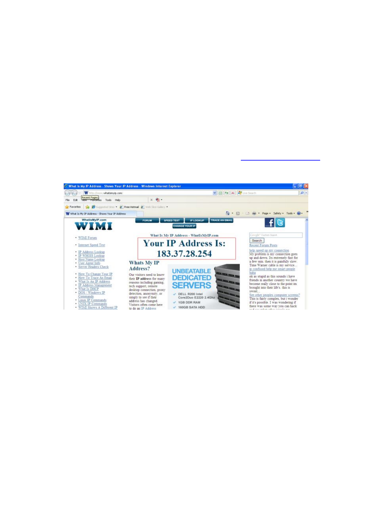
How to Obtain the WAN IP address from a public website
To obtain your WAN IP address, enter the following URL in your browser: http://www.whatismyip.com.The
webpage at this address will show you the current WAN IP.
Figure 2.3
Access your IP Camera from the Internet
You can access the IP Camera from the Internet (remote access). Enter the WAN IP address and port number
in your standard browser. For example, you would enter http:// 183.37.28.254:85
NOTE :
Make sure port forwarding is successful. You can do port forwarding two ways.
1. Login to your router to enable the “UPNP” function. You can then login to the camera as administrator,
choose Network, and then choose UPnP to enable UPnP. Make sure that the status of UPnP reads “UPnP
Successful” on the Device Status page.
2. Do port (HTTP port) forwarding manually. (See Figure 2.11 for further details)
If your router has a Virtual Server, it can do port forwarding. Add the camera’s LAN IP and port which you had
set earlier to your router’s port forwarding settings.
NOTE: If you plug the camera into a router, it will have a dynamic IP address and you need to set DDNS

12
service settings to view it remotely.
2.2.2 Dynamic IP Addresses
DDNS is a service that allows your IP Camera, especially when assigned with a dynamic IP address, to have a
fixed host and domain name. This means that even though your WAN IP address is constantly changing, you
will have a fixed hostname you can use to access your cameras at all times. You can access the camera
directly from the Internet using the hostname and port number.
What is the HTTP Port NO.?
Default HTTP Port is 88
All cameras have the default HTTP port of 88. For example, if the LAN IP link of the camera is
http://192.168.8.102:88, this means that the camera’s HTTP port is 88. You can change port 88 to another port
if you’d like such as 2000 or 8090, which will not be conflict with other existing ports like 25, 21,10000.Here you
can set the port no. between 1 and 65535.
Change the default http NO.88 to another one.
What is Port forwarding?
If you have never done port forwarding before, you can open and view the following link to understand the
basic concept. Port forwarding allows for outside connections to access a specific device on your network from
anywhere in the world. Every router automatically blocks any incoming connections for safety purposes. Using
port forwarding, you are telling your router to allow a connection through a certain port (you can think of it as a
gateway) into your router. You set this port to a specific device, in our case an IP Camera, so it can be
accessed from anywhere in the world.
Click this link to learn more about port forwarding: http://portforward.com/help/portforwarding.htm
How do we configure Port Forwarding?
For this section, we will be using an example:
Let’s say the camera’s LAN IP address is http://192.168.8.100:2000
Step 1: Login to the router, and go to your router’s port forwarding or port triggering menu. Sometimes this is
also under the name of Virtual Server or NAT.
Using the Linksys brand router as an example, we would log into the router, and go to the Applications
& Gaming menu. We would then click on the “Single Port Forwarding” sub-menu.
Step 2: Create a new column using the LAN IP address & HTTP Port of the camera within the router as shown
below, then push OK or Submit to save your settings:

13
Figure 2.7
First method :
Use the embedded DDNS to access the camera via the Internet
Each camera has an embedded unique DDNS domain name, the format of this domain name is
xxxxxx.myipcamera.org. On the bottom of the camera, you can see the domain name sticker with this
information on it.
For example, we can use test09.myipcamera.org. In the camera, click Settings at the top, click “Network” on
the left, then click “DDNS” to get to the DDNS settings page. Here you can see the unique domain name of
your camera.
Figure 2.8
Now you can use “http://Domain name + HTTP Port” to access the camera via the Internet.
Take hostname test09.myipcamera.org and HTTP Port of 2000 for example, the URL link to access the camera
via the Internet would be http:// test09.myipcamera.org:2000.
Second method :
Use the Third party DDNS to access the camera via the Internet
Step 1 Please go to the third party DDNS website(such as www.no-ip.com) to create a free hostname.
Step 2 DO DDNS Service Settings within the Camera
Fill the HTTP Port of the
camera in the columns of
External Port and Internal
Port. Example: 2000
Fill in this section with the
LAN IP of the camera; we
would enter “100” for our
example.
Assign a name for the
port forward setting here

14
Please set DDNS Settings within the camera by hostname, a user name and password you’ve got from
www.no-ip.com
Take hostname ycxgwp.no-ip.info, user name test, password test2012 for example.
Firstly, goes to option of DDNS Settings on the administrator panel.
Secondly, select No-Ip as a server.
Thirdly, fill test as DDNS user, fill password test2012 as DDNS password, fill ycxgwp.no-ip.info as DDNS
domain and server URL, Then click save to make effect. The camera will restart and to take the DDNS settings
effective.
Fourthly, after the restart, login the camera, and go to option of Device Status on the administrator panel, and
check if the DDNS status is successful.
If failed, please double check if you have input the correct hostname, user name, and password, and
try to redo the settings.
NOTE :
If you have set Third Party DDNS successfully ,the Domain Name will be invalid. The Third Party DDNS and
the Domain Name cannot work at the same time, the last time you configured will take effect.
2.3 Using the VLC player
This camera supports RTSP streaming, here you can view the camera using VLC player.
RTSP URL rtsp:// [user name][:password]@IP:HTTP port number/videosream
The part in the square brackets may be omitted.
user name & password:The user name and password to access the camera. This part can be omitted.
IP: WAN or LAN IP address.
Videostream:Here support three mode: videoMain, videoSub and audio. When the network speed is bad, here
you had better select videoSub. If you select audio, you can only hear the sound but cannot see the video.
For example:
IP: 192.168.1.11
HTTP Port number: 88
User name: admin
Password: 123
Here I can enter one of the following URLs in the VLC.
1) rtsp://admin:123@192.168.1.11:88/videoMain
2) rtsp:// @192.168.1.11:88/videoMain
3) rtsp://:123@192.168.1.11:88/videoMain
4) rtsp://admin@192.168.1.11:88/videoMain

15
Open the VLC, and go to MediaOpen Network Stream option, then enter the URL into VLC.
Figure 2.9
Figure 2.10
Sometimes you may need to enter the user name and password again. Click OK and you can see the
real-time preview.

16
Figure 2.11
Figure 2.12
If you cannot play the video in the VLC player, please check the port mapping. You can read Quick Installation
Guide about How to configure port forwarding.
NOTE:
If you modify the camera’s username or password, you had better reboot the camera, or else the
new username and password cannot take effect when you enter the authentication in the VLC.
2.4 IP camera connection to the server
Device supports ONVIF2.2.1 protocol,You can easily access the NVR with ONVIF or server with ONVIF.

17
3 Surveillance Software GUI
Please refer to the Quick Installation Guide if you install the camera at first time. After finishing quick
installation, you can take time to learn the operation of the software.
3.1 Login Window
Figure 3.1
Please check the login window above, it was divided to 5 sections from no. 1 to 4.
Section 1 Enter the User name and password
The default administrator username is admin with a blank password, please reset the password at first using
and prevent unauthorized users login the camera.
Section 2 Stream
The camera supports two stream modes: Main stream and Sub stream. If you want to access the camera form
LAN, here you can select Main stream. If you want to access the camera from Internet, here we recommend
Sub stream.
Note: When the network bandwidth is badly you’d better select Sub Stream and the video will be more
fluency.
Section 3 Select the language
You can select the language you need via click on the language drop-down list to switch.
Section 4 Login the camera
Click Login button and you will see the surveillance windows.(If login the camera for the first time, the page that
2
3
4
1
18
modify the username and password will appears.)
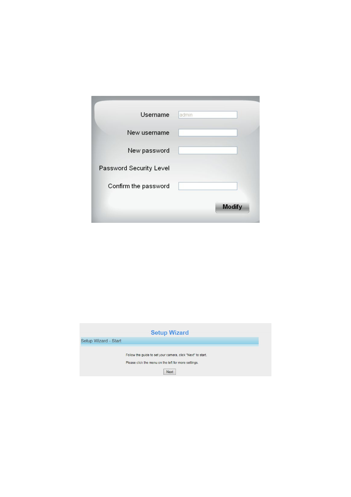
3.2 Modify the Username and Password
When you log in for the first time, it will come to the operating of modify the username and password
automatically.
Figure 3.2
Enter the New Username, New password and Confirm the password.
Click Modify button, you will see the login page again.
3.3 Setup Wizard
After logging in for the first time, you will be directed to the“Setup Wizard”automatically. Here you can set the basic
parameters of camera, such as camera name, camera time, wireless settings, IP configuration.
Figure 3.2
Camera Name: You could give a name for your IP camera.

19
Figure 3.3
System Time: Select the time zone you need to set the date, time,format, etc.
Figure 3.4
Wireless networks: Click Scan, find the SSID of your wireless router, select and enter the password.
Figure 3.5
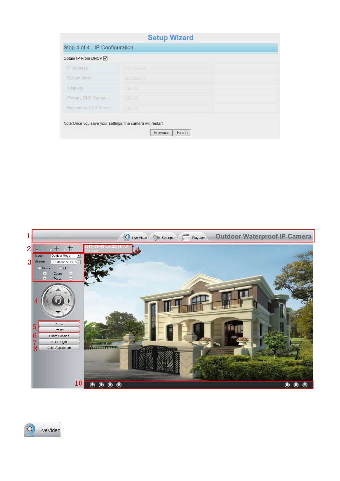
IP: Set the IP address of the camera. You could choose to obtain an IP automatically (DHCP) or set the IP address
manually according to your needs.
20
Figure 3.6
NOTE:
It takes about 1 minute to connect the camera to your router.
3.3 Surveillance Window
Figure 3.3
Section1 Live Video / Settings buttons
: Path to surveillance window. Click this button and back to the surveillance window.

21
: Path to Administrator Control Panel, Click it, and it will lead to Administrator Control Panel and
do advanced settings.
:Click this button and back to the Playback panel to view the record files stored in the SD
Card.
Section2 Multi-Device Window
The firmware inside the camera supports up to maximum of 9 cameras being monitoring at the same time. You
can add other cameras in multi-device setting.
Section3 Mode/ Stream / Mirror/ Flip
Mode
1) 50HZ ---------Indoor surveillance (Region: Europe, China)
2) 60HZ ---------Indoor surveillance (Region: USA, Canada)
3) Outdoor Mode ------ Outdoor surveillance
Stream
The default stream supports multiple modes, For example: HD Mode/720P/30fps/2M meanings: Stream type /
Resolution / Maximum frame rate/ Bit rate. (Different models support different specific mode. )
1) Stream type :It is used to identify the stream type.
2) 720P/ VGA
There are two resolutions, the bigger one is 720P, and the smaller one (VGA) is 640x480 pixels. The bigger the
resolution, the better of the image quality is. If you are accessing the camera via internet and want to get more
fluent video streaming, please select resolution VGA.
3) Maximum frame rate
When the video format is 50Hz, the maximum frame rate is 25 fps. When the video format is 60Hz, the
maximum frame rate is 30 fps. You should lower frame rate when the bandwidth is limited. Normally, when the
frame rate above 15, you can achieve fluently video. The maximum frame rate for each model is different,
please see the “Default Parameters”.
4) Bit rate
Generally speaking, the larger the bit rate is, the clearer video will become. But the bit rate configuration should
combine well with the network bandwidth. When the bandwidth is very narrow, and bit rate is large, that will
lead to video can not play well.
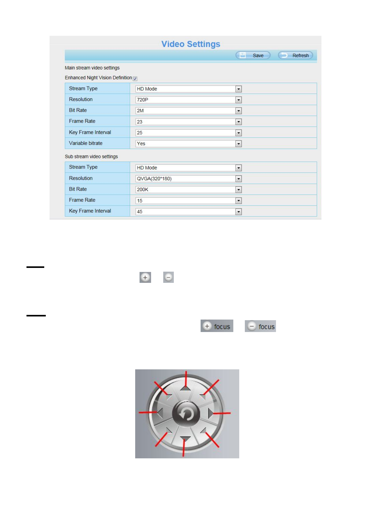
You can reset the stream type on Settings-> Video-> Video Settings panel.
22
Figure 3.5
After changing, please re-login the camera and you can see the modification.
Zoom
Device Support 4x zoom feature, click or ,The focal length of the camera lens will be larger or shrink,
you can adjust the focus distance to the target object size, access to high-definition screen.
Focus
You can manually adjust the focus by clicking on the button or .
Section4 Pan/Tilt Control
1------ Up control button
2------ Down control button
1
2
3
4
5
6
7
8

23
3 ------ Left control button
4------ Right control button
5 ------ Up-Left control button
6------ Up-Right control button
7 ------ Down-Left control button
8------ Down-Right control button
Click this button and go to center
Section5 Cruise / Preset settings
Cruise Settings
The default cruise tracks have two types: Vertical and Horizontal.
Vertical: The camera will rotate from up to down.
Horizontal: The camera will rotate from left to right.
: Start cruise. : Stop cruise.
If you want to define or change the cruise trace, please go to Settings PTZ Preset Settings panel.
How to do cruise?
Firstly: Select one track in the track drop-down list
Secondly: Click Start cruise button, the camera will cruise following the predefined path.
Thirdly: Click stop button and finish cruising.
Preset settings
Select one of these

24
IPCAM supports 16 preset positions, which is considered enough for DIY home & small business surveillance
market.
The default preset position is TopMost, BottomMost, LeftMost, RightMost, you can add other preset positions.
Add Click this icon to save the position you need the camera to remember
Delete Select one preset position and click this button to delete it.
GO Select one preset position in the preset drop-down list and click Go to make the camera move the
preset position
How to do preset position?
Firstly, move the camera and stop at a desired place where you want make preset position.
Secondly, click button and enter a descriptive name for the preset position. The preset position cannot
contain special characters. Then click OK to save it. If you want to reset the preset position, click Cancel.
After that, you can move the camera and stop at another place, and set another preset position. You can do all
the 16 preset positions with this method.
If you want to see one preset position you have set, only select the preset position name from the preset
drop-down list, and click go button, the camera will go to the preset position.
Section 6 Guard Position
After setting the guard position, your camcorder will automatically return to the guard position within a
predetermined time (manually setting) when it stopsmoving (manually or cruise). You could refer to the
following method in chapter 4.7.4 ( Guard Position Settings).
Section7 IR LED Lights
Click Infra led and there are three modes to adjust the infrared led: Auto, Manual and Schedule.

25
Auto: Select it and the camera will adjust the infra led (on or off) automatically.
Manual: Select it and you can turn on or turn off the infra led manually.
Schedule: Select it and the IR led light will be off at the schedule period. If you want to define or change the IR
led lights schedule time, please go to Settings---> Video--->IR LED Schedule page.
Section8 Image quality settings
In this page, you can tune Hue, Brightness, Contrast, Saturation, and Sharpness to get higher quality.
Section9 OSD
If you have added time and camera name in the video, you can see it in the live window.
Go to Settings ---Basic settings---Camera name panel, and you can change another device name. The
default device name is anonymous.
Go to Settings ---Basic settings---Camera time panel and adjust the device time.
Go to Settings ---Video---On Screen Display panel, you can add or no add OSD.
Section10 Play/Stop/ Talk/Audio/ Snap/ Record/ Full screen button
1------Play Click it to play the video of the camera
2------Stop Click it to stop the video of the camera
3------ Talk Click the button and the icon will become to , then talk to the microphone that connected
with PC, people around the camera can here your voice. Click the icon again and stop talking.
4------ Audio Click this icon, the icon will become to you can hear the sound around the camera by the
earphone or speakers that connected with PC.
5----- Snapshot Click it to make snapshot and it pop-up a window which picture you snapshot, right click in
the window and save the picture to anywhere you want.
1
2
3
5
6
7
4

26
6----- Record Click the icon and the camera start recording, you can see a green dot in the live window.
Click again and stop recording. The default storage path is C:\IPCamRecord. You can change the storage path:
Go to Settings- >Record->Storage Location panel.
7------Full Screen Click it to make full-screen, or you can double click the surveillance screen to make
full-screen. Double click again and exit full-screen.
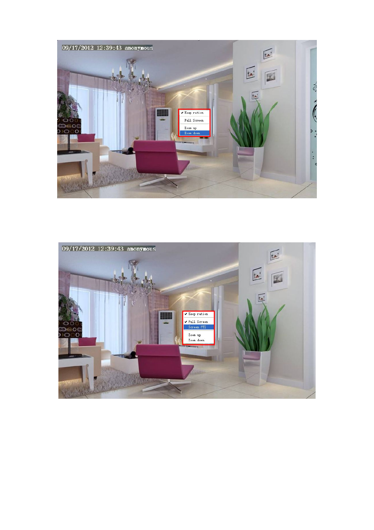
Onscreen Mouse Control
Right click the mouse and you can adjust the screen ration, full screen and Zoom up.
Figure 3.6
Keep ration: Select it and the camera will adjust the size of live window based on the the computer monitor
automatically. Sometimes there is a black border around the video, please select Keep ration to get a better
visual quality .
Full Screen: Select it and Click it to make full-screen, press ESC and exit full-screen.
Zoom up:
First Method: Here is a convenient and fast solution to Zoom up/down screen by Clicking Video Screen and
adjusting Mouse pulley, or by press the CTRL key and click the mouse left button.
Second Method: Click it and the live view will be digital zoomed up, then click Zoom Down and the live view
back to original size.
27
Figure 3.7
When you select the Full Screen, then click right mouse, there is a Screen PTZ button.
Figure 3.8
Click the Screen PTZ button and put the mouse on the screen to indicate the camera move direction you
prefer, press the left mouse, the camera will move to the corresponding direction. Loosen the mouse and stop
moving. Press Esc button or double click right mouse and cancel the function.
NOTE: For Mac OS, the plugin cannot support Onscreen Mouse Control, so you cannot allow to use it.

28
4 Advanced Camera Settings
Click the button “Settings”, goes to Administrator Control Panel to make advanced camera settings.
4.1 Status
Status contains four columns: Device Information, Device Status, Session Status and Log, it will show you
various information about your camera.
4.1.1 Device Information
Figure 4.1
Camera Model: The model of the device.
Camera Name: The Device Name is a unique name that you can give to your device to help you identify it.
Click Basic Settings and go to Camera name panel where you can change your camera name. The default
device name is anonymous.
Camera ID: Display the wired MAC address of your camera. For example Device ID is HJYFC8613P03, the
same MAC ID sticker is found at the bottom of the camera.
Camera Time: The system time of the device. Click Basic Settings and go to Camera time panel and adjust
the time.
System Firmware Version: Display the System Firmware version of your camera.
Application Firmware Version: Display the application firmware version of your camera.
Plug-in Version: Display the plug-in version of your camera
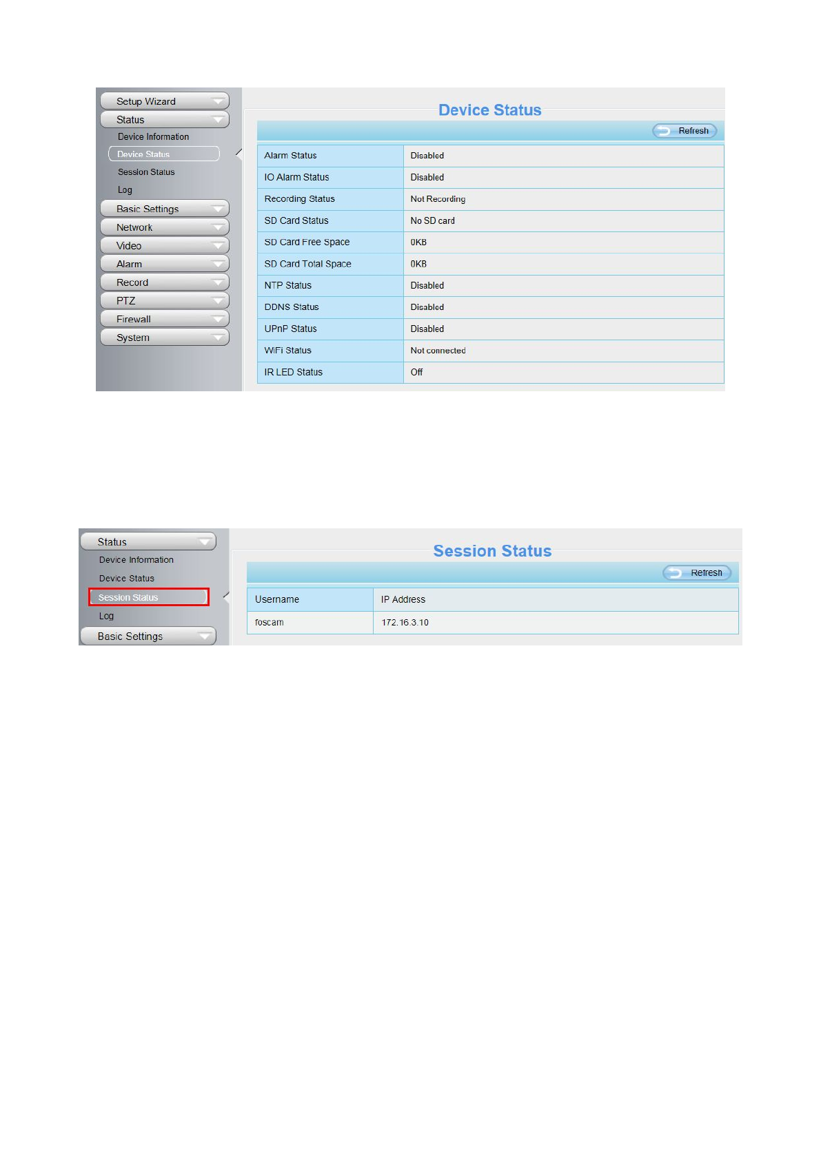
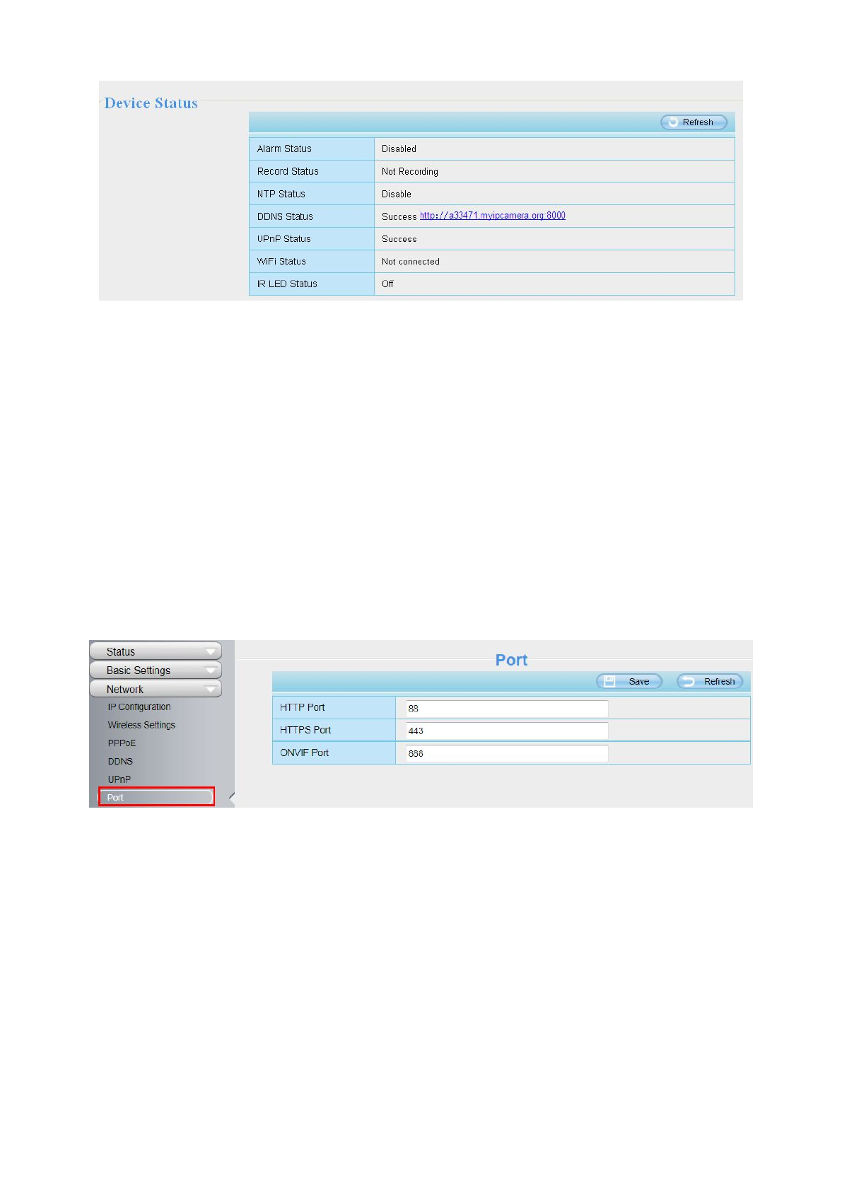
4.1.2 Device Status
On this page you can see device status such as Alarm status/ Record Status ,DDNS status ,WIFI status and so
on.
29
Figure 4.2
4.1.3 Session Status
Session status will display who and which IP is visiting the camera now.
Figure 4.3
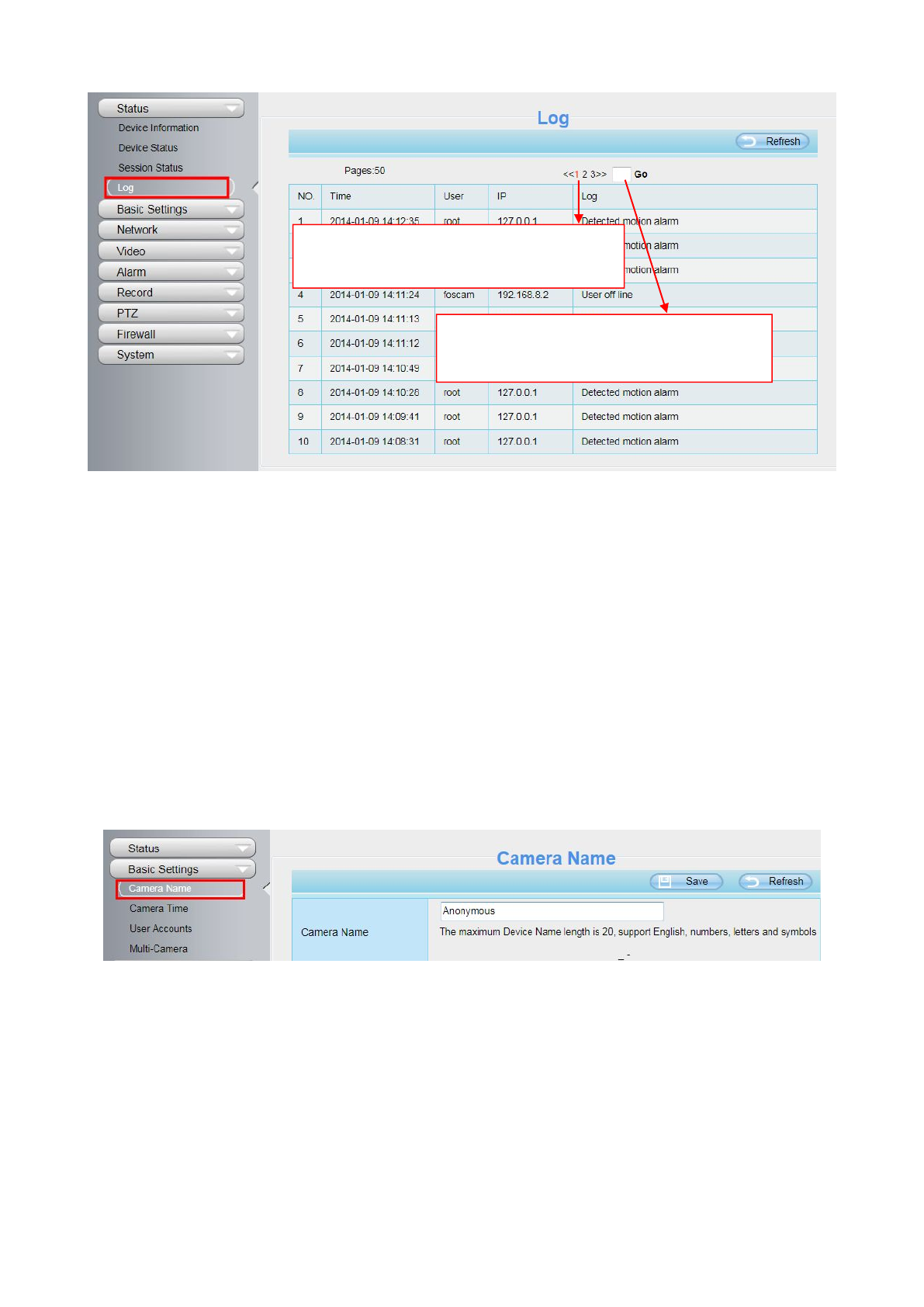
4.1.4 Log
The log record shows who and which IP address accessed or logout the camera and when.
30
Figure 4.4
Reboot the camera and clear the log records.
4.2 Basic Settings
This section allows you to configure your camera’s Name, Time, User account and Multi-Camera.
4.2.1 Camera Name
Default alias is anonymous. You can define a name for your camera here such as apple. Click Save to save
your changes. The alias name cannot contain special characters.
Figure 4.5
4.2.2 Camera Time
This section allows you to configure the settings of the internal system clocks for your camera.
Click the page number and go to the
corresponding page to see more logs.
Fill in one page number, click Go button
and go to the corresponding page.

31
Figure 4.6
Time Zone: Select the time zone for your region from the drop-down menu.
Sync with NTP server: Network Time Protocol will synchronize your camera with an Internet time server.
Choose the one that is closest to your camera.
Sync with PC: Select this option to synchronize the date and time of the Network Camera with your computer.
Manually: The administrator can enter the date and time manually. Please select the date and time format.
use DST: Select the use DST, then select the daylight saving time from the drop-down menu.
Click Save button to submit your settings.
4.2.3 User Accounts
Here you can create users and set privilege, visitor, operator or administrator. The default user account is
admin, with a blank password. You can enter the users accounts of visitor 、operator and adminstrator
Manually.
Figure 4.7

32
How to change the password of administrator?
Firstly, select the account of administrator, then select “Change password”, enter the old password and the
new password, lastly click modify to take effect.
Figure 4.8
How to add account ?
Select one blank column, then enter the new user name, password and privilege, last click Add to take effect.
You can see the new added account on the Account list.
Figure 4.9

33
Figure 4.10
Delete:Select the account which you want to delete, then click Delete button to take effect.
Note: The default admin account cannot be deleted, but you can add other administrator users.
How to change the username ?
Firstly, select the account which you want to change the username, then select “Change username”, enter the
new password, lastly click modify to take effect.
Figure 4.11
4.2.4 Multi-Camera
If you want to view multi-surveillance screens on one window, you need to login one camera, and set it as the
main device, and do Multi-Device Settings, add other cameras to the first one camera. Before you do

34
multi-cams settings, you need to assign different port such as 81, 82, 83, 84, 85, 86, 87, 88 to the cameras if
there is 8 cams installed.
The firmware within the camera can support a maximum of 9 devices monitoring all at the same time. This
page you can both add MJPEG and H.264 series cameras to the first camera and view multi-surveillance
screen on one window.
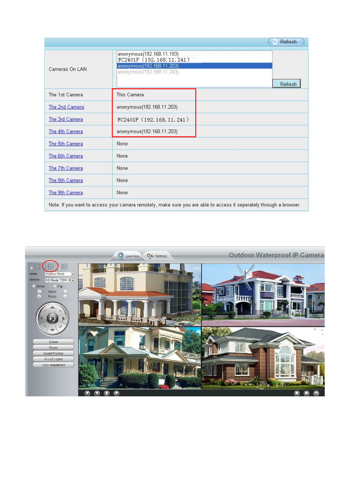
Add cameras in LAN
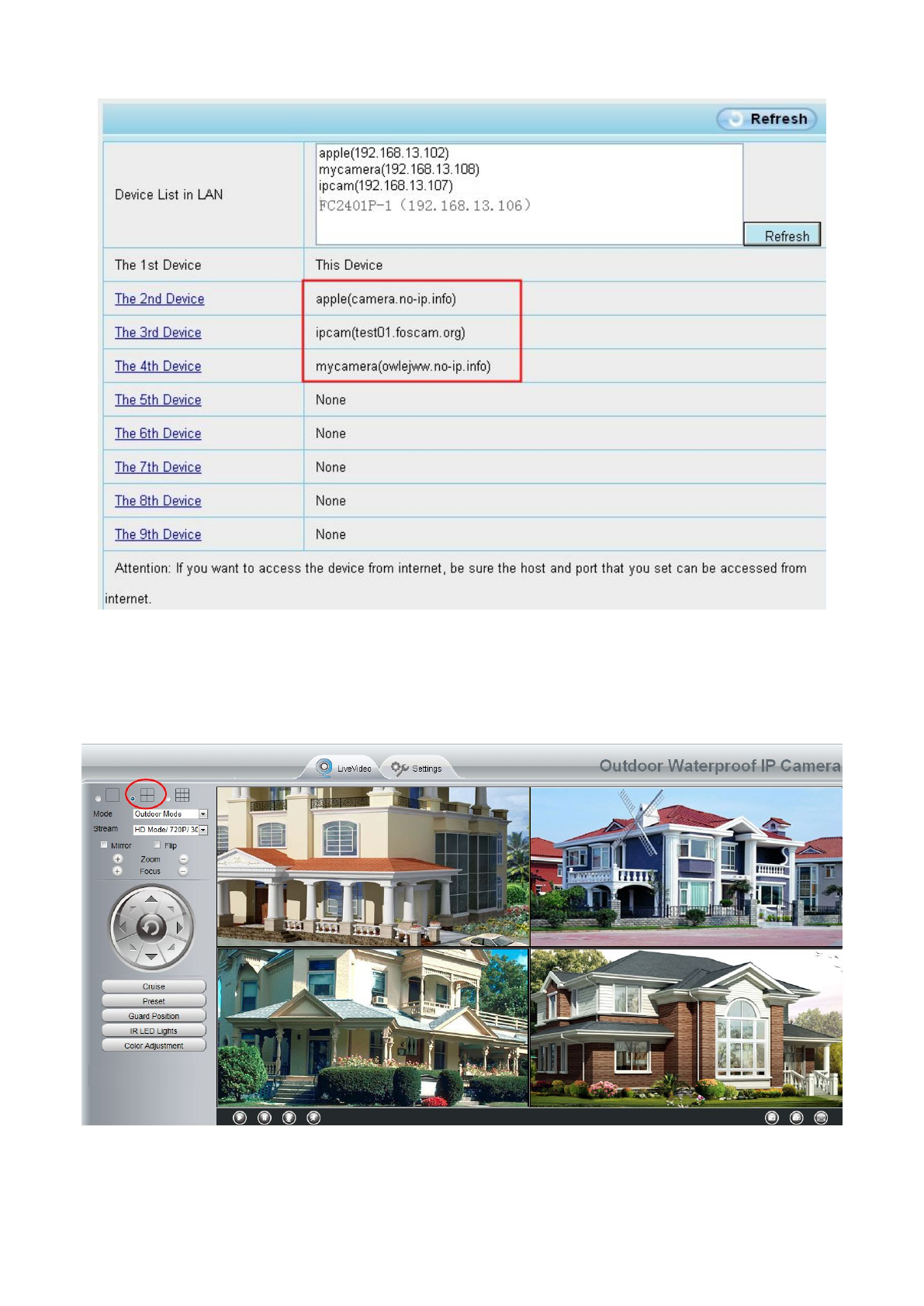
In Multi-Device Settings page, you can see all devices searched in LAN. The 1st Device is the default one. You
can add more cameras in the list in LAN for monitoring. The camera’s software supports up to 9 IP Cameras
online simultaneously. Click The 2nd Device and click the item in the Device List in LAN, the Alias, Host and
Http Port will be filled in the boxes below automatically. Enter the correct username and password then click
Add. Add more cameras in the same way.
Figure 4.12
Camera Model: Our Company produces two series cameras: MJPEG and H.264. Here will show you which
series the camera belongs to.
35
Figure 4.13
Back to Surveillance Windows, and click Four Windows option, you will see four cameras you added.
Figure 4.14
36
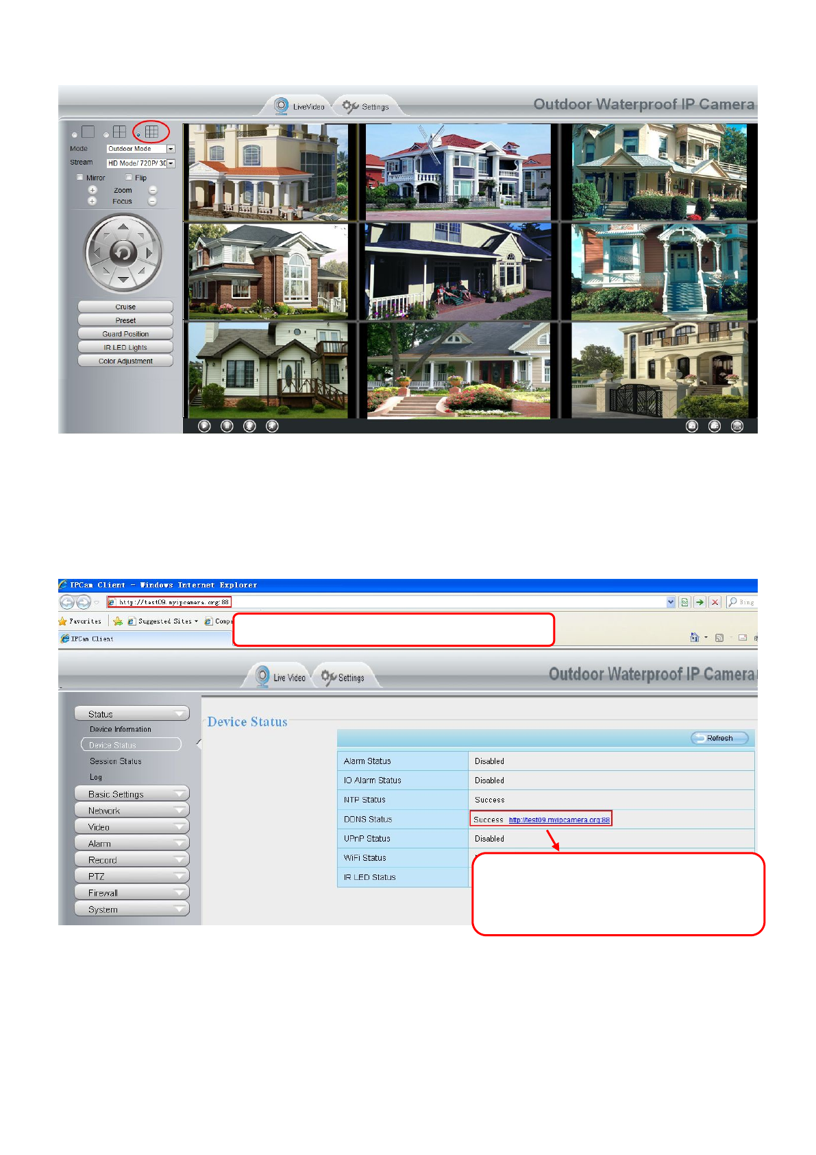
Figure 4.15
Add cameras in WAN
If you want to view all cameras via the internet(remote computer), you will need to add them using DDNS
domain name. Firstly, make sure all of the cameras you added can be accessed through the internet.
Login to the first camera using a DDNS domain name and port.
Figure 4.16
Click Multi-Device Settings. Choose The 2nd Device. Fill in the 2nd camera’s name, DDNS domain name,
port number. Enter user name and password and then choose Add.
Use DDNS domain name and port to login
Make sure each camera you need add
could login with DDNS name and port
NO.

37
Figure 4.17
1 ---- The camera model: MJ or H264.
2 ---- The 2nd camera’s name
3 ---- Fill in the 2nd camera’s DDNS host not LAN IP
4 ---- Enter the 2nd camera’s user name and password
5 ---- Click Add button and to take effect
NOTE: Here the Host must be entered as the second camera’s DDNS domain name, not its LAN IP.
38
Figure 4.18
Return to video window. You will see all of the cameras accessible through the internet.
When you are away from home, you can use the first camera’s DDNS domain name and port to view all the
cameras via internet.
Figure 4.19

39
4.3 Network
This section will allow you to configure your camera’s IP, PPPoE, DDNS, Wireless Settings, UPnP and Port.
4.3.1 IP Configuration
If you want to set a static IP for the camera, please go to IP Configuration page. Keep the camera in the same
subnet of your router or computer.
Figure 4.20
Changing settings here is the same as using the Equipment Search Tool.
It is recommended that you use the subnet mask, gateway and DNS server from your locally attached PC. If
you don’t know the subnet mask, gateway and DNS server, you can check your computer’s local area
connection as follows:
Control Panel Network Connections Local Area Connections Choose Support Details.

40
Figure 4.21
Figure 4.22
If you don’t know the DNS server, you can use the same settings as the Default Gateway.
41
4.3.2 Wireless Settings
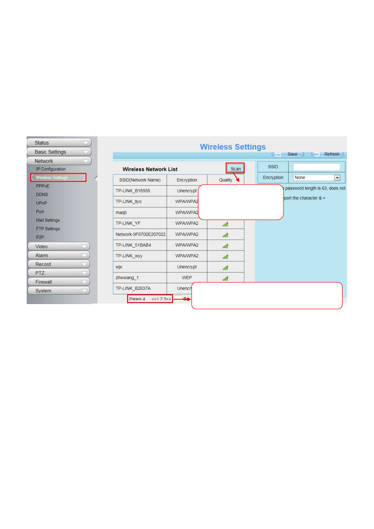
Step 1: Choose “Settings” on the top of the camera interface, and go to the “Network” panel on the left side of
the screen, then click “Wireless Settings.”
Click the Scan button and the camera will detect all wireless networks around the area. It should also display
your router in the list (Figure 4.23).
Figure 4.23
Step 2: Click the SSID (name of your router) in the list, the corresponding information related to your network,
such as the name and the encryption, will be filled into the relevant fields automatically.
You will only need to fill in the password of your network. Make sure that the SSID, Encryption and the
password you filled in are exactly the same for your router.
Click the Page number to see other wireless
networks devices if there are more than 10.
Click the Scan button
to search for wireless
networks.

42
Figure 4.24
Step 3: Please click on the Save button after all settings have been entered and disconnect the network cable.
Never shut down the power of the camera until the IP camera is able to connect to the wireless network.
The LAN IP address will disappear on the window of Equipment Search Tool when the camera is configuring a
wireless connection. Wait about 1 minute, the camera should obtain a wireless connection, and the LAN IP of
the camera will show again on the window of the Equipment Search Tool. The IP address may have changed
after the camera receives a wireless connection; we recommend setting a static local IP address if this IP
address changes by right clicking the camera in Equipment Search Tools, setting a static IP, and pushing OK
(see Figure4.36).
Congratulations! You have set up the wireless connection of the camera successfully.
NOTE:
If you fail to make a wireless connection, please refer to your seller or contact us directly for
assistance.
4.3.3 PPPoE
If you are using a PPPoE connection, enable it and enter the User Name and Password for your PPPoE
account.

43
Figure 4.25
4.3.4 DDNS
The camera has embedded a unique DDNS domain name when producing, and you can directly use the
domain name, you can also use the third party domain name.
IPCAM domain name
Here take test09.myipcamera.org for example. Go to option of DDNS on the Settings->Network panel, you
can see the domain name.
Figure 4.26
Now you can use http:// Domain name + HTTP Port to access the camera via internet.
Take hostname test09.myipcamera.org and HTTP Port no. 800 for example, the accessing link of the camera
via internet would be http:// test09.myipcamera.org:800
Restore DDNS to factory: If you have configured Third Party DDNS successfully, but you want to use
Manufacturer’s DDNS again , here click this button and start Manufacturer’s DDNS Service.
Third Party Domain Name Settings
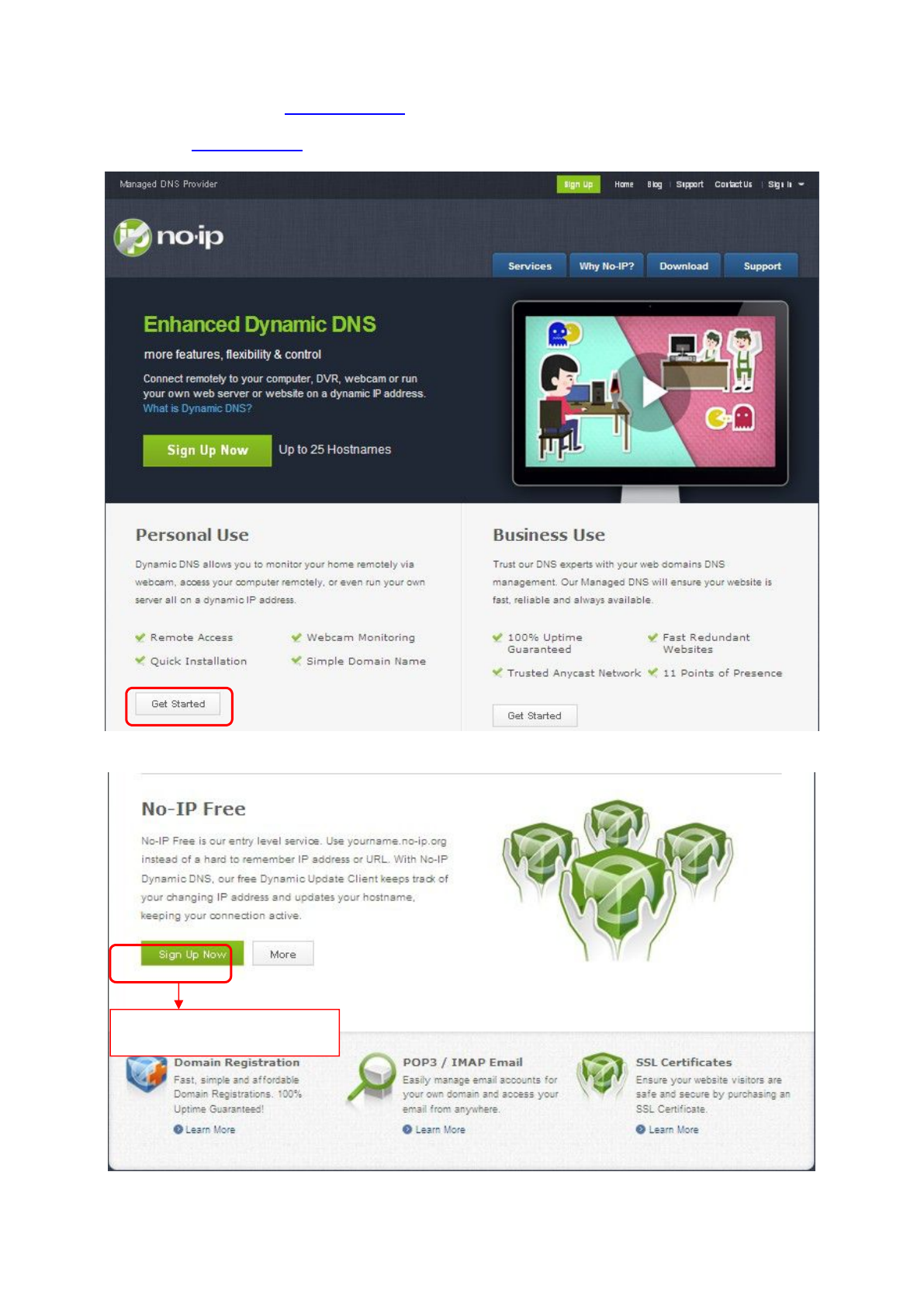
User can also use third part DDNS, such as www.no-ip.com. ,www. 3322.com
Here take www.no-ip.com for example:

45
Please register an account step by step according to instructions on www.no-ip.com
After registration, please login your email which used to register. You will receive an email from website, please
click the link to activate your ACCOUNT as indicated in email.
Secondly: Login the link with the registered username and password to create your domain name.
Figure 4.29
Figure 4.30
Please create the domain name step by step according to instructions on www.no-ip.com

46
Step 2, DO DDNS Service Settings within the Camera
Please set DDNS Settings within the camera by hostname, a user name and password you’ve got from
www.no-ip.com
Take hostname ycxgwp.no-ip.info, user name test, password test2012 for example.
Firstly, goes to option of DDNS Settings on the administrator panel.
Secondly, select No-Ip as a server..
Thirdly, fill test as DDNS user, fill password test2012 as DDNS password, fill ycxgwp.no-ip.info as DDNS
domain and server URL, Then click save to make effect. The camera will restart and to take the DDNS settings
effective.
Fourthly, after the restart, login the camera, and go to option of Device Status on the administrator panel, and
check if the DDNS status is successful.
If failed, please double check if you have input the correct hostname, user name, and password, and
try to redo the settings.
NOTE:
If you have set Third Party DDNS successfully ,the Domain Name will be invalid. The Third Party DDNS and
the Domain Name cannot work at the same time, the last time you configured will take effect.
②Do port forwarding within the router
Example: The camera’s LAN IP address is http://192.168.8.100:2000 , Media port no. is 9200.
Firstly, login the router, goes to the menu of Port Forwarding or Port Trigger (or named Virtue
Server on some brands of router). Take Linksys brand router as an example, Login the router, and goes
to Applications & Gaming->Single Port Forwarding.
Secondly, Create a new column by LAN IP address & HTTP Port No. of the camera within the router showed
as below.

47
Figure 4.31
③Use domain name to access the camera via internet
After the port forwarding is finished, you can use the domain name+ http no. to access the camera via
internet. Take hostname ycxgwp.no-ip.info and http no. 2000 for example, the accessing link of the camera
via internet would be http:// ycxgwp.no-ip.info:2000
4.3.5 UPnP
Figure 4.32
The default UPnP status is closed. You can enable UPnP, then the camera’s software will be configured for
port forwarding. Back to the “Device Status” panel, you can see the UPnP status:
Assign a name
as you like here
Fill the Media Port no. of the
camera on the column of
External Port and Internal Port
48
Figure 4.33
The camera’s software will be configured for port forwarding. There may be issues with your routers security
settings, and sometimes may error. We recommend you configure port forwarding manually on your router.
4.3.6 Port
This camera supports HTTP Port. HTTP Port is used to access the camera remotely. If you want to access the
camera and view the video, the HTTP Port must both be configured correctly.
HTTP port: By default, the HTTP port is set to 88. Also, they can be assigned with another port number
between 1 and 65535. But make sure they can not be conflict with other existing ports like 25, 21.
Figure 4.34
Another way to change the HTTP port NO.
Step 1: Open the Equipment Search Tool, select the camera you would like to change the port of, right click on
the IP address, and click on ”Network Configuration”, this brings up the network configuration box as shown in
Figure 4.35 and 4.36.

49
Figure 4.35
Figure 4.36
Step 2: Enter the username and password of the Administrator (default username is admin with a blank
password), and click “OK” to apply changes.
Step 3: Wait around 10 seconds, you’ll see that the camera’s LAN IP address has changed. In our example it
was changed to 2000, so we see http://192.168.8.102:2000 in Equipment Search Tool. Also, the LAN IP
address is now fixed at a static IP address of http://192.168.8.102:2000. This IP address will not change even if
the camera is powered off and back on, the camera will remain on this LAN IP address. This is very important
that a static LAN IP address is set, or you may have problems later with remote access and seeing the camera
remotely if the camera loses power and reconnects on a different LAN IP address. Make sure you set a static
LAN IP address!
Select which camera
you’d like to change the
port for, and right click
Modify the Http Port.
Enter the Username and
password, click OK.

50
Figure 4.37
Note: If the camera cannot be accessed, please make sure the port forwarding is succeed.
HTTPS port: The default port is 443. You can use the url to access the camera: https:// IP + HTTPS port NO.
ONVIF port: By default, the ONVIF port is set to 888. Also, they can be assigned with another port number
between 1 and 65535(except 0 and 65534). But make sure they can not be conflict with other existing ports.
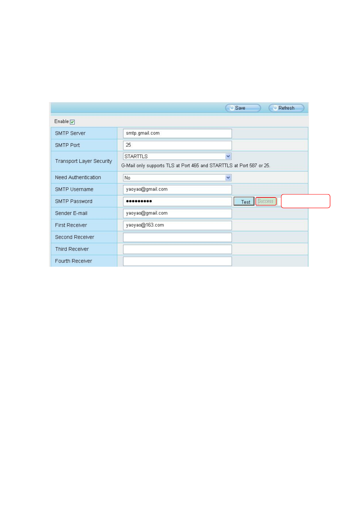
4.3.7 Mail Settings
If you want the camera to send emails when motion has been detected, here Mail will need to be configured.
Figure 4.38
1-----SMTP Server/ Port /Transport Layer Security Enter SMTP server for sender. SMTP port is usually set
as 25. Some SMTP servers have their own port, such as 587 or 465, and Transport Layer Security usually is
None. If you use Gmail, Transport Layer Security must be set to TLS or STARTTLS and SMTP Port must be
set to 465 or 25 or 587, which port you choose should be decided by which Transport Layer Security you
select.
51
2-----SMTP Username/ password ID account and password of the sender email address
3-----Sender E-mail Mailbox for sender must support SMTP
4-----Receiver Mailbox for receiver need not support SMTP,you can set 4 receivers
5-----Save Click Save to take effect
6-----Test Click Test to see if Mail has been successfully configured.
Click Test to see if Mail has been successfully configured.
Figure 4.39
If the test success, you can see the Success behind the Test, at the same time the receivers will receive a test
mail.
If the test fails with one of the following errors after clicking Test, verify that the information you entered is
correct and again select Test.
1) Cannot connect to the server
2) Network Error. Please try later
3) Server Error
4) Incorrect user or password
5) The sender is denied by the server. Maybe the server need to authenticate the user, please check it and try
again
6) The receiver is denied by the server. Maybe because of the anti-spam privacy of the server
7) The message is denied by the server. Maybe because of the anti-spam privacy of the server
8) The server does not support the authentication mode used by the device
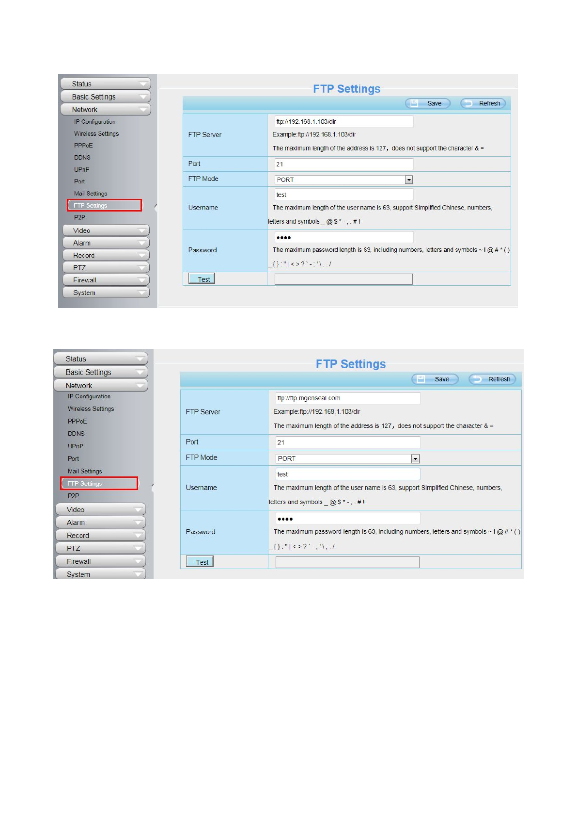
4.3.8 FTP Settings
If you want to upload record files and images to your FTP server,you can set FTP Settings.
Test result
52
Figure 4.40
Figure 4.41
FTP server: If your FTP server is located on the LAN, you can set as Figure4.43.
If you have an FTP server which you can access on the internet, you can set as Figure 4.44
Port: Default is port 21. If changed, external FTP client program must change the server connection port
accordingly.
FTP Mode: Here supports two modes: PORT and PASV.
Username/password: The FTP account and password.
Click Save to take effect.
Click Test to see if FTP has been successfully configured.
53
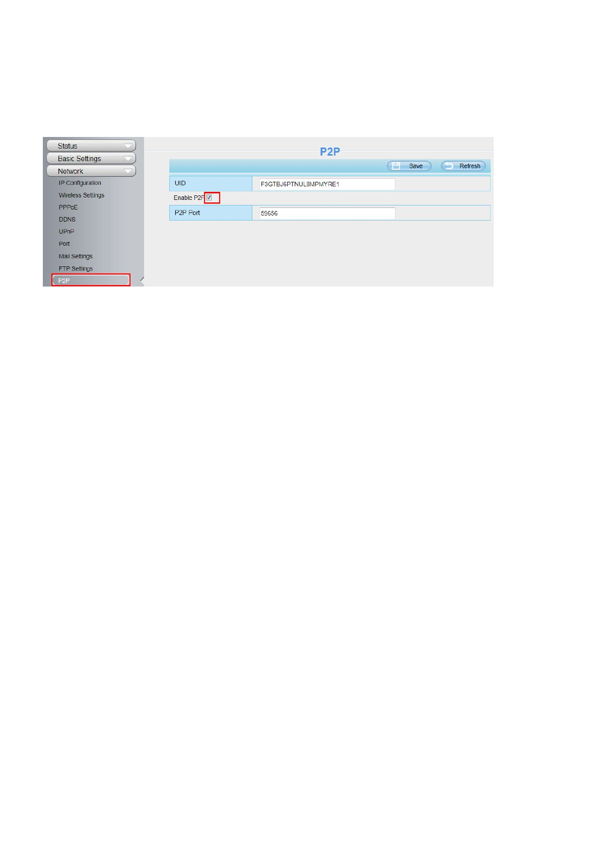
4.3.9 P2P
Access the IP Camera by Smart Phone (Android or iOS operating system)
First of all, you need to open the P2P function of the IP Camera at “Settings-->Network-->P2P”.
Figure 4.1
4.4 Video
This section allows you to configure Video stream settings, On screen display and Snapshot settings.
4.4.1 Video Settings
There are two ways to set the stream video settings. They are main stream video settings and sub stream
video settings.

54
Figure 4.42
Enhanced Night video Definition: The camera will automatically drop the frame to extend the recording time
in the night.
Stream type: There are four types to identify different streams you have set. If select the HD Mode, the clearer
video will become, and it will take up more bandwidth; If select the Smooth Mode, the bandwidth is very narrow,
and bit rate is large, that will lead to video can not play well. The Equilibrium Model is a value between HD
Mode and Smooth Mode.
Resolution: The camera supports multiple types, For example: 960P, 720P, VGA, QVGA. The higher the
resolution is, the clearer video will become. But the code flux will become larger too, and it will take up more
bandwidth.
Bit rate: Generally speaking, the larger the bit rate is, the clearer video will become. But the bit rate
configuration should combine well with the network bandwidth. When the bandwidth is very narrow, and bit rate
is large, that will lead to video can not play well.
Frame rate: Note that a larger frame size takes up more bandwidth. When the video format is 50Hz, the
maximum frame rate is 25 fps. When the video format is 60Hz, the maximum frame rate is 30 fps. You should
lower frame rate when the bandwidth is limited. Normally, when the frame rate above 15, you can achieve
fluently video. The maximum frame rate for each model is different, please see the “Default Parameters”.
Key Frame Interval: The time between last key frame and next key frame. The shorter the duration, the more
likely you will get a better video quality, but at the cost of higher network bandwidth consumption.

55
Variable bitrate: Select the Bit rate type to constant or variable. If select Yes, the camera will change the video
bit rate according to the situation, but will not more than the maximum parameter "Bit Rate"; If select No, the Bit
Rate is unchanged.
4.4.2 On Screen Display
This page is used to add time-stamp and device name on the video.
Figure 4.43
Display Timestamp: There are two options: Yes or NO. Select Yes and you can see the system date on the
video.
Display Camera Name: There are two options: Yes or NO. Select Yes and you can see the device name on
the video.
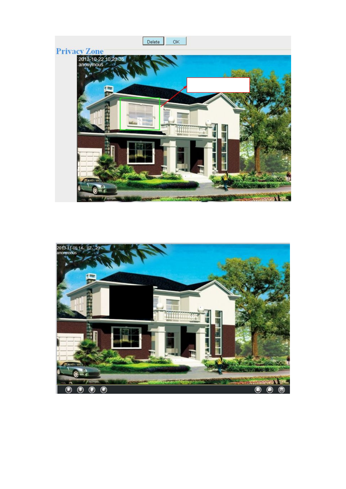
4.4.3 Privacy Zone
This page is used to set some mask as privacy zone on the video.
Figure 4.44
Allow On Screen Display Mask: There are two options: Yes or NO. Select yes and draw a mask area on the
video, the mask area will be black on the video.
56
Figure 4.45
Click Back button and return to the OSD page, click Save to take effect.
Back to the surveillance window, you can see the mask area as the following picture:
Figure 4.46
4.4.4 Snapshot Settings
On this page you can set the snapshot pictures’ image quality and the storage path.
The mask area

57
Figure 4.47
Snap Quality: Low, Middle and High. The higher the quality, the picture will be clearer.
Pictures Save To: FTP or SD Card. If you have done FTP and Alarm settings, when alarming, the camera will
snap pictures to the FTP automatically. If select SD Card as the save path, make sure the camera has inserted
in the SD card.
Enable timing to capture
To enable capture interval, follow the steps below:
1 Select Enable timing to capture
2 Capture interval:The interval time between two captures.
3 Select the capture time
Capture anytime
Click the black button up the MON, you will see all time range turn red. When something moving in the
detection area at anytime, the camera will capture.
Specify an capture schedule
Click the week day words, the corresponding column will be selected. For example, click TUE, the all
column of TUE turns to red, that means during Tuesday whole day, the camera will capture.
Press the left mouse and drag it on the time boxes, you can select the serial area,
4 Click Save button to take effect.
Especificaciones del producto
| Marca: | SAB |
| Categoría: | cámara de seguridad |
| Modelo: | IP1400 |
¿Necesitas ayuda?
Si necesitas ayuda con SAB IP1400 haz una pregunta a continuación y otros usuarios te responderán
cámara de seguridad SAB Manuales

3 Septiembre 2024
3 Septiembre 2024
3 Septiembre 2024
29 Agosto 2024
28 Agosto 2024
28 Agosto 2024
cámara de seguridad Manuales
- cámara de seguridad Honeywell
- cámara de seguridad Motorola
- cámara de seguridad Topcom
- cámara de seguridad Canon
- cámara de seguridad Abus
- cámara de seguridad Acti
- cámara de seguridad Apeman
- cámara de seguridad Hikvision
- cámara de seguridad Nedis
- cámara de seguridad Gembird
- cámara de seguridad Yale
- cámara de seguridad Eminent
- cámara de seguridad Swan
- cámara de seguridad Overmax
- cámara de seguridad TP Link
- cámara de seguridad Trust
- cámara de seguridad Elro
- cámara de seguridad Axis
- cámara de seguridad Hama
- cámara de seguridad Maginon
- cámara de seguridad Smartwares
- cámara de seguridad Profile
- cámara de seguridad Fenton
- cámara de seguridad Eufy
- cámara de seguridad Somfy
- cámara de seguridad Netgear
- cámara de seguridad Ubiquiti
- cámara de seguridad First Alert
- cámara de seguridad Dahua
- cámara de seguridad Foscam
- cámara de seguridad Targa
- cámara de seguridad D-Link
- cámara de seguridad Lorex
- cámara de seguridad Humax
- cámara de seguridad Iget
- cámara de seguridad Vivotek
- cámara de seguridad Storage Options
- cámara de seguridad Swisstone
- cámara de seguridad Sinji
- cámara de seguridad Ferguson
- cámara de seguridad Sricam
- cámara de seguridad Kompernass
- cámara de seguridad Speco Technologies
- cámara de seguridad ZKTeco
- cámara de seguridad Brinno
- cámara de seguridad Tenvis
- cámara de seguridad Nordval
- cámara de seguridad V-Tac
- cámara de seguridad Jablocom
- cámara de seguridad Beseye
- cámara de seguridad Pelco
- cámara de seguridad Exacq
- cámara de seguridad Brickcom
- cámara de seguridad Home Protector
- cámara de seguridad Escam
- cámara de seguridad Mr Safe
- cámara de seguridad Duramaxx
- cámara de seguridad EasyN
Últimos cámara de seguridad Manuales
19 Octubre 2024
18 Octubre 2024
5 Octubre 2024
Fenton 351.183 - CCTV Security 4 Cam Wireless NVR kit Manual de Usario
22 Septiembre 2024
8 Septiembre 2024
8 Septiembre 2024
8 Septiembre 2024
8 Septiembre 2024
8 Septiembre 2024
8 Septiembre 2024